Table of Contents
Advertisement
Quick Links
Advertisement
Table of Contents

Related Manuals for Microscan HAWK MV-4000


Summary of Contents for Microscan HAWK MV-4000
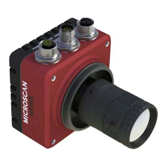
- Page 1 HAWK MV-4000 Smart Camera Guide 84-9007433-02 Rev A...
-
Page 2: Technical Support
The information and specifications described in this manual are subject to change without notice. Latest Manual Version For the latest version of this manual, see the Download Center on our web site at: www.microscan.com. Technical Support For technical support, e-mail: Americas_support@microscan.com... - Page 3 Statements of Compliance HAWK MV-4000 Smart Cameras have been tested for compliance with FCC (Federal Communications Commission) requirements and have been found to conform to applicable FCC standards. To comply with FCC RF exposure compliance requirements, this device must not be co-located with or operate in conjunction with any other antenna or transmitter.
-
Page 4: Fcc Compliance Statement
Bitte wenden Sie sich an dem Microscan-Website (www.microscan.com) für Recycling Informationen. (Italiano) Informazioni per gli utenti europei – Direttiva sui rifiuti di apparecchiature elettriche ed elettroniche (RAEE) Si prega di riferirsi al sito Web Microscan (www.microscan.com) per le informazioni di riciclaggio. -
Page 5: Symbol Description
HAWK MV-4000 Safety Warnings and Symbols Key Before using the HAWK MV-4000 Smart Camera, you should be aware of the meanings of the safety warnings and symbols on the device. The following is a list of HAWK MV-4000 symbols and their meanings. -
Page 6: Table Of Contents
Ground and Shield Considerations 2-38 Electrical and I/O Specifications 2-40 Environmental Specifications 2-41 Status Indicators 2-42 Adding a HAWK MV-4000 to a Network 2-43 Setting Up a Job in AutoVISION 2-44 Trigger Debounce 2-49 Setting Up Partial Scan 2-51 CHAPTER 3... - Page 7 APPENDIX G Operating System Save and Restore G-1 Restore to Microscan Factory Settings G-2 Access Microscan Rescue Utility G-7 Back Up/Restore/Capture the OS Image with Microscan Rescue Utility G-11 APPENDIX H OS Config Application H-1 Global Settings Tab H-2 Write Filter Tab H-3...
-
Page 8: Preface
This manual contains detailed information about how to configure and operate the HAWK MV-4000 Smart Camera. Manual Conventions • Items emphasizing important information are bolded. • Menu selections, menu items, and entries in screen images are indicated as: Run (triggered), Modify..., etc. HAWK MV-4000 Smart Camera Guide viii... -
Page 9: Introduction
Introduction CHAPTER 1 HAWK MV-4000 Smart Camera HAWK MV-4000 Smart Camera Guide... -
Page 10: Product Summary
The processor is a Dual-Core Intel Celeron N2807 with 2 GB of RAM and 32 GB of eMMC (flash disk) storage memory. The HAWK MV-4000 is able to store, load, and run up to 50 simple or complex jobs. Processing times reach near-PC speeds, enabling the camera to keep up with line rates of up to 6,000 parts per minute and speeds of over 300 inches per second. -
Page 11: Features And Benefits
APIs, and serial command set; • HMI via VGA and USB connectivity, or via web using CloudLink UI; • Scalable down to Microscan’s MicroHAWK MV Smart Camera; • Scalable up to Microscan’s Multi-GigE Camera PC-Based Systems. HAWK MV-4000 Smart Camera Guide... -
Page 12: Applications
Fast inline 1D and 2D symbol verification and validation; • Color inspection and verification. Package Contents Before you install AutoVISION Software and connect the HAWK MV-4000 Smart Camera, please take a moment to confirm that the following items are present: • HAWK MV-4000 Smart Camera;... -
Page 13: Hawk Mv-4000 Smart Camera Models
HAWK MV-4000 Smart Camera Models HAWK MV-4000 Smart Camera Models The table below lists and describes the basic HAWK MV-4000 Smart Camera models not including lenses, lens caps, accessories, and lighting. PPP at the end of each part number represents the license level. Each model can be ordered with one of the following five license levels: 100 –... -
Page 14: Hawk Mv-4000 Part Number Structure
Chapter Introduction HAWK MV-4000 Part Number Structure HAWK MV-4000 part numbers follow the format 8ABS-LFFA-LPPP. 8 = HAWK MV-4000 Smart Camera (A) Enclosure 0 = No Lens Cover 1 = 50 mm Lens Cover 2 = 70 mm Lens Cover... -
Page 15: System Components
System Components CHAPTER 2 This section contains specific information about system components as well as information to help you connect your HAWK MV-4000 Smart Camera. Note: There are no user-serviceable parts inside the camera. HAWK MV-4000 Smart Camera Guide... -
Page 16: Hardware Components And Accessories
8011-0000-0103 HAWK MV-4000-03, 0.3 Megapixel (640 x 480), Mono, AutoVISION + Verification / OCV 8011-0000-0104 HAWK MV-4000-03, 0.3 Megapixel (640 x 480), Mono, AutoVISION + Visionscape + Verification / OCV 1.3 Megapixel Mono 8012-0000-0100 HAWK MV-4000-13, 1.3 Megapixel (1280 x 1024), Mono, AutoVISION Sensor 8012-0000-0101 HAWK MV-4000-13, 1.3 Megapixel (1280 x 1024), Mono, AutoVISION... - Page 17 8017-0000-0103 HAWK MV-4000-20C, 2.0 Megapixel (1920 x 1200), Color, AutoVISION + Verification / OCV 8017-0000-0104 HAWK MV-4000-20C, 2.0 Megapixel (1920 x 1200), Color, AutoVISION + Visionscape + Verification / OCV 5.0 Megapixel Color 8018-0000-0100 HAWK MV-4000-50C, 5.0 Megapixel (2592 x 2048), Color, AutoVISION Sensor 8018-0000-0101 HAWK MV-4000-50C, 5.0 Megapixel (2592 x 2048), Color, AutoVISION...
- Page 18 Trigger Connector, 4-Pin Plug (Screw Terminal, Field-Wireable) (Self-Wiring) Smart Series Illuminator Control Cables 61-9000135-01 Y Cable, HAWK MV-4000 Adapter to Smart Series Illuminator and QX-1, Power, 1 m 61-9000137-01 Y Cable, HAWK MV-4000 Adapter to Smart Series Illuminator and QX-1, Strobe, 1 m...
- Page 19 1.3 Megapixel, High Resolution Lens 8212-2160-0104 HAWK MV-4000-13, AutoVISION + Visionscape + Ver. / OCV, 16 mm High Res. Lens, IP Cover, Universal Mount 8212-2250-0104 HAWK MV-4000-13, AutoVISION + Visionscape + Ver. / OCV, 25 mm High Res. Lens, IP Cover, Universal Mount 8212-2350-0104 HAWK MV-4000-13, AutoVISION + Visionscape + Ver.
-
Page 20: Hawk Mv-4000 Dimensions
Chapter System Components HAWK MV-4000 Dimensions Standard HAWK MV-4000 Front HAWK MV-4000 Smart Camera Guide... - Page 21 HAWK MV-4000 Dimensions Standard HAWK MV-4000 Back HAWK MV-4000 Smart Camera Guide...
- Page 22 Chapter System Components Standard HAWK MV-4000 Side HAWK MV-4000 Smart Camera Guide...
- Page 23 HAWK MV-4000 Dimensions Standard HAWK MV-4000 Base HAWK MV-4000 Smart Camera Guide...
-
Page 24: Label Information
Chapter System Components Label Information Each HAWK MV-4000 Smart Camera has a label that contains important information about that camera. • M/N: The model name of the camera. • P/N: The Microscan part number of the camera. • MAC: The MAC address of the camera. -
Page 25: Mounting, Connecting, And Wiring
Mount the camera (1) securely as required by the application. Mounting holes (M4x0.7 thread, 4 mm deep) Universal Mount and APG Mount ¼-20 tripod mounting hole Adapter to standard APG mount. Mounts on standard tubing with 6 mm hardware. HAWK MV-4000 Smart Camera Guide 2-11... - Page 26 • 100/1000 Base-T Connector. Provides connectivity between the HAWK MV-4000 and your computer or your network. The HAWK MV-4000 can gain access to a LAN via Gigabit Ethernet (GigE, 1G Base-T, or 1000Base-T), fast Ethernet (100Base-T), or twisted pair Ethernet (10Base-T).
- Page 27 Lens Extension Tube Set, 0.5 mm, 1 mm, 5 mm, 10 mm, 20 mm, 40 mm 98-CO206 Cable, HAWK MV-4000 Ethernet, X-CODE / RJ45 CAT 6A, 1 m, 3 m, or 5 m 61-9000134-0X Cable, HAWK MV-4000 M12 to USB Socket or VGA / USB, 1 m...
- Page 28 Output Common Red/Blue Analog Output Black Output 3 Pink Power Brown Trigger White Input Common Input 2 Green Input 3 Violet Input 1 Yellow Output 1 Gray Ground Blue Output 2 Gray / Pink 2-14 HAWK MV-4000 Smart Camera Guide...
- Page 29 Mounting, Connecting, and Wiring Ethernet Configuration with QX-1 and NERLITE Smart Series Illuminator NERLITE Smart Series Illuminator Power Supply Photo (12-Pin Socket) Sensor HAWK MV-4000 Smart Camera Guide 2-15...
- Page 30 Chapter System Components Ethernet Configuration, Y Cable for Illuminator Control and Camera Power NERLITE Smart Series Illuminator NERLITE Smart Series Illuminator NERLITE Smart Series Illuminator Power Supply (12-Pin Socket) 2-16 HAWK MV-4000 Smart Camera Guide...
-
Page 31: Connecting To The I/O Interface
One input is dedicated as the camera trigger (sensor). The other three are configurable general-purpose inputs. When the HAWK MV-4000 is used with the QX-1 interface device and photo sensor, the trigger signal is automatically connected to the correct input channel. - Page 32 A sourcing device provides a path that sources current; it provides a path from the power source. In the following diagram, the device on the right is the sourcing device, and the device on the left is the sinking device. (Equivalent circuit only.) 2-18 HAWK MV-4000 Smart Camera Guide...
- Page 33 Connecting to the I/O Interface Connecting Devices to Output Signals HAWK MV-4000 output signals can be interfaced with input modules (with sourcing or sinking input signals) found on most programmable logic controllers (PLCs) and other devices. The output signals can also be interfaced with inductive load devices (such as a relay, light stack or a small motor).
- Page 34 Output pin is attached to a power source or a sourcing device. When an output signal is off, the circuit between the Output pin and the Output Common pin is opened and no current flows through. Important: The power source must be provided externally. 2-20 HAWK MV-4000 Smart Camera Guide...
- Page 35 A resistance value of 3 KOhms is suggested to protect your HAWK MV-4000. Since your HAWK MV-4000 output signals can sink up to 50 mA, use the documentation of your input to calculate the required resistance for your external pull-up/pull-down resistor (if necessary).
- Page 36 HAWK MV-4000 can safely transmit. If more than 50 mA of current goes through your HAWK MV-4000, the fuse will eventually trip. After disconnecting your HAWK MV-4000, the fuse will reset only after it has sufficiently cooled.
- Page 37 The HAWK MV-4000 output signals are optically isolated from the power and analog reference signal as well as from the HAWK MV-4000 input signals. They are not, however, optically isolated from each other as they share a common pin (Output Common).
- Page 38 Chapter System Components Connecting an Output Signal To a Sourcing Input Connect a HAWK MV-4000 output signal to a sourcing input, as shown below. (Equivalent circuit only.) Note: When connecting a resistive load sourcing device instead of an input sensing sourcing device, the same connection would be used as displayed above.
- Page 39 Connecting to the I/O Interface Connecting an Output Signal To a Sinking Input Connect a HAWK MV-4000 output signal to a sinking input, as shown below. In this case, the pull-up circuitry is used to source the current to the sinking input.
- Page 40 Note that, in this configuration, you will need to connect an external pull-up resistor. Since your HAWK MV-4000 output signals can sink up to 50 mA, use the documentation of your sinking device to calculate the required resistance for your external pull-up resistor (if necessary).
- Page 41 Connecting to the I/O Interface Connecting an Output Signal to an Inductive Load Input To connect a HAWK MV-4000 output signal to an inductive load input, follow the diagram as shown below. An inductive load device, such as a traditional relay, requires that you use a flyback diode to protect HAWK MV-4000 from over and under-voltage, as shown below.
- Page 42 System Components Connecting Devices to the Input Signals HAWK MV-4000 input signals can be interfaced with a wide variety of devices (such as proximity detectors). The HAWK MV-4000 input signals only detect when current flows between their Input pin and Input Common pin. As such, an input signal must be connected to a device that controls the flow of current.
- Page 43 In this case, select a resistor value that will not overcurrent the output device and instead provide just enough current and voltage to your HAWK MV-4000 input signals, according to the electrical specifications subsection in Appendix C: General Specifications. Note that you should use a resistor with an appropriate power rating for your circuit.
- Page 44 The following subsections detail how to connect the most common third-party devices to the HAWK MV-4000 input signals. Note that HAWK MV-4000 input signals are optically isolated. Ground is only shown in the following subsections for reference, in case you need to reference your return path to ground.
- Page 45 Connecting to the I/O Interface Connecting a Sourcing Output Device to an Input Signal Connect a sourcing output device to HAWK MV-4000 input signal, as shown below. (Equivalent circuit only.) HAWK MV-4000 Smart Camera Guide 2-31...
- Page 46 Chapter System Components Connecting a Sinking Output Device To an Input Signal Connect a sinking output device to a HAWK MV-4000 input signal, as shown below. (Equivalent circuit only.) 2-32 HAWK MV-4000 Smart Camera Guide...
- Page 47 Connecting to the I/O Interface Connecting a 3-Wire PNP Proximity Sensor to an Input Signal Connect a 3-wire PNP proximity sensor to a HAWK MV-4000 input signal, as shown below. (Equivalent circuit only.) HAWK MV-4000 Smart Camera Guide 2-33...
- Page 48 Chapter System Components Connecting a 3-Wire NPN Proximity Sensor to an Input Signal Connect a 3-Wire NPN proximity sensor to a HAWK MV-4000 input signal, as shown below. (Equivalent circuit only.) 2-34 HAWK MV-4000 Smart Camera Guide...
- Page 49 Connecting a 2-Wire Proximity Sensor to an Input Signal You can connect a 2-wire proximity sensor to a HAWK MV-4000 input signal in either a sourcing or sinking configuration (that is, on a positive or negative power wire). Note that in both cases, you will need to install an external bleeder resistor, to ensure that a minimum amount of current flows into the proximity sensor in its on-state and in its off- state.
- Page 50 For the input signal to sink the current, connect the 2-wire device to input signal as shown below. Install the external bleeder resistor between the blue wire of the proximity sensor and the Input Common pin. (Equivalent circuit only.) 2-36 HAWK MV-4000 Smart Camera Guide...
-
Page 51: Input/Output Wiring Using Flying Lead Cable 61-9000151-01
Output Common Red/Blue Analog Output Black Output 3 Pink Power Brown Trigger White Input Common Input 2 Green Input 3 Violet Input 1 Yellow Output 1 Gray Ground Blue Output 2 Gray / Pink HAWK MV-4000 Smart Camera Guide 2-37... -
Page 52: Ground And Shield Considerations
Ground loops (signal degradation due to different ground potentials in communicating devices) can be eliminated or minimized by ensuring that both the host, imager, and their power supplies are connected to a common earth ground. 2-38 HAWK MV-4000 Smart Camera Guide... - Page 53 “2-Terminal Power Supply” must still provide an “Earth” connection to the imager. • “Signal Ground” can be used for communications and/or discrete signal ground reference. It must not be used as Power Ground or Earth Ground. HAWK MV-4000 Smart Camera Guide 2-39...
-
Page 54: Electrical And I/O Specifications
Minimum input current at min. ON voltage. Can be used to calculate bleeding resistor needed for 2-wire proximity sensor. f. Recommended > 12 V when using HAWK MV-4000 breakout board. 2-40 HAWK MV-4000 Smart Camera Guide... -
Page 55: Environmental Specifications
Operating temperature: 0° to 50° C (32° F to 122° F) • Ventilation requirements: Natural convection • Pollution degree: 2 environment • Over-voltage category: I • Ingress protection rating: IP67 1. Under current testing conditions. HAWK MV-4000 Smart Camera Guide 2-41... -
Page 56: Status Indicators
Chapter System Components Status Indicators The base of the HAWK MV-4000 Smart Camera has multiple LEDs that indicate different power, status, user, and communication states. The HAWK MV-4000 LEDs are: • POWER and USER. The colors of these two LEDs change as your HAWK MV-4000 boots up. -
Page 57: Adding A Hawk Mv-4000 To A Network
The last four hexadecimal digits of your HAWK MV-4000’s MAC address are used as the numeric part of the device name. Both the network name of your HAWK MV-4000 and its MAC address are written on a sticker on your HAWK MV-4000. Note that, when dealing with the Windows version, the device name is also known as the computer name. -
Page 58: Setting Up A Job In Autovision
Mount and connect the HAWK MV-4000 hardware. Plug in the power supply. Select your HAWK MV-4000 in the AutoVISION Connect view, create a job, and adjust camera settings. AutoVISION's Connect view allows you to select your device and configure its settings, and to create a new job. - Page 59 Important: When modifying camera settings, you will need to enter a username and password for the camera if a password has been defined. Note: The HAWK MV-4000’s default IP address is: 192.168.AA.BB where AA.BB are the last 2 octets in decimal of the device MAC Address with subnet Class B 255.255.0.0.
- Page 60 Image view. This view allows you to Auto Calibrate the camera, and to manually adjust the camera's Exposure, Gain, and Focus, and also to set the Lighting Mode (On, Off, or Strobe). 2-46 HAWK MV-4000 Smart Camera Guide...
- Page 61 Trigger, and Lighting. Inspection Outputs options allow you to connect your job to the outside world. This is also the view where you can add multiple tools to the job. The tool icons are located above the main view area. HAWK MV-4000 Smart Camera Guide 2-47...
- Page 62 Going to the Run view will automatically download your job to the camera and start it running. Save the Job. Click the Save to Camera icon on the File menu bar to save the job to the camera. 2-48 HAWK MV-4000 Smart Camera Guide...
-
Page 63: Trigger Debounce
IO Line Debounce High Time 100 //usecs (valid range: 0 to 268432 such that debounce time * 1000 must be divisible by 16) IO Line Debounce Low Time 100 //usecs (valid range: 0 to 268432 such that debounce time * 1000 must be divisible by 16) HAWK MV-4000 Smart Camera Guide 2-49... - Page 64 // Controllable shutter time. Usually using a pulse width specified in usecs Usecs Per Frame 16667 // Fastest time to acquire a frame: 60 FPS for HAWK MV-4000 CMOS Camera // -1 Disables timeout feature // IO Configuration GPIO Edit Mask 0x0000...
-
Page 65: Setting Up Partial Scan
• Stride: This value must be a multiple of 32. • Rows: This value must be a multiple of 2. Minimum size X of 32. Maximum value to whole sensor size. Minimum size Y of 2. Maximum value to whole sensor size. HAWK MV-4000 Smart Camera Guide 2-51... - Page 66 Chapter System Components 2-52 HAWK MV-4000 Smart Camera Guide...
-
Page 67: Lighting
Lighting CHAPTER 3 This section describes HAWK MV-4000 Smart Camera illumination options. HAWK MV-4000 Smart Camera Guide... -
Page 68: Illumination
Lighting Illumination The HAWK MV-4000 Smart Camera is a C-Mount camera and is used with external lighting. Any lighting can be used, but the HAWK MV-4000 comes with accessories and cables that allow it to connect directly with Microscan’s NERLITE Smart Series lights. Software control allows the lights to be operated in multiple modes: Off, Continuous, and Strobe. -
Page 69: External Illumination Control And Wiring
External Illumination Control and Wiring External Illumination Control and Wiring The HAWK MV-4000 Smart Camera supports external lighting with Microscan’s NERLITE Smart Series lights. The diagrams below demonstrate how the camera and light can be configured with the QX-1 interface device and light kit Y-cables. The light is controlled using the lighting control in AutoVISION Software’s camera configuration settings. - Page 70 Chapter Lighting HAWK MV-4000 and Smart Series Light Configuration: Y-Cable Item Description Part Number Smart Series Light NER-011660XXXG Assembly, Cable, QX-1 to Smart Series and Camera, Power 61-9000135-01 Assembly, Cable, QX-1 to Smart Series and Camera, On/Off 61-9000136-01 Assembly, Cable, QX-1 to Smart Series and Camera, Strobe...
-
Page 71: Selecting A Lens
Selecting a Lens APPENDIX A This section contains information about choosing the best lens to suit your application. HAWK MV-4000 Smart Camera Guide... -
Page 72: Lens Selection
Lens Selection This section includes information on lens selection, an important consideration when building your application. The HAWK MV-4000 comes accessorized with a variety of lens types and sizes to aid you in solving your application challenges. Choosing the Correct Lens Size for the Application The primary consideration during lens selection is that the focal length of the selected lens meets your application’s requirements. - Page 73 Blurred Image Created with a Lower-Quality, Lower-Cost Lens Not Matched to Pixel Size Crisp Image Created with a Higher-Quality, Higher-Cost Lens Matched to Pixel Size The HAWK MV-4000 sensors all have a pixel size of 4.8 microns. The standard HAWK MV-4000 comes with 3 lens types: •...
-
Page 74: Lens Specifications
F4/25MM, 2/3", I2C INTERFACE 50 mm 4.0 2/3" 98-9000179-01 KIT, LENS, LIQUID, C-MOUNT, F2.8/16MM, 2/3", I2C INTERFACE 50 mm 2.8 2/3" IP Cover 98-9000155-01 Kit, IP Cover, 50 mm 98-9000156-01 Kit, IP Cover, 70 mm HAWK MV-4000 Smart Camera Guide... -
Page 75: Cable Specifications
Cable Specifications APPENDIX B This section contains information about HAWK MV-4000 Smart Camera cables. Note: Cable specifications are published for information only. Microscan does not guarantee the performance or quality of cables provided by other suppliers. Part Number Description 61-9000132-01... -
Page 76: 61-9000132-01 Cable, Adapter, Hawk Mv-4000 To
HAWK MV-4000 Cables 61-9000132-01 Cable, Adapter, HAWK MV-4000 to QX-1 The 61-9000132-01 Cable, Adapter, HAWK MV-4000 to QX-1 allows the HAWK MV-4000 to be connected to the QX-1 accessory and any Microhawk M12 accessory cables. The cable is directional and must be connected as labeled for proper function and to avoid potential damage to the camera. -
Page 77: 61-9000134-0X Cable, Ethernet, X-Code/Rj45 Cat 6A, 1 M, 3 M, 5 M
61-9000134-0X Cable, Ethernet, X-Code/RJ45 CAT 6A, 1 m, 3 m, 5 m The 61-9000134-01, -02, and -03 Cable, Ethernet, X-Code/RJ45 CAT 6A, 1m, 3m, 5m, respectively has an X-Code M12 Ethernet connector on one end and standard RJ45 on the other. HAWK MV-4000 Smart Camera Guide... -
Page 78: M12 To Smart Series And Camera Cables
61-9000136-01 Cable, M12 to Smart Series and Camera, On/Off, 1 m • 61-9000137-01 Cable, M12 to Smart Series and Camera, Strobe, 1 m The M12 connector on the input side can then be connected directly to a flying leads cable or other control device. HAWK MV-4000 Smart Camera Guide... -
Page 79: 97-000012-01 Power Supply, M12 12-Pin Socket, 1.3 M
HAWK MV-4000 Cables 97-000012-01 Power Supply, M12 12-Pin Socket, 1.3 m The 97-000012-01 Power Supply, M12 12-pin Socket, 1.3 m is a 90-254 VAC, +24VDC power supply. M12 12-Pin Socket HAWK MV-4000 Smart Camera Guide... -
Page 80: 99-000020-02 Trigger, M12 4-Pin Plug, Npn, Dark On, 2 M
Appendix Cable Specifications 99-000020-02 Trigger, M12 4-Pin Plug, NPN, Dark On, 2 m The 99-000020-02 Trigger, M12 4-pin Plug, NPN, Dark On, 2 m is a photo sensor with a 4-pin M12 connector. 99-000020-02 Schematic HAWK MV-4000 Smart Camera Guide... -
Page 81: General Specifications
General Specifications APPENDIX C This section contains specifications for the HAWK MV-4000 Smart Camera. HAWK MV-4000 Smart Camera Guide... -
Page 82: Sensor Board
Frame rate is established solely upon rates of acquisition. Your results will differ when including processing time. b. Note that these numbers come from tests that store the grabbed images in BGR packed format. When using YUV, planar, or Mono10 packed formats, the frame rate can be significantly different. HAWK MV-4000 Smart Camera Guide... -
Page 83: Cpu Board
• Display: Your HAWK MV-4000 provides a VGA/USB output to connect a monitor, keyboard, and mouse directly to the device or connect a touch display to the device. Note that a standard USB keyboard and mouse are supported natively. To connect any other device (such as a specialized keyboard or touch screen) to your HAWK MV-4000, it may require a specialized device driver. -
Page 84: Vga/Usb Port
Instead, use a can of compressed air or a lens cleaning cloth to remove dust. The HAWK MV-4000 works with the Varioptic Caspian C-39N0-160-I2C or C-39N0-250- I2C lens (liquid lens). This electronically focus-controllable C-mount lens fits within the optional IP lens case. -
Page 85: Electrical Specifications
Maximum input current at max. ON voltage. The connected device must not limit the current to a value lower than this. e. Minimum input current at min. ON voltage. Can be used to calculate bleeding resistor needed for 2-wire proximity sensor. f. Recommended > 12 V when using HAWK MV-4000 breakout board. HAWK MV-4000 Smart Camera Guide... -
Page 86: Environmental Specifications
Over-voltage category: I • Ingress protection rating: IP67 Mechanical Specifications HAWK MV-4000-03, -03C, -13, -13C, -20, -20C, -50, -50C M12 8-pin connector for 100/1000 Base-T Ethernet. Connectors M12 12-pin plug connector for VGA/USB. M12 12-pin socket connector for digital I/O and power. -
Page 87: Dimensions
HAWK MV-4000 General Specifications Dimensions Dimensions HAWK MV-4000-03, -03C, -13, -13C, -20, -20C, -50, -50C Weight 460.39 g (16.24 oz) Length (without connectors) 75 mm (2.95") x 75 mm (2.9"‘) ± 2 mm (0.079") Height (without lens) 54 mm (2.13") ± 2 mm (0.079") Width 75 mm (2.95") ±... -
Page 88: Digital I/O And Power Adapter Cable Connector
Appendix General Specifications HAWK MV-4000 Connectors The HAWK MV-4000 has several interface connectors. These are the digital I/O and power connector, 100/1000 Base-T connector, the VGA/USB connector, and the liquid lens connector. Digital I/O and Power Adapter Cable Connector The digital I/O and power connector of the adapter cable is an M12 12-pin plug connector that transmits and receives digital I/O signals, provides an analog reference voltage for an inline control system lighting controller, and provides power to your HAWK MV-4000. - Page 89 Output 1 Ground Output 2 To interface with this adapter cable connector, you can use either a Microscan accessory cable or you can build your own. To build your own digital I/O and power cable, parts can be purchased from:...
-
Page 90: 100/1000 Base-T Connector
Bidirectional data C– MDI_3+ Bidirectional data C+ To interface with this connector, you can use either a Microscan accessory cable or you can purchase a similar cable from an alternate source. For an alternate source of 100/1000 Base-T cables, contact:... -
Page 91: Vga/Usb Connector
640 x 480 85 Hz The pinout for the VGA/USB connector is as follows: Signal Name Description USB PWR 5 V supplied from your HAWK MV-4000 to USB peripherals. USB_DATA_P USB data + USB_DATA_N USB data – USB_REF USB reference... - Page 92 General Specifications The following is a wire-diagram of the VGA/USB cable, showing the connection between the HAWK MV-4000 VGA/USB connector on one end and the HD-15 and USB connectors on the other. This cable can be purchased separately from Microscan (61-9000147-01). A USB only cable (no VGA connector) can also be purchased from Microscan (61-9000143-01).
-
Page 93: Liquid Lens Connector
Varioptic Caspian C-39N0-160-I2C or C-39N0-250-I2C lens. The secondary, 3-pin plug connector from the Varioptic lens is not used. This connector is located inside the lens cap housing of the HAWK MV-4000. The pinout for the liquid lens connector is as follows:... - Page 94 Appendix General Specifications C-14 HAWK MV-4000 Smart Camera Guide...
-
Page 95: Mvmonitor Web Page
MVMonitor Web Page APPENDIX D This section explains how to connect to the MVMonitor web page and how to interpret the information displayed there. HAWK MV-4000 Smart Camera Guide... -
Page 96: Using The Mvmonitor Web Page
MVMonitor Web Page Using the MVMonitor Web Page The HAWK MV-4000 Smart Camera provides a “health status” web page that can be viewed in a web browser of your choice. General information about the camera’s network identity and the state of the runtime is provided. To connect to the page, simply enter the name of your camera at the specific port 8088. - Page 97 "Access Log Files" Link: Clicking this link will take you to an FTP page where you can download any of the log files to your local PC. Launch CloudLink Clicking Launch CloudLink opens the HAWK MV-4000 Smart Camera’s web-based runtime monitoring interface in a separate browser tab. More information about CloudLink can be found in Appendix E: CloudLink Web HMI.
- Page 98 Appendix MVMonitor Web Page HAWK MV-4000 Smart Camera Guide...
-
Page 99: Cloudlink Web Hmi
This appendix contains information about CloudLink support for the HAWK MV-4000. Refer to Getting Started with CloudLink – installed in the documentation folder C:\Microscan\Vscape\Documentation during AutoVISION/Visionscape installation – for detailed information about configuring and using the CloudLink web HMI. -
Page 100: Connecting
For example, if you have a Microscan smart camera on your network at address 10.20.1.123, you would enter: If using a HAWK MV-4000, you can also type the name of the device, as in the example http://HAWK5E7420. The HAWK MV-4000 has a dedicated VGA/USB connector for attaching either a touch monitor or regular monitor with keyboad and mouse. -
Page 101: Application Overview
API. When memory is full, the camera will first delete full-size images, then thumbnails, and ultimately the data records on a first in-first out basis. This is a typical view of a CloudLink page. HAWK MV-4000 Smart Camera Guide... -
Page 102: Application Bar
A logo. The position and contents of the logo can be customized. • A toolbar. The toolbar provides access to various CloudLink settings and modes. The position and size of the toolbar can be customized. HAWK MV-4000 Smart Camera Guide... -
Page 103: Pages, Panels, And Widgets
The purpose of the panels is to act as containers for a number of widgets. Each widget has the ability to visualize and interact with one or more items of inspection data such as Microscan Link values, inspection counters, timing information, or images. HAWK MV-4000 Smart Camera Guide... - Page 104 Appendix CloudLink Web HMI Each panel has special layout and behavior properties that can be exploited to create a wide variety of different layouts. The following table summarizes the position and properties of each panel: HAWK MV-4000 Smart Camera Guide...
- Page 105 Pages, Panels, and Widgets If a panel does not have content (i.e. no widgets are placed in it), it is hidden from view, with the other panels adjusted to occupy the available space. Examples of possible page layouts: HAWK MV-4000 Smart Camera Guide...
- Page 106 Appendix CloudLink Web HMI HAWK MV-4000 Smart Camera Guide...
-
Page 107: Serial Commands
Serial Commands APPENDIX F This section provides descriptions of the serial commands that can be sent to the camera via TCP (Telnet) port, AutoVISION Terminal, or HyperTerminal. HAWK MV-4000 Smart Camera Guide... - Page 108 Success Return: On success will return the value stored in the tag. For example: ABCD Fail Return: On failure will return !ERROR followed by the reason for the failure. For example: !ERROR Tag matchstring66 not found HAWK MV-4000 Smart Camera Guide...
- Page 109 Initiates serial transfer of inspection image (RS-232 only). Note: This command always returns the last (most recent) image. Important: This command is only supported over TCP/IP for the HAWK MV-4000. -transfer=ymodem is currentlynot optional - only Ymodem protocol is supported.
- Page 110 Important: Does not delete the current job loaded in camera memory. JOBDOWNLOAD <-transfer={ymodem|ftp}> [-size=value] [-c] Important: This command is only supported over TCP/IP for the HAWK MV-4000. Downloads a .avz job file via the specified transfer method (ymodem supported only over RS-232;...
- Page 111 Queries if inspection is waiting for a trigger. Defaults to first inspection is not specified. REBOOT [-noload] Reboots the device. -noload = do not load BOOT job. RESTOREWBAL Restores preset white balance parameters: RED gain, BLUE gain, and GREEN gain. HAWK MV-4000 Smart Camera Guide...
- Page 112 Sets units used for autofocus, mm (0) or inches (1). TARGET {0|1|off|on} Turns targeting LEDs On or Off. target 1 = Turn Target On target 0 = Turn Target Off TRIGGER Triggers an inspection. VERSION Returns Visionscape software version. HAWK MV-4000 Smart Camera Guide...
- Page 113 Fail Return: Return !ERROR followed by the reason for the failure. For example: !ERROR No such trigger when the index specified ‘n’ is out of range of virtual triggers. WHITEBAL Performs automatic calibration of white balance settings: RED gain, BLUE gain, and GREEN gain. HAWK MV-4000 Smart Camera Guide...
- Page 114 Appendix Serial Commands HAWK MV-4000 Smart Camera Guide...
-
Page 115: Operating System Save And Restore
Restore This section provides instructions on how to back up and restore the HAWK MV-4000’s operating system. A recovery USB key with the name “Microscan HAWK Recovery” is provided with each camera. This section describes in detail the process for saving and restoring the device’s operating system. -
Page 116: Restore To Microscan Factory Settings
To restore your HAWK MV-4000 to factory settings, do the following: The HAWK MV-4000 is delivered with an OS Rescue USB KEY. Insert the USB key into your HAWK MV-4000. You may require a USB hub to make this connection so you can add a keyboard and mouse. - Page 117 Restore to Microscan Factory Settings The Microscan ResQDisk Utility will appear shortly. Click Next. Click I agree at the Software License Terms screen. HAWK MV-4000 Smart Camera Guide...
- Page 118 Appendix Operating System Save and Restore Click Restore OS. Click Yes selection box, then Next. HAWK MV-4000 Smart Camera Guide...
- Page 119 Restore to Microscan Factory Settings Open the dropdown to select the drive to restore, which should say: Disk:0, Model: Generic R1J58L, Size:28GB, click Next. Click Yes. All data on the camera will be lost. HAWK MV-4000 Smart Camera Guide...
- Page 120 Unplug and re-plug the device. The camera will now be restored to the FACTORY image. Click OK. After the unit has rebooted, log in. Plug in the HAWK Recovery USB key. Finally, restore your licenses and Jobs using Windows Explorer as documented in Restore to Microscan Factory Settings. HAWK MV-4000 Smart Camera Guide...
-
Page 121: Access Microscan Rescue Utility
Access Microscan Rescue Utility Access Microscan Rescue Utility If you can boot to Windows: Select the Start button, then choose Settings. Select Update and Security. HAWK MV-4000 Smart Camera Guide... - Page 122 Appendix Operating System Save and Restore Select Recovery. Under Advanced Startup select Restart Now. HAWK MV-4000 Smart Camera Guide...
- Page 123 Access Microscan Rescue Utility After your PC restarts to the Choose an Option screen, select Troubleshoot. Next select Microscan Rescue Utility. Follow steps 4 – 13 in the Restore to Microscan Factory Settings section. HAWK MV-4000 Smart Camera Guide...
- Page 124 If you can't boot to Windows: During system boot, press F8. This starts the Advanced Boot Options. Select Repair Your Computer. Follow steps 5 and 6 in the Access Microscan Rescue Utility section. G-10 HAWK MV-4000 Smart Camera Guide...
-
Page 125: Back Up/Restore/Capture The Os Image With Microscan Rescue Utility
Back Up / Restore / Capture the OS Image with Microscan Rescue Utility Back Up / Restore / Capture the OS Image with Microscan Rescue Utility The Microscan Rescue Utility offers three choices of operation: Restore OS. Backup/Capture OS. Copy Microscan Rescue Tool to USB storage device. - Page 126 Appendix Operating System Save and Restore After your PC restarts and displays the Choose an Option screen, select Troubleshoot. Select Microscan Rescue Utility. G-12 HAWK MV-4000 Smart Camera Guide...
- Page 127 Back Up / Restore / Capture the OS Image with Microscan Rescue Utility The Microscan Rescue Utility will display. Accept the License Agreement. HAWK MV-4000 Smart Camera Guide G-13...
- Page 128 OS partition). If you do not add a file name, the default file name will be W10HAWK.wim. Important: The device used to save the backup image should be formatted as NTFS. Click Go to save the image to your USB drive. G-14 HAWK MV-4000 Smart Camera Guide...
- Page 129 Back Up / Restore / Capture the OS Image with Microscan Rescue Utility When complete, you will see the following message: Click OK to shut down your device. Power down and then re-power the device. HAWK MV-4000 Smart Camera Guide...
- Page 130 To restore your backup image, do the following: Access the Microscan Rescue Utility. (See previous section.) Click Next to select Backup OS automatically. G-16...
- Page 131 Back Up / Restore / Capture the OS Image with Microscan Rescue Utility Click Back, then click Restore OS. Select your backup .wim file (W10HAWK.wim) from where you saved it, and select Disk 0 from the dropdown. Click Next. Note that these files are created with the backup option described later in this section.
- Page 132 Appendix Operating System Save and Restore Capture OS To customize your unit and deploy the same configuration to other HAWK MV-4000 cameras, do the following: After the Out-Of-Box-Experience (OOBE) completes, switch to Audit Mode as soon as possible. This allows you to keep the multiple language capability on other units.
- Page 133 Image or your customized image. For Microscan Factory Image: Insert the Microscan USB KEY corresponding to your OS version into a USB hub attached to your HAWK MV-4000 unit. Browse to location <USBKEY>\Ximage. For your Customized Image: Insert your source files (W10x64HAWK.wim file) into the USB port, browse to the location of the files.
- Page 134 Appendix Operating System Save and Restore G-20 HAWK MV-4000 Smart Camera Guide...
-
Page 135: Os Config Application
This application is used to determine OS and firmware versions, add and remove languages, turn on the hard drive write filter, show hard drive wear, show End User License Agreements, and capture your OS for backup of your system. HAWK MV-4000 Smart Camera Guide... -
Page 136: Global Settings Tab
Windows defender is disabled by default. You can enable it by clicking the Turn ON Windows Defender button. Windows updates are also disabled by default. You can enable them by clicking the ENABLE Windows Update button. HAWK MV-4000 Smart Camera Guide... -
Page 137: Write Filter Tab
Clicking DISABLE UWF disables the Windows Universal Write Filter again after reboot. The UWF is disabled by default. HAWK MV-4000 Smart Camera Guide... -
Page 138: Capture Os Tab
Appendix OS Config Application Capture OS Tab Operating System Save and Restore for more information about backing up the device. You can also click on the More info... button. HAWK MV-4000 Smart Camera Guide... -
Page 139: Languages Tab
Select to install or to uninstall using the Available Display Languages radio buttons, then select a language to add or remove from the device. Follow the screen prompts. Click the More info… button for instructions on enabling the language in Windows. Click Apply when ready. HAWK MV-4000 Smart Camera Guide... -
Page 140: Emmc Tab
This tab shows embedded Multi-Media Controller information. This is a display of the type of memory used for the hard drive. It shows statistics on the wear state of the actual hardware devices, and can warn of issues with them. HAWK MV-4000 Smart Camera Guide... -
Page 141: Eula Tab
EULA Tab EULA Tab This tab allows you to display the Microsoft and Microscan End User License Agreements. HAWK MV-4000 Smart Camera Guide... - Page 142 Appendix OS Config Application You must click I agree on each screen to acknowledge you understand the licensing terms. HAWK MV-4000 Smart Camera Guide...
Need help?
Do you have a question about the HAWK MV-4000 and is the answer not in the manual?
Questions and answers