Table of Contents
Advertisement
Quick Links
Advertisement
Table of Contents

Related Manuals for Microscan Vision HAWK GMV-6800-1000G


Summary of Contents for Microscan Vision HAWK GMV-6800-1000G
- Page 1 Vision HAWK Smart Camera Guide 83-016800-02 Rev C...
- Page 2 All rights reserved. The information contained herein is proprietary and is provided solely for the purpose of allowing customers to operate and/or service Microscan manufactured equipment and is not to be released, reproduced, or used for any other purpose without written permission of Microscan.
-
Page 3: Table Of Contents
Contents PREFACE Welcome! v Purpose of This Manual v Manual Conventions v CHAPTER 1 Introduction 1-1 Product Summary 1-2 Features and Benefits 1-2 Applications 1-3 Package Contents 1-3 Vision HAWK Smart Camera Models 1-4 Part Number Structure 1-4 CHAPTER 2 System Components 2-1 Hardware Components 2-1 Important Label Information 2-9... - Page 4 Contents APPENDIX A Connector Pinouts A-1 Vision HAWK Smart Camera Connectors A-2 APPENDIX B Cable Specifications B-1 61-000160-01 Cable, Host, Ethernet, M12 8-pin Plug to RJ45, 1 m B-2 61-000162-01 Cable, Common, M12 12-pin Plug to M12 12-pin Socket, 1 m B-3 97-000003-01 Power Supply, M12 12-pin Socket, 1.3 m B-4 99-000020-02 Trigger, M12 4-pin Plug, NPN, Dark On, 2 m B-5 APPENDIX C...
-
Page 5: Preface
Preface Welcome! PREFACE Purpose of This Manual This manual contains detailed information about the Vision HAWK Smart Camera. Manual Conventions The following typographical conventions are used throughout this manual. • Items emphasizing important information are bolded. • Menu selections, menu items and entries in screen images are indicated as: Run (triggered), Modify..., etc. - Page 6 Preface Vision HAWK Smart Camera Guide...
-
Page 7: Introduction
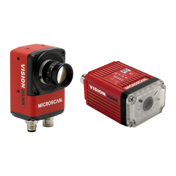
Introduction CHAPTER 1 Vision HAWK Smart Camera, C-Mount and Standard Models FIGURE 1–1. Vision HAWK Smart Camera Guide... -
Page 8: Product Summary
Chapter Introduction Product Summary The Vision HAWK Smart Camera is a compact industrial smart camera that provides powerful machine vision capabilities with a small form factor and intuitive software interface. The Vision HAWK is designed for industrial environments where IP65/67 enclosure and rugged M12 connectivity are required. -
Page 9: Applications
Applications Applications • Automotive assembly verification • Part identification • Label positioning • Contents verification • Electronics assembly verification and identification • Semiconductor packaging and component inspection • Auto ID (Data Matrix and other 2D symbologies, 1D, OCR) Package Contents Before you install AutoVISION software and connect your Vision HAWK Smart Camera, please take a moment to confirm that the following items are available:... -
Page 10: Vision Hawk Smart Camera Models
Chapter Introduction Vision HAWK Smart Camera Models Table 1–1 lists and describes the Vision HAWK Smart Camera models. Vision HAWK Smart Camera Models TABLE 1–1. Part Number Vision HAWK Smart Camera Model GMV-6800-1000G Vision HAWK, SXGA, AutoVISION, C-Mount GMV-6800-1002G Vision HAWK, SXGA, AutoVISION + Visionscape, C-Mount GMV-6800-1010G Vision HAWK, WVGA, AutoVISION, C-Mount GMV-6800-1012G... -
Page 11: System Components
System Components CHAPTER 2 This section contains information about system components as well as information to help you connect the Vision HAWK Smart Camera. Specific information describes connectors, adapters, cables, pinouts, and signals. Note: There are no user-serviceable parts inside. Hardware Components Table 2-1 lists Vision HAWK Smart Camera hardware components. - Page 12 Chapter System Components Vision HAWK Smart Camera Hardware Components (Continued) TABLE 2–1. Part Number Description GMV-6800-1100G Vision HAWK, SXGA, Built-In Light, AutoVISION, 15° Lens GMV-6800-1200G Vision HAWK, SXGA, Built-In Light, AutoVISION, 30° Lens GMV-6800-1300G Vision HAWK, SXGA, Built-In Light, AutoVISION, 45° Lens GMV-6800-1102G Vision HAWK, SXGA, Built-In Light, AutoVISION + Visionscape, 15°...
- Page 13 Hardware Components Vision HAWK Smart Camera Hardware Components (Continued) TABLE 2–1. Part Number Description 61-000167-01 Cordset, M12 12 Pin Socket (Ultralock) to Flying Leads, 3M 61-000167-02 Cordset, M12 12 Pin Socket (Screw-on) to Flying Leads, 3M 61-000207-01 Cordset, C-Mount-to-Smart Series Light FIS-0210-0001G MS-Connect 210, Connectivity Box with Display FIS-0210-0002G...
- Page 14 Photo Sensor, M12 4-pin Plug, NPN, Dark On, 2 m Documentation 37-000010-01 Microscan Tools Drive (Software, User’s Manuals, Quick Start Guides, Configuration Guides, links to other documents on Microscan website Note: Additional hardware components are available in the Microscan Product Pricing Catalog. Vision HAWK Smart Camera Guide...
- Page 15 Hardware Components Standard Vision HAWK Front Figure 2-1 shows the front of the Vision HAWK Smart Camera. Front FIGURE 2–1. Standard Vision HAWK Base Figure 2–2 shows the base of the Vision HAWK Smart Camera. Base FIGURE 2–2. Vision HAWK Smart Camera Guide...
- Page 16 Chapter System Components Standard Vision HAWK Side Figure 2-3 shows the side of the Vision HAWK Smart Camera. Side FIGURE 2–3. Standard Vision HAWK Back Figure 2-4 shows the back of the Vision HAWK Smart Camera. Back FIGURE 2–4. Vision HAWK Smart Camera Guide...
- Page 17 Hardware Components Vision HAWK C-Mount Front Figure 2-5 shows the front of the Vision HAWK C-Mount Smart Camera. Front FIGURE 2–5. Vision HAWK C-Mount Base Figure 2–6 shows the top of the Vision HAWK C-Mount Smart Camera. FIGURE 2–6. Vision HAWK Smart Camera Guide...
- Page 18 Chapter System Components Vision HAWK C-Mount Side Figure 2-7 shows the side of the Vision HAWK C-Mount Smart Camera. Side FIGURE 2–7. Vision HAWK C-Mount Back Figure 2-8 shows the back of the Vision HAWK C-Mount Smart Camera. Back FIGURE 2–8. Vision HAWK Smart Camera Guide...
-
Page 19: Important Label Information
Each Vision HAWK Smart Camera has its own label, which contains important information about that camera. • P/N – The Microscan part number of your Vision HAWK Smart Camera. • S/N — The serial number of your Vision HAWK Smart Camera. -
Page 20: Mounting And Wiring The Vision Hawk Smart Camera
Chapter System Components Mounting and Wiring the Vision HAWK Smart Camera • Mount the camera (1) securely as required by the application. Mounting holes • Connect the Ethernet cable (2) from “B” on the camera (1) to the network. • Connect the power supply cable (3) to “3”... - Page 21 Mounting and Wiring the Vision HAWK Smart Camera Optoisolated Outputs The reader has optoisolated outputs that can transfer signals from the camera to peripherals. Outputs can be configured as either NPN or PNP, but NPN and PNP cannot be mixed in a system, because the output common is shared by all outputs.
- Page 22 Chapter System Components NPN Output for External Load 2-12 Vision HAWK Smart Camera Guide...
- Page 23 Mounting and Wiring the Vision HAWK Smart Camera PNP Output for Host Input Vision HAWK Smart Camera Guide 2-13...
- Page 24 Chapter System Components PNP Output for External Load 2-14 Vision HAWK Smart Camera Guide...
- Page 25 Mounting and Wiring the Vision HAWK Smart Camera Optoisolated Inputs All discrete inputs are optoisolated. Inputs can be configured as either NPN or PNP, but NPN and PNP cannot be mixed in a system, because the input common is shared by all inputs. Vision HAWK Smart Camera Guide 2-15...
- Page 26 Chapter System Components 2-16 Vision HAWK Smart Camera Guide...
-
Page 27: Input/Output Wiring
Input/Output Wiring Input/Output Wiring Vision HAWK Smart Camera Guide 2-17... -
Page 28: Power Requirements
Chapter System Components Power Requirements Refer to Table 2-3 when determining the power supply requirements for your camera. Camera Power Requirements TABLE 2–3. Component Vision HAWK Smart Camera, CCD 5-28VDC, 200mV p-p max ripple, 170mA at 24VDC (typ.) 15.5 watts (max.) Vision HAWK Smart Camera, CMOS 5-28VDC, 200mV p-p max ripple, 135mA at 24VDC (typ.) -
Page 29: Status Indicators
Status Indicators Status Indicators The top of the Vision HAWK Smart Camera has multiple LEDs that indicate different trigger, inspection, camera, communication, and power states. TRIG = Trigger Status PASS/FAIL = Inspection Status Outputs 1, 2, 3 MODE = Camera Status Power Status LINK/ACT = Link Activity Status On Steady... -
Page 30: Autovision Button
Chapter System Components AutoVISION Button The AutoVISION Button has two positions, selectable by the length of time the button is held down, and indicated by one or two beeps in succession. It can also be used to send a trigger signal when Send Trigger is checked in AutoVISION software’s Connect view. -
Page 31: Setting Up A Job In Autovision
Power Supply, M12 12-pin Socket, 1.3 m 97-000003-01 Cordset, Host, Ethernet, M12 8-pin Plug to RJ45, 1 m 61-000160-01 Trigger, M12 4-pin Plug, NPN, Dark On, 2 m 99-000020-02 Note: Additional cables available in the Microscan Product Pricing Catalog. Vision HAWK Smart Camera Guide 2-21... - Page 32 Chapter System Components – Mount the camera as required by the application. – Connect the Ethernet cable from "B" on the camera to the network. – Connect the power supply to "3" on the QX-1. – Connect the photo sensor to "T" on the QX-1. –...
- Page 33 Connect view. Important: When modifying camera settings, you will need to enter a username and password for the camera. The default username and password are: – Username: Microscan – Password: vision Vision HAWK Smart Camera Guide 2-23...
- Page 34 Chapter System Components Once you have selected your camera, adjusted its settings, and created a new job, you will move to the Image view. This view allows you to Auto Calibrate the camera, and to manually adjust the camera's Exposure, Gain, and Focus, and also to set the Lighting Mode (On, Off, or Strobe).
- Page 35 Setting Up a Job in AutoVISION Run the Job in AutoVISION. Going to the Run view will automatically download your job to the camera and start it running. Save the Job. Click the Save to Camera icon on the File menu bar to save the job to the Vision HAWK.
- Page 36 Chapter System Components 2-26 Vision HAWK Smart Camera Guide...
-
Page 37: Optics And Lighting
Optics and Lighting CHAPTER 3 This section describes the optical and illumination characteristics of the Vision HAWK Smart Camera. Vision HAWK Smart Camera Guide... -
Page 38: Optics
Chapter Optics and Lighting Optics The Vision HAWK Smart Camera is available with a built-in CMOS sensor or CCD sensor. Optics Specifications Part Number GMV-6800- GMV-6800- GMV-6800- GMV-6800- GMV-6800- GMV-6800- 1100G 1200G 1300G 1110G 1210G 1310G Sensor CCD, Global Shutter CMOS, Global Shutter Sensor Color Monochrome... -
Page 39: Illumination
Illumination Illumination The standard version of the Vision HAWK Smart Camera has built-in lighting (red LEDs for SXGA models and white LEDs for QXGA models). The LEDs can be configured to operate in multiple modes – Continuous, Strobe, and Off. Lighting Specifications Part Number GMV-6800-... - Page 40 Proper lighting is critical to the success of a machine vision application. Depending on the requirements of your application, you may also need to add external lighting from Microscan’s NERLITE family of machine vision lighting products. Consider the following when setting up your application: –...
- Page 41 External Illumination Control The Vision HAWK C-Mount Smart Camera supports external lighting with Microscan’s NERLITE Smart Series lights. The diagram below demonstrates how the camera and light can be configured with two QX-1 interface devices. The light is controlled using the Lighting control in the Camera configuration settings of AutoVISION software.
- Page 42 Chapter Optics and Lighting Vision HAWK Smart Camera Guide...
-
Page 43: Connector Pinouts
Connector Pinouts APPENDIX A This section contains information about Vision HAWK Smart Camera connectors: • M12 12-Pin Plug on page A-2 • M12 8-Pin Socket on page A-3 Vision HAWK Smart Camera Guide... -
Page 44: Vision Hawk Smart Camera Connectors
Appendix Connector Pinouts Vision HAWK Smart Camera Connectors Connector A – M12 12-Pin Plug – Power, I/O, and Serial Figure A–1 shows the M12 12-pin plug at connector A. Connector A – M12 12-Pin Plug FIGURE A–1. Table A–1 describes the M12 12-pin plug signals. Connector A –... - Page 45 Vision HAWK Smart Camera Connectors Connector B – M12 8-Pin Socket – Ethernet Figure A-2 shows the M12 8-pin socket at connector B. Connector B – M12 8-Pin Socket FIGURE A–2. Table A-2 describes the M12 8-pin socket signals. Connector B – M12 8-Pin Socket TABLE A–2.
- Page 46 Appendix Connector Pinouts Vision HAWK Smart Camera Guide...
-
Page 47: Cable Specifications
Cable Specifications APPENDIX B This section contains information about Vision HAWK Smart Camera cables. Note: Cable specifications are published for information only. Microscan does not guarantee the performance or quality of cables provided by other suppliers. Cable Part Numbers and Descriptions TABLE B–1. - Page 48 Appendix Cable Specifications 61-000160-01 Cable, Host, Ethernet, M12 8-pin Plug to RJ45, 1 m The 61-000160-01 Cable, Host, Ethernet, M12 8-pin Plug to RJ45, 1 m is a 1 meter cable with an 8-pin M12 Ultra-Lock connector on one end and a standard RJ45 connector on the other end.
- Page 49 61-000162-01 Cable, Common, M12 12-pin Plug to M12 12-pin Socket, 1 m 61-000162-01 Cable, Common, M12 12-pin Plug to M12 12-pin Socket, 1 m The 61-000162-01 Cable, Common, M12 12-pin Plug to M12 12-pin Socket, 1 m is a 1 meter cable with a 12-pin M12 plug on one end and a 12-pin M12 socket on the other end.
- Page 50 Appendix Cable Specifications 97-000003-01 Power Supply, M12 12-pin Socket, 1.3 m The 97-000003-01 Power Supply, M12 12-pin Socket, 1.3 m is a 90-254 VAC, +24VDC power supply. Figure B-3 shows the 97-000003-01 Power Supply, M12 12-pin Socket, 1.3 m. Power Supply, M12 12-pin Socket, 1.3 m FIGURE B–3.
- Page 51 99-000020-02 Trigger, M12 4-pin Plug, NPN, Dark On, 2 m 99-000020-02 Trigger, M12 4-pin Plug, NPN, Dark On, 2 m The 99-000020-02 Trigger, M12 4-pin Plug, NPN, Dark On, 2 m is a photo sensor with a 4-pin M12 connector. Figure B-4 shows the 99-000020-02 Trigger, M12 4-pin Plug, NPN, Dark On, 2 m.
- Page 52 Appendix Cable Specifications Vision HAWK Smart Camera Guide...
-
Page 53: General Specifications
General Specifications APPENDIX C This section contains specifications and dimensions for the Vision HAWK Smart Camera and Vision HAWK C-Mount Smart Camera. General Specifications TABLE C–1. Part Number GMV-6800- GMV-6800- GMV-6800- GMV-6800- GMV-6800- GMV-6800- 1100G 1200G 1300G 1110G 1210G 1310G Sensor SXGA (1280 x 960) CCD WVGA (752 x 480) CMOS... - Page 54 Appendix General Specifications General Specifications (Continued) TABLE C–1. Image Progressive scan, square pixel Acquisition Focal Range 1” (33 mm) to ∞ (liquid lens autofocus) Shutter Software-adjustable 1/30 to 1/100,000 Software-adjustable 1/60 to 1/100,000 Operating 0° to 45° C (32° to 118° F) 0°...
- Page 55 Specifications (Continued) TABLE C–1. Part Number GMV-6800- GMV-6800- GMV-6800- GMV-6800- GMV-6800- GMV-6800- 1102G 1202G 1302G 1112G 1212G 1312G Sensor SXGA (1280 x 960) CCD WVGA (752 x 480) CMOS Sensor Color Monochrome Height 1.59” (40.5 mm) Width 2.27” (57.6 mm) Depth 3.79”...
- Page 56 Appendix General Specifications Specifications (Continued) TABLE C–1. Part Number GMV-6800-1000G GMV-6800-1002G GMV-6800-1010G GMV-6800-1012G Sensor SXGA (1280 x 960) CCD WVGA (752 x 480) CMOS Sensor Color Monochrome Height 4.03” (102.3 mm) Width 2.27” (57.6 mm) Depth 1.59” (40.5 mm) Weight 11 oz.
-
Page 57: Dimensions
Dimensions Dimensions Vision HAWK Smart Camera Dimensions FIGURE C–1. Vision HAWK Smart Camera Guide... - Page 58 Appendix General Specifications Vision HAWK C-Mount Smart Camera Dimensions FIGURE C–2. Vision HAWK Smart Camera Guide...
-
Page 59: Field Of View And Working Distance
Field of View and Working Distance Field of View and Working Distance Vision HAWK Smart Camera Guide... - Page 60 Appendix General Specifications Vision HAWK Smart Camera Guide...
Need help?
Do you have a question about the Vision HAWK GMV-6800-1000G and is the answer not in the manual?
Questions and answers