Table of Contents
Advertisement
Quick Links
Advertisement
Table of Contents

Related Manuals for Microscan HawkEye 1600T


Summary of Contents for Microscan HawkEye 1600T
- Page 1 HawkEye™ 1600T Smart Camera Guide Rev. 1G, Dec 2008 EM-40247-1G...
- Page 2 What Is Covered? Microscan Systems Inc. warrants to the original purchaser that products manufactured by it will be free from defects in material and workmanship under normal use and service for a period of one year from the date of shipment. This warranty is specifically limited to, at Microscan’s sole option, repair or replacement with a functionally equivalent unit...
- Page 3 Limitation of Liability In no event shall Microscan Systems Inc. be liable to you or any third party for any special, incidental, or consequential damages (including, without limitation, indirect, special, punitive, or exemplary damages for loss of business, loss of profits, business interruption, or loss of business information), whether in contract, tort, or otherwise, even if Microscan Systems Inc.
-
Page 5: Table Of Contents
Contents PREFACE Welcome! Purpose of This Manual ix Manual Conventions ix Introduction CHAPTER 1 Product Summary 1-2 Features and Benefits 1-3 Applications 1-4 Package Contents 1-4 HawkEye™ 1600T Smart Camera Models 1-5 Effective Frame Per Second & Pipeline Operation Formulas 1-6 Triggering Rules for Single Channel Devices 1-7 Additional Flash &... - Page 6 Contents HawkEye™ 1600T 2-2 TCP/IP Port Connectivity 2-2 Serial Port Connectivity 2-4 Front Panel 2-5 Rear Panel 2-6 Mode/Status LEDs 2-7 Important Label Information 2-7 Power-on Sequence 2-8 Error Codes 2-8 Mounting & Wiring the HawkEye™ 1600T 2-9 Mounting Using Front Block 2-9 Mounting Using Standard Mounting Block 2-10 Mounting Using Accessory Mounting Block 2-11 Location for Backward Compatible Mounting Block 2-11...
- Page 7 Contents HETAC-100 - Serial & Secondary I/O Cable B-2 HETENET-XXX - Ethernet Cable B-4 HETLC-050 - Lighting Control Cable B-4 Specifications APPENDIX C Dimensions C-3 Setting Up Network Communications APPENDIX D HawkEye™ 1600T Connection Matrix D-3 HawkEye™ Boot Parameters D-4 Changing Network Parameters D-4 Updating Firmware on 1600T Cameras APPENDIX E...
- Page 8 Contents viii HawkEye™ 1600T Smart Camera Guide Rev. 1G, Dec 2008...
-
Page 9: Preface
Preface Welcome! PREFACE Purpose of This Manual This manual contains detailed information about the HawkEye™ 1600T camera family. Manual Conventions The following typographical conventions are used throughout this manual. • Items emphasizing important information are bolded. • Menu selections, menu items and entries in screen images are indicated as: Run (triggered), Modify..., etc. - Page 10 Preface HawkEye™ 1600T Smart Camera Guide Rev. 1G, Dec 2008...
-
Page 11: Introduction
Introduction CHAPTER 1 HawkEye™ 1610T Smart Camera FIGURE 1–1. Rev. 1G, Dec 2008 HawkEye™ 1600T Smart Camera Guide... -
Page 12: Product Summary
Chapter Introduction Product Summary The HawkEye™ 1600T, one of our HawkEye™ family of networked smart cameras, combines a rugged IP67 smart camera form-factor with the broad applicability, flexibility, and proven vision toolkit of Visionscape®, and our line of high performance vision boards. Designed for use in a broad range of vision applications, the HawkEye™... -
Page 13: Features And Benefits
Features and Benefits The camera sensor (depending on model) supports acquisitions of: • 1024x768 (XGA) images at a maximum rate of 30 frames/sec • 648x494 (VGA) images at a maximum rate of 60 frames/sec It also supports 8 opto idolated digital IO lines in addition to a dedicated light connector for controlling and powering an external light (HawkEye™... -
Page 14: Applications
Chapter Introduction • Scaleability and full compatibility with Visionscape® board line allows leveraging user training and application development investment Applications • Part presence/absence • Assembly verification • Inspection • Gauging • Part location/orientation detection • Alignment/guidance • Automatic ID (Data Matrix, bar code, OCR) Package Contents Before you install Visionscape®... -
Page 15: Hawkeye™ 1600T Smart Camera Models
HawkEye™ 1600T Smart Camera Models HawkEye™ 1600T Smart Camera Models Table 1–1 lists and describes the HawkEye™ 1600T models, including acquisition modes and resolutions. HawkEye™ 1600T Models & Resolutions TABLE 1–1. Number Model Resolution GMV-0HT16-0CM0G HE 1610TS FullScan: 648x494 (Standard Resolution) PartialScan:Half: 648x227 Quarter: 648x81 Binning:324x242... -
Page 16: Effective Frame Per Second & Pipeline Operation Formulas
Chapter Introduction Effective Frame Per Second & Pipeline Operation Formulas Use the following formula to calculate effective FrameRatePerSecond in a Visionscape® Job: 1000.0 EFPS = ---------------------------------------------------------------------------------------------------- (IT IntegrationTime + VFT VendorFrameTime + VSO VS Overhead) in msec Where: VS Overhead is typically: Interrupt Latency + Framework Overhead = 0.5 msec max 1000.0 EFPS =... -
Page 17: Triggering Rules For Single Channel Devices
HawkEye™ 1600T Smart Camera Models HawkEye™ 1600T Camera Modes, Ranges, & FPS TABLE 1–2. EFPS Exposure (Power Model Mode Range (usec) Strobe) Notes HE1610TS Full [64 - 50000] 648x494 Progressive HE1610TIS Scan Camera Interface (Standard) [64 - 50000] 648x227 Progressive Scan Camera Interface [64 - 50000] 648x81 Progressive... -
Page 18: Additional Flash & System Memory
Inspection is triggered at a time. Additional Flash & System Memory In early 2009, the HawkEye 1600T Smart Camera will begin shipping with twice the Flash (32MB) and twice the RAM (128MB) of the HawkEye 1600T. The firmware supports fully both models: •... -
Page 19: Identifying Which Hawkeye Smart Camera You Have
Jobs & Storage in Non-Volatile Memory The maximum Non-Volatile Memory area for Jobs is 16MB for the HawkEye 1600T (32/128), and 6MB for the HawkEye 1600T (16/64). This includes the Job plus any support files if used in the avp: •... - Page 20 Chapter Introduction To determine the size of an avp from FrontRunner, select File > Show Job Info... and navigate to the avp file on the disk. FrontRunner displays a dialog that shows the File Size of the avp and other statistics about the Job. File Size of Job FIGURE 1–2.
-
Page 21: System Components
System Components CHAPTER 2 The chapter contains information about system components, and information to help you connect the HawkEye™ 1600T Smart Camera. Specific information describes connectors, adapters, cables, pinouts, and signals. Note: There are no user serviceable parts inside. Basic Components Table 2–1 lists the HawkEye™... -
Page 22: Hawkeye™ 1600T
Chapter System Components HawkEye™ 1600T Hardware Components (Continued) TABLE 2–1. Number Component Description 98-HT00-0CE0 HETENET-100 Cable, Ethernet M12-4 to RJ45 Ethernet Cable Length = 10m 98-HT00-0CE2 HETENET-020 Cable, Ethernet M12-4 to RJ45 Ethernet Cable Length = 2m 98-HT00-0CP0 HETPC-100 Cable, Power and Primary I/O M12-8 to pigtail Length = 10m 98-HT00-0CS0 HETAC-100... - Page 23 HawkEye™ 1600T can connect to the camera, each one with their private peer-to-peer connection and each one monitored by a special *heartbeat* connection on port 49079 (see Table 2–2). HawkEye™ 1600T TCP/IP Connectivity TABLE 2–2. Port Name Protocol Number Note File Transfer Port Allows the Host to send and retrieve files from the HE1610T.
-
Page 24: Serial Port Connectivity
Chapter System Components HawkEye™ 1600T TCP/IP Connectivity (Continued) TABLE 2–2. Port Name Protocol Number Note Reports & 49202 Allow control over a Report Connection, in particular Statistics Control update rate and allows records to be added/removed Port from the connection. Serial TCP Ports 49211 Send Formatted Output Strings serially over TCP as... -
Page 25: Front Panel
HawkEye™ 1600T Special Characters (Continued) TABLE 2–3. Sequence Output Character \" Double quotation mark Backslash \ooo ASCII character in octal notation \xhhh ASCII character in hexadecimal notation Front Panel Figure 2–1 shows the front C-Mount Lens threads for the HawkEye™ 1600T. Front Panel FIGURE 2–1. -
Page 26: Rear Panel
Chapter System Components Rear Panel Figure 2–2 details the layout of the rear panel. Rear Panel Layout FIGURE 2–2. • X1 — Power & Primary I/O (M12 A-coded, plug) • X2 — External Light Power, Strobe only (M5, socket) • X3 —... -
Page 27: Mode/Status Leds
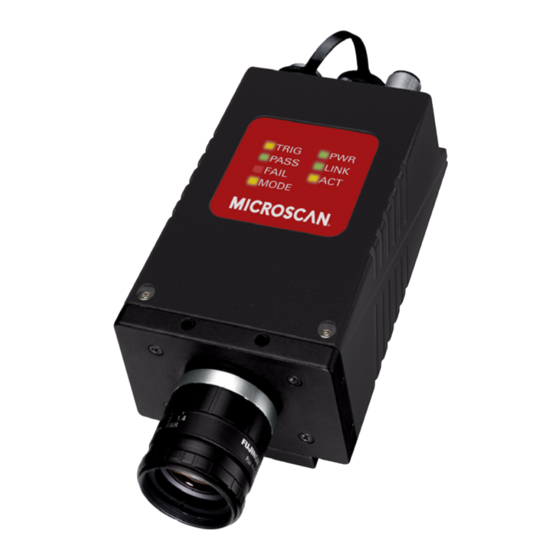
HawkEye™ 1600T Mode/Status LEDs Figure 2–3 shows the mode and status LEDs. Mode/Status LEDs FIGURE 2–3. Table 2–4 describes the mode and status LEDs. Mode/Status LEDs TABLE 2–4. Name Description LED Color TRIG Trigger LED Yellow PASS Pass LED Green FAIL Fail LED MODE... -
Page 28: Power-On Sequence
Chapter System Components • SN — The serial number of your HawkEye™ 1600T Smart Camera. • MAC ADDRESS — This unique address is important because, by default, a HawkEye™ 1600T Smart Camera’s name on the network is “HawkEyeXXXXXX,” where XXXXXX is the last six alphanumeric characters in its MAC address. -
Page 29: Mounting & Wiring The Hawkeye™ 1600T
HawkEye™ 1600T Mode/Status LED Power-On Sequence & Error Codes TABLE 2–5. (Continued) Mode Fail Pass Trig Test Performed • FPGA Video Buffer Test • • FPGA DMA Transfer Test • • FPGA Expose Done Interrupt Test • • • FPGA Read Done Interrupt Test Mounting &... -
Page 30: Mounting Using Standard Mounting Block
Chapter System Components Locations for Mounting Using Front Block FIGURE 2–4. M4 x .7 x 10 Caution: Using screws that are too long for the threaded holes may damage the HawkEye™ 1600T. The accessory mounting blocks use 10mm machine screws. Mounting Using Standard Mounting Block You can mount the HawkEye™... -
Page 31: Mounting Using Accessory Mounting Block
HawkEye™ 1600T Mounting Using Accessory Mounting Block You can mount the HawkEye™ 1600T using the accessory mounting block (see Figure 2–6). The backward compatible mounting block positions a HawkEye™ 1600T in the same position as a HawkEye™ 1600 for optical alignment. Accessory Mounting Blocks FIGURE 2–6. -
Page 32: Field I/O Wiring Examples
Chapter System Components Field I/O Wiring Examples Input Opto Wiring Figure 2–8 shows the input opto wiring for isolated NPN and PNP sources. Trigger Input Opto Wiring (NPN and PNP) FIGURE 2–8. NPN Sink PNP Source Camera Camera 15-30V IN A (or IN B) 15-30V Signal IN B (or IN A) -
Page 33: Output Opto Wiring
Field I/O Wiring Examples Output Opto Wiring Figure 2–10 shows the output opto wiring for isolated input. GPIO Output Opto Wiring (NPN and PNP) FIGURE 2–10. Camera NPN Sink Camera PNP Source See Note 2 GPIO OUT COM 15-30V GPIO IN COM 15-30V GPIO x Signal... - Page 34 Chapter System Components Figure 2–12 shows the output opto wiring for non-isolated inputs. GPIO Output Opto Wiring (Relay and PLC Inputs) FIGURE 2–12. GPIO OUT COM GPIO OUT COM 15-30V 15-30V GPIO x GPIO x Input See Note See Note GPIO IN COM GPIO IN COM GPIO IN COM typically connected to ground.
- Page 35 Field I/O Wiring Examples HawkEye™ 1600T I/O Simplified Circuit Diagram FIGURE 2–13. opto input IN A Rin=18 Kohm±5% IN B opto output OUT 1 Ron=24 ohm typ. 35 ohm max. OUT 2 OUT 3 OUT COM GPIO OUT COM opto output GPIO 1 GPIO 2 GPIO 3...
-
Page 36: External Strobe & Sensor
Chapter System Components External Strobe & Sensor For continuous motion or high-speed indexing applications, an external strobe and sensor may be required to freeze each part before the image can be acquired. When choosing your part sensor, you must consider the time interval between the part passing into the sensing zone and an electrical signal being generated. -
Page 37: Optics & Lighting
Optics & Lighting CHAPTER 3 This chapter contains information specific to the Optics and Lighting options for the HawkEye™ 1600T Smart Camera. HawkEye™ 1610T Smart Camera FIGURE 3–1. Rev. 1G, Dec 2008 HawkEye™ 1600T Smart Camera Guide... -
Page 38: Optics (1610T Only)
Chapter Optics & Lighting Optics (1610T Only) The HawkEye™ 1610T uses C-Mount lenses. Table 3–1 contains lens sizes and Microscan part numbers. Lens Sizes and Microscan Part Numbers TABLE 3–1. Part Number Size 98-92800571 Lens: 8mm 98-92800572 Lens: 12mm 98-92800573... -
Page 39: Lighting Connector
Lighting Connector Lighting Connector For complete information about the Light Port Connector, see “Light Port Connector” on page A-5. Rev. 1G, Dec 2008 HawkEye™ 1600T Smart Camera Guide... - Page 40 Chapter Optics & Lighting HawkEye™ 1600T Smart Camera Guide Rev. 1G, Dec 2008...
- Page 41 Connector Pinouts APPENDIX A This appendix contains information about the HawkEye™ 1600T connectors: • “Power & Primary I/O Connector” on page A-1 • “Serial & Secondary I/O Connector” on page A-3 • “Ethernet Connector” on page A-4 • “Light Port Connector” on page A-5 •...
-
Page 42: Connector Pinouts
Power & Primary I/O Connector Mating Cable TABLE A–1. Supplier Part Number Description Microscan 98-HT00-0CP0 Connector Type M12 8 Pin A Coded, Female Cable 10M Table A–2 describes the Power and Primary I/O connector signals. Power & Primary I/O Connector Signals TABLE A–2. -
Page 43: Serial & Secondary I/O Connector
Table A–3 lists the supplier for the Serial and Secondary I/O connector mating connector and cable. Serial & Secondary I/O Connector Mating Cable TABLE A–3. Supplier Part Number Description Microscan 98-HT00-0CS0 Connector Type M12 8 Pin A Coded, Male Cable 10M Rev. 1G, Dec 2008 HawkEye™ 1600T Smart Camera Guide... -
Page 44: Ethernet Connector
Appendix Connector Pinouts Table A–4 describes the Serial and Secondary I/O connector signals. Serial & Secondary I/O Connector Signals TABLE A–4. Signal Name Direction H/W Description Notes GPIO 3 In/Out S/W Programmable General Purpose I/O GPIO 4 In/Out S/W Programmable General Purpose I/O RS-232 Transmit RS-232 Receive GPIO 1... -
Page 45: Light Port Connector
Table A–5 lists the supplier for the Ethernet connector mating connector and cable. Ethernet Connector Mating Cable TABLE A–5. Supplier Part Number Description Microscan 98-HT00-0CE0 Connector Type M12 4 Pin D-Coded, Male Cable 10M (Unshielded) 98-HT00-0CE2 Connector Type M12 4 Pin D-Coded, Male Cable 2M (Unshielded) Table A–6 describes the Ethernet connector signals. - Page 46 Table A–7 lists the supplier for the Light Port connector and cable. Light Port Connector Mating Cable TABLE A–7. Supplier Part Number Description Microscan 98-HT00-0CL5 Connector Type M5 4 Pin, Male Cable 5M Table A–8 describes the Light Port connector signals. Light Port Connector Signals TABLE A–8.
-
Page 47: Quickset® Switch
HawkEyeTM 1600T Connectors QuickSet® Switch Note: On earlier production units only. The QuicSet function is not used on the HawkEye 1600T. Figure A–5 shows the location of the QuicSet switch and access screw. QuicSet® Switch & Access Screw “S1” – Rear View FIGURE A–5. - Page 48 Appendix Connector Pinouts HawkEye™ 1600T Smart Camera Guide Rev. 1G, Dec 2008...
-
Page 49: Cable Specifications
Cable Specifications APPENDIX B This appendix contains information about the HawkEye™ 1600T cables. Note: Cable specifications are published for information only. We do not guarantee the performance or quality of cables provided by other suppliers. Cable Part Numbers & Descriptions TABLE B–1. -
Page 50: Hetac-100 - Serial & Secondary I/O Cable
Appendix Cable Specifications Power & Primary I/O Cable FIGURE B–1. W h i t e O p t o 1 O u t B r o w n O p t o 2 O u t C o n n e c t o r : G r e e n O p t o 3 O u t M 1 2 x 8 P i n A C o d e d ( F ) - Page 51 HETAC-100 - Serial & Secondary I/O Cable Table B–3 describes the signals for the HETAC-100 Serial and Secondary I/O cable. HETAC-100 Serial & Secondary I/O Cable Signals TABLE B–3. M12 Pin Signal Name Wire Color Description GPIO 3 White General Purpose I/O 3 GPIO 4 Brown General Purpose I/O 4...
-
Page 52: Hetenet-Xxx - Ethernet Cable
Appendix Cable Specifications HETENET-XXX - Ethernet Cable The Ethernet cable has an M12 x 4 Pin D Coded male connector on one end, and a male RJ-45 connector on the other end. Figure B–4 shows the HETENET-XXX Ethernet cable. HETENET-XXX Ethernet Cable FIGURE B–4. - Page 53 HETLC-050 - Lighting Control Cable HETLC-050 Lighting Control Cable FIGURE B–5. C o n n e c t o r : B r o w n L i g h t O u t M 5 x 4 P i n C o d e d ( M ) W h i t e L i g h t R t n...
- Page 54 Appendix Cable Specifications HawkEye™ 1600T Smart Camera Guide Rev. 1G, Dec 2008...
-
Page 55: Specifications
Specifications APPENDIX C This appendix contains specifications and dimensions for the HawkEye™ 1600T camera and its mounting blocks. Specifications TABLE C–1. HawkEyeTM 1600TS HawkEyeTM 1610TH HawkEyeTM 1610TIS HawkEyeTM 1610TIH Height 45.50mm (1.791") Width 65.00mm (2.559") Depth 128.40mm (5.055") Weight 0.82kg (1.85 lbs) Power 20.4 to 28.8 volts 24 volts @ 250ma Nominal (not including external lighting) - Page 56 Appendix Specifications Specifications (Continued) TABLE C–1. HawkEyeTM 1600TS HawkEyeTM 1610TH HawkEyeTM 1610TIS HawkEyeTM 1610TIH Sensor 1/3 Inch CCD Cell Size 7.4µm (H) x 7.4µm (V) 4.65µm (H) x 4.65µm (V) Image Resolution 648 x 494 pixels, 256 grey levels (8 1024 x 768 pixels, 256 grey levels (8 bits per pixel) bits per pixel)
-
Page 57: Dimensions
Dimensions Dimensions HawkEye™ 1610T Dimensions FIGURE C–1. Rev. 1G, Dec 2008 HawkEye™ 1600T Smart Camera Guide... - Page 58 Appendix Specifications HawkEye™ 1610T Lens Protector Dimensions FIGURE C–2. Lens Protector Part Numbers & Descriptions TABLE C–2. Catalog # Part # Descriptions 98-HT00-0TA1 Lens Protection Housing with Glass screen. IP65 Rated 98-HT00-0TA2 HELTA-050 Lens Protection Housing with Plexiglas screen. IP65 Rated 98-HT00-0TA0 A1-40366-1 Lens Protection Adapter...
- Page 59 Dimensions Standard Mounting Block Dimensions FIGURE C–3. Backward Compatible Mounting Block Dimensions FIGURE C–4. Rev. 1G, Dec 2008 HawkEye™ 1600T Smart Camera Guide...
- Page 60 Appendix Specifications Spectral Sensitivity Characteristics (VGA) FIGURE C–5. Note: Excludes lens characteristics and light source characteristics. HawkEye™ 1600T Smart Camera Guide Rev. 1G, Dec 2008...
- Page 61 Dimensions Spectral Sensitivity Characteristics (XGA) FIGURE C–6. Note: Excludes lens characteristics and light source characteristics. Rev. 1G, Dec 2008 HawkEye™ 1600T Smart Camera Guide...
- Page 62 Appendix Specifications HawkEye™ 1600T Smart Camera Guide Rev. 1G, Dec 2008...
-
Page 63: Setting Up Network Communications
Setting Up Network APPENDIX D Communications By default, the HawkEye™ 1600T utilizes Dynamic Host Configuration Protocol (RFC2131) for dynamic IP addressing. You can also configure the camera to use a “static” IP address. Please contact your MIS department to determine if your network uses DHCP addressing. If your network uses static IP addressing, contact your MIS department to obtain a unique static IP address for the camera before proceeding. - Page 64 Appendix Setting Up Network Communications Select DHCP (“Obtain an IP address automatically”) or Static IP (“Use the following address”) and fill in a logical address and network mask, as shown in Figure D–1. Also, see Table D–1. Network Overview & Network Settings FIGURE D–1.
-
Page 65: Hawkeye™ 1600T Connection Matrix
HawkEye™ 1600T Connection Matrix When you are done, click OK. The camera will be rebooted automatically for the changes to take effect. Note: All the Network parameters of the camera are stored in Non-Volatile memory and can also be modified from the Bootloader (a low-level diagnostics program) that can be invoked using HyperTerminal and a Serial connection. -
Page 66: Hawkeye™ Boot Parameters
Appendix Setting Up Network Communications To check a camera IP address, simply select the camera in FrontRunner Network Overview. To check a host PC IP address1: At the DOS prompt, type: ipconfig HawkEye™ Boot Parameters The HawkEye™ 1600T Smart Camera stores network and other parameters in Non-Volatile memory. - Page 67 HawkEye™ Boot Parameters For each parameter that is displayed, simply type in new information (to change the parameter), or press the Return key to display the next parameter. Eventually, you’ll see the message “Save parameters to flash? [y/n] - Type y and press the Return key. You’re finished changing network parameters.
- Page 68 Appendix Setting Up Network Communications HawkEye™ 1600T Smart Camera Guide Rev. 1G, Dec 2008...
-
Page 69: Updating Firmware On 1600T Cameras
Updating Firmware on 1600T APPENDIX E Cameras This appendix contains two procedures for updating your Smart Camera: • “Updating the Firmware with Smart Camera Update” on page E-1 • “Updating the Firmware with the Bootloader” on page E-3 Updating the Firmware with Smart Camera Update Note: Do not cycle power on the Smart Camera during this procedure. - Page 70 Appendix Updating Firmware on 1600T Cameras Smart Camera Update Main Screen FIGURE E–1. Select Camera Select Firmware Version In the top pull-down menu, select the Smart Camera you want to update. In the bottom pull-down menu, select the desired firmware version. Enter the user name (default is hawkeye) and password (default is vision) for the Smart Camera Click Update Firmware.
-
Page 71: Updating The Firmware With The Bootloader
Updating the Firmware with the Bootloader Updating the Firmware with the Bootloader If power is lost while the Smart Camera Update is in progress, the Smart Camera will not boot when power is restored. When this occurs, you will need to use the Bootloader application in Non-Volatile memory (which is not erased by the Smart Camera Update utility) to update the firmware. - Page 72 Appendix Updating Firmware on 1600T Cameras Network Mask: 255.255.255.0 Gateway: 0.0.0.0 DHCP: 0 MAC Address: 00:60:33:e1:12:34 1. Modify User Parameters 2. Reset User Account 3. Exit to Application >> Type adv and press the Enter key. The advanced menu is displayed: Advanced Options Menu Diag Monitor V 1.01.00 ------------------------------...
- Page 73 Updating the Firmware with the Bootloader Send File Dialog Box FIGURE E–3. Click Browse, and navigate to C:\Vscape\370_xx\AcuitySmartCam. Highlight filename.SEC. Click Open. In the Protocol: drop-down menu, select Xmodem. After you click Open, your screen should look similar to one in Figure E–4: Send File Dialog Box After Filename &...
- Page 74 Appendix Updating Firmware on 1600T Cameras Xmodem File Send in Progress FIGURE E–5. When the file transfer terminates, you will see a screen similar to the one displayed in Figure E–6. HawkEye™ 1600T Smart Camera Guide Rev. 1G, Dec 2008...
-
Page 75: Main Menu Items
Main Menu Items Xmodem File Send in Progress FIGURE E–6. Type q and press the Enter key to exit the advanced menu and return to the main menu. Type 3 and press the Enter key to exit the main menu. You’re finished. -
Page 76: Reset User Account
Appendix Updating Firmware on 1600T Cameras Use DHCP: 0 - 1 Save parameters to flash? [y/n] - y Saving boot parameters to flash……done. Network Name — This is limited to 19 characters. Any input string longer • than 19 characters is truncated automatically to the first 19 characters. The string is erased by entering the '.' (period) character. -
Page 77: Error Codes
Error Codes Error Codes When the Smart Camera fails to boot (i.e., self tests fail), the LEDs on the front of the unit flash the error code in binary form. Table E–1 describes the Mode/Status LED power-on sequence and error codes. Mode/Status LED Power-On Sequence &... - Page 78 Appendix Updating Firmware on 1600T Cameras E-10 HawkEye™ 1600T Smart Camera Guide Rev. 1G, Dec 2008...
- Page 79 Index Non-Volatile Memory job storage in Output Opto Wiring 2-13 Additional Power Supply flash wiring 2-16 system memory QuicSet Cable Specifications sealing screw how tight? A-7 Firmware updating Rear Panel Layout Flash additional Sealing Screw quicset HawkEye 1610 Front Panel Layout how tight? A-7 Smart Camera Input Opto Wiring...
Need help?
Do you have a question about the HawkEye 1600T and is the answer not in the manual?
Questions and answers