Table of Contents
Advertisement
Quick Links
Weighing systems
Electronic weighing system
SIWAREX WT241
Manual
05/2015
A5E36046748A
Introduction
Safety guidelines
Description
Application planning
Installation
Connecting
Commissioning
Scale parameters and
functions of the belt scale
Messages
Command lists
Communication
Technical specifications
Accessories
ESD guidelines
List of abbreviations
1
2
3
4
5
6
7
8
9
10
11
12
13
B
C
Advertisement
Table of Contents

Related Manuals for Siemens SIWAREX WT241


Summary of Contents for Siemens SIWAREX WT241
- Page 1 Introduction Safety guidelines Description Weighing systems Application planning Electronic weighing system SIWAREX WT241 Installation Connecting Manual Commissioning Scale parameters and functions of the belt scale Messages Command lists Communication Technical specifications Accessories ESD guidelines List of abbreviations 05/2015 A5E36046748A...
- Page 2 Note the following: WARNING Siemens products may only be used for the applications described in the catalog and in the relevant technical documentation. If products and components from other manufacturers are used, these must be recommended or approved by Siemens. Proper transport, storage, installation, assembly, commissioning, operation and maintenance are required to ensure that the products operate safely and without any problems.
-
Page 3: Table Of Contents
Safety notes ............................13 General safety instructions ..................... 13 Description ............................15 Product overview ........................15 Area of application ........................15 SIWAREX WT241 product overview ..................16 Customer benefits ........................17 Scope of delivery ........................17 Application planning ..........................19 Functions ..........................19 Installation ............................ - Page 4 Commissioning without speed sensor ................... 47 7.3.3 Determination of a correction factor ..................57 Scale parameters and functions of the belt scale ................... 59 SIWAREX WT241 Operating View ..................59 8.1.1 Dynamic status in operating view ..................60 Menu tree ..........................62 Menu 1.1 Basic parameters ....................
- Page 5 Automatic span calibration with load cell data ..............112 11.6.4 Span calibration by test chain ....................113 11.6.5 Span calibration with known material flow ................113 11.7 DR 4 Temporary parameters ....................115 11.7.1 Stop watch ..........................117 11.7.2 Result calculator ........................117 SIWAREX WT241 Manual, 05/2015, A5E36046748A...
- Page 6 DR 12 Ethernet parameters ....................137 11.14.1 Device MAC address ......................138 11.14.2 Port MAC address ........................ 138 11.14.3 IP address ..........................138 11.14.4 Subnet mask ........................138 11.14.5 Gateway ..........................139 11.14.6 Device name ........................139 SIWAREX WT241 Manual, 05/2015, A5E36046748A...
- Page 7 Data and operator errors, bytes 0 to 7 .................. 163 11.25.2 Modbus RTU error code ....................... 163 11.25.3 Modbus Ethernet error code ....................163 11.25.4 SIWATOOL error code......................163 11.25.5 Error code following commands at digital input ..............163 SIWAREX WT241 Manual, 05/2015, A5E36046748A...
- Page 8 DR 48 Date and time 2 ......................170 Technical specifications ........................171 12.1 Technical specifications ....................... 171 12.2 Electrical, EMC and climatic requirements ................176 12.3 Approvals ..........................179 Accessories ............................181 ESD Guidelines ........................183 List of abbreviations ......................185 SIWAREX WT241 Manual, 05/2015, A5E36046748A...
-
Page 9: Introduction
Purpose of the manual This manual contains all necessary information on the setup, installation, wiring and commissioning of the SIWAREX WT241 electronic weighing system. Basic knowledge required This manual requires basic knowledge of weighing technology and of belt scales specifically. -
Page 10: Technical Support
● Information about field service, repairs, spare parts and lots more under "Services". Additional Support Please contact your local Siemens representative and offices if you have any questions about the products described in this manual and do not find the right answers. - Page 11 Introduction 1.4 Technical support See also E-mail (mailto:support.automation@siemens.com) SIWAREX WT241 Manual, 05/2015, A5E36046748A...
-
Page 13: Safety Notes
WARNING Commissioning is absolutely prohibited until it has been ensured that the machine in which the component described here is to be installed fulfills the regulations/specifications of Machinery Directive 89/392/EEC. SIWAREX WT241 Manual, 05/2015, A5E36046748A... - Page 14 The device does usually not pose any risks of material damage or personal injury. Siemens provides automation and drive products with industrial security functions that support the secure operation of plants or machines. They are an important component in a holistic industrial security concept.
-
Page 15: Description
Description Product overview SIWAREX WT241 is a versatile and flexible weighing module that can be operated as a belt scale. The electronic weighing system uses all features of a modern automation system, such as integrated communication, operation and monitoring, the diagnostic system and an up to date user interface. -
Page 16: Siwarex Wt241 Product Overview
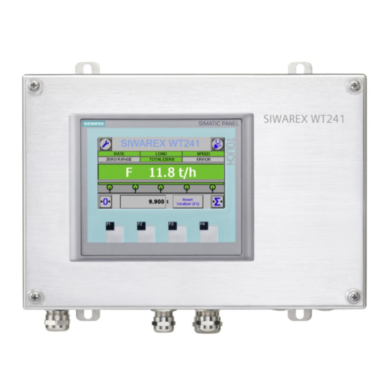
Description 3.3 SIWAREX WT241 product overview SIWAREX WT241 product overview The electronic weighing system described here is a stand-alone weighing electronic; having all functions and interfaces on board, which are necessary to operate an industrial scale. Figure 3-1 SIWAREX WT241 weighing terminal... -
Page 17: Customer Benefits
● Exact determination of speed – with or without encoder ● Diagnostics functions Scope of delivery The scope of delivery is as follows: Weighing terminal SIWAREX WT231 Pre-mounted wall fastening M20 to M16 reduction ring M16 cable SIWAREX WT241 Manual, 05/2015, A5E36046748A... -
Page 19: Application Planning
Further the SIWAREX WT241 can be connected to any control system or to a PC by using the Modbus RTU protocol. -
Page 20: Installation
Installation Installation guideline The weighing electronic SIWAREX WT241 is equipped with 4 lugs on the backside of the product. These can be used for fastening the device at a wall. Please consider material and condition of the wall, when choosing the mounting equipment. -
Page 21: Emc-Compliant Setup
● Electrical coupling ● Capacitive coupling ● Inductive coupling ● Radiation coupling 5.2.4 Five basic rules for securing EMC Observe these five basic rules to secure EMC. SIWAREX WT241 Manual, 05/2015, A5E36046748A... - Page 22 ● Create a homogeneous reference potential and ground all electrical equipment. ● Use sufficiently dimensioned equipotential bonding conductors if potential differences exist or are expected between your system components. Equipotential bonding is absolutely mandatory for applications in hazardous areas. SIWAREX WT241 Manual, 05/2015, A5E36046748A...
-
Page 23: Connecting
Switch off the machine so that it is in a no-voltage condition before you open the terminal box. Overview The weighing terminal SIWAREX WT241 comes with a number of connection options. It is equipped with EMC safe cable glands for the major connections (mains and load cells). - Page 24 Connecting 6.1 Overview Connections at bottom side Figure 6-2 SIWAREX WT241 bottom side with connections ① M16 cable gland for mains cable ② Earthing bolt ③ M16 and M20 cable glands for load cells ④ Through holes equipped with dummy plugs...
- Page 25 Terminal board to connect load cells / belt scale, analog output, speed sensor ③ Connections to SIWAREX WP241 – premounted to ④ ④ ③ Upper terminal block SIWAREX WP241 – premounted to ⑤ Lower terminal block SIWAREX WP241 – Digital inputs, digital outputs, RS485 SIWAREX WT241 Manual, 05/2015, A5E36046748A...
-
Page 26: Connecting To Main Voltage
Cable gland M16 x 1.5: clamping range 6…10 mm Cable gland M20 x 1.5: clamping range 10…14 mm Note Minimum wire range Use connector cable with a minimum wire range of 0.75 mm². SIWAREX WT241 Manual, 05/2015, A5E36046748A... - Page 27 Marking Type Function Input Clamp for 100 ~ 240 VAC; 50 / 60Hz – L Input Clamp for neutral wire Input Clamp for PE Output 24V ground Output +24V Figure 6-4 SIWAREX WT241 power supply SIWAREX WT241 Manual, 05/2015, A5E36046748A...
-
Page 28: Connecting The Load Cells
6.3 Connecting the load cells Connecting the load cells Overview Pickups can be connected to the SIWAREX WT241 electronic weighing system which are equipped with strain gauges (full bridge) and meet the following requirements. ● Characteristic value 1 to 4 mV/V ●... - Page 29 The signals will be paralleled due to the layout of the PCB. Use a well- shielded cable for the connection between belt scale and SIWAREX WT241. 2. The cable shield is always applied at the cable gland of the junction box (SIWAREX JB).
-
Page 30: Connection Of An Mlc / Mbs / Mus / Mcs / Msi / Mmi Belt Scale To Wp241
Connection of an MLC / MBS / MUS / MCS / MSI / MMI belt scale to WP241 The following graphic clarifies the interfacing of all Siemens belt scale types to SIWAREX WP241. When using several MSI scales (MMI2 or MMI3) installed in sequence, all additional load cells are connected in parallel in the junction box as shown in the graphic. - Page 31 Connecting 6.3 Connecting the load cells Figure 6-7 Connecting a Siemens beltscale MMI-2 to SIWAREX WT241 SIWAREX WT241 Manual, 05/2015, A5E36046748A...
-
Page 32: Connection Of Any Scales Or Load Cells
6.3.2 Connection of any scales or load cells Connecting any other beltscale or load cells to the SIWAREX WT241 is done by using the terminal board within the device. Thereon 4 terminal blocks are mounted, each for connecting one load cell to it. - Page 33 Connect strain gauge load cells with 6 wires Figure 6-9 Connection of strain gauge load cell(s) with 6-wire system ① Load cell ② Load cell shield ③ Cable glands shield connection ④ SIWAREX WT2X1 weighing terminal ⑤ Earthing bolt SIWAREX WT241 Manual, 05/2015, A5E36046748A...
- Page 34 Bridge wires 2. Add wire bridges between the pins EXC- and SEN- as well between EXC+ and SEN+. The electronic will report a load cell error in case the bridge wires have not been set. SIWAREX WT241 Manual, 05/2015, A5E36046748A...
-
Page 35: Shield Connection
Use only cables with protective braided shield (see recommended cables of load cells in chapter Accessories (Page 181)). Shielding density must be at least 80%. The SIWAREX WT241 is equipped with EMC safe cable glands. Follow the instruction below for proper connected shield. -
Page 36: Connection Of Digital Outputs (4 X Dq)
Labeling Function DQ.0 Digital output 0 DQ.1 Digital output 1 DQ.2 Digital output 2 DQ.3 Digital output 3 DQ.3L+ +24 V DC power supply for digital outputs DQ.3M Ground of power supply for digital outputs SIWAREX WT241 Manual, 05/2015, A5E36046748A... -
Page 37: Connection Of Digital Inputs (4 X Di)
Connection of the digital inputs Labeling Function DI.0 Digital input 0 (input for speed sensor) DI.1 Digital input 1 DI.2 Digital input 2 DI.3 Digital input 3 DI.2M Reference ground potential of the digital inputs SIWAREX WT241 Manual, 05/2015, A5E36046748A... -
Page 38: Connection Of The Analog Output (1 X Aq)
RS485 data line - for feeding in of bus signal If a SIWAREX WP241 module forms the termination of an RS485 network, insert wire jumpers between the D+‘ and T+ terminals and between the D-‘ and T- terminals for termination of the bus network SIWAREX WT241 Manual, 05/2015, A5E36046748A... -
Page 39: Connection Of A Speed Sensor
The DI.0 can be found on the PCB board in the connection area ④. Connection of the various Siemens speed sensors is shown below. A wide range of pulse sensors can be used up to a clock frequency of 5 000 Hz. A level of at least +15 V DC is required for the High signal. -
Page 40: Tass Speed Sensor On Wt241
Connecting 6.9 Connection of a speed sensor 6.9.2 TASS speed sensor on WT241 Figure 6-12 TASS speed sensor on WT241 SIWAREX WT241 Manual, 05/2015, A5E36046748A... -
Page 41: Ws300 Speed Sensor On Wt241
Connecting 6.9 Connection of a speed sensor 6.9.3 WS300 speed sensor on WT241 Figure 6-13 WS300 speed sensor on WT241 SIWAREX WT241 Manual, 05/2015, A5E36046748A... -
Page 43: Commissioning
Factory-set parameters The electronic weighing system described here is provided with factory-set parameters. Parameters which can be entered in % or time are preset in such a way that they provide good results for most applications. SIWAREX WT241 Manual, 05/2015, A5E36046748A... -
Page 44: Commissioning Via Quick Start Routine
7.3 Commissioning via Quick Start routine Commissioning via Quick Start routine The SIWAREX WT241 offers a setup menu to carry out the commissioning of the scale. Select item "1.0 Setup" in the main menu. The system is guiding you through the most important parameters for starting-up the scale. - Page 45 When using a speed sensor, use the standard setting "Speed sensor on digital input DI.0" in the speed detection parameter. Enter the remaining parameters appropriate to your application, and confirm them using the save button. Further information on the individual parameters can be found in chapter → SIWAREX WT241 Manual, 05/2015, A5E36046748A...
- Page 46 = diameter of guide pulley in meters The inputs are completed using the save button (diskette symbol). Then move on to the "Zero calibration" using → Zero calibration (Page 52). Figure 7-4 Specification of pulse constant SIWAREX WT241 Manual, 05/2015, A5E36046748A...
-
Page 47: Commissioning Without Speed Sensor
Then move on to the "Zero calibration" using → Zero calibration (Page 52). 7.3.2 Commissioning without speed sensor You can define a known, constant speed or calculate the current belt speed. In addition, a speed can be defined externally using data record 19. SIWAREX WT241 Manual, 05/2015, A5E36046748A... - Page 48 ● From the operator panel (menu 1.4.5) You can reset the speed to zero again using the "Reset "Belt is running"" command. Then move on to the "Zero calibration" using → Zero calibration (Page 52). SIWAREX WT241 Manual, 05/2015, A5E36046748A...
- Page 49 Determination of current belt speed (belt loaded) In addition to the speed calculation with empty belt, a further calculation can be carried out with the belt loaded. In this case the characteristic of the motor with load is recorded. SIWAREX WT241 Manual, 05/2015, A5E36046748A...
- Page 50 Prerequisites for determination of the characteristic are: ● Speed calculation has been carried out with empty belt ● Successful zero calibration ● Successful span calibration If these conditions have been fulfilled, move on to menu item 1.2.1.3. SIWAREX WT241 Manual, 05/2015, A5E36046748A...
- Page 51 0 into data record 19 and send this to the electronics. Following a power loss, a value of 0 is used automatically, and you must again send the current speed externally. SIWAREX WT241 Manual, 05/2015, A5E36046748A...
- Page 52 (Page 52). 7.3.2.6 Span calibration There are four options for the span calibration: ● Using test weights ● Using a test chain ● Using a material batch ● Automatically using entered load cell data SIWAREX WT241 Manual, 05/2015, A5E36046748A...
- Page 53 You can improve the results for your system even further following completion of the calibration or also during subsequent operation by means of a flow correction by material test ( → Determination of a correction factor (Page 57)). SIWAREX WT241 Manual, 05/2015, A5E36046748A...
- Page 54 Further information on these and all other parameters can be found in chapter → Scale parameters and functions of the belt scale (Page 59). You can return to the main screen using the "Home" button (house symbol). SIWAREX WT241 Manual, 05/2015, A5E36046748A...
- Page 55 5. Start the required calculations using the "Calculate new span digits" button. The calculated calibration weight and the calculated span digits are displayed. 6. Import the values using "Apply new span digits". Commissioning has then been completed. SIWAREX WT241 Manual, 05/2015, A5E36046748A...
- Page 56 1.0 mV/V, 2.0 mV, 3.0 mV/V or 4.0 mV/V. 3. Select the interfering frequency suppression. The interfering frequency suppression is used to effectively filter out interferences from the power supply network (50 Hz/60 Hz). SIWAREX WT241 Manual, 05/2015, A5E36046748A...
-
Page 57: Determination Of A Correction Factor
Navigate in the menu to item "1.2.4 Flow correction by material test". Figure 7-15 Flow correction by material test 1. Make sure that the belt is running and empty. 2. Start the material test using the "Start material test (reset totalizer 6)" button. SIWAREX WT241 Manual, 05/2015, A5E36046748A... - Page 58 You can use several correction factors for different belt loads by using the SIWATOOL service and commissioning tool. It is then possible to determine an additional correction factor for a further, higher belt load. A correction characteristic is then produced depending on the belt load. SIWAREX WT241 Manual, 05/2015, A5E36046748A...
-
Page 59: Scale Parameters And Functions Of The Belt Scale
Scale parameters and functions of the belt scale SIWAREX WT241 Operating View Figure 8-1 Operating View SIWAREX WT241 Variable Description Variable Description Go to main menu RATE Limit flow rate Yellow if current rate below min- imum limit Red if current rate above maxi- mum limit Setting in „1.3.1 Limits 1/2“... -
Page 60: Dynamic Status In Operating View
Scale parameters and functions of the belt scale 8.1 SIWAREX WT241 Operating View 8.1.1 Dynamic status in operating view The operating view supports you with dynamic, visualized status information regarding flow rate, belt load and belt speed. Scale is working within it’s settings Flow rate is above maximum limit (see menu “1.3.1 Limits 1 / 2”) - Page 61 Scale parameters and functions of the belt scale 8.1 SIWAREX WT241 Operating View Belt speed is above maximum limit (see menu “1.3.1 Limits 1 / 2”) Belt speed is below minimum limit (see menu “1.3.1 Limits 1 / 2”) Belt load is above maximum limit (see menu “1.3.1 Limits 1 / 2”)
-
Page 62: Menu Tree
Scale parameters and functions of the belt scale 8.1 SIWAREX WT241 Operating View Menu tree 1.0 Setup 1.1 Basic parameters page 63 1.2 Calibration page 65 1.3 Limits page 65 1.4 Additional parameters page 66 1.5 Communication & interfaces page 68 1.6 Recovery / Reset... -
Page 63: Menu 1.1 Basic Parameters
With two or more roller stations, the distance between the roller stations is added to this. SIWAREX WT241 Manual, 05/2015, A5E36046748A... - Page 64 2. Speed simulation 3. Load and speed simulation Without enabling one of these modes within the basic parameters, a simulation cannot be started. In case one simulation mode is chosen, the menu “1.5.9 Simulation” will get accessable. SIWAREX WT241 Manual, 05/2015, A5E36046748A...
-
Page 65: Menu 1.2 Calibration
The specification is made in % of the nominal belt load which was determined during commissioning. Violation of the limits for the belt load is delayed by the specified time. The specification is made in ms. SIWAREX WT241 Manual, 05/2015, A5E36046748A... -
Page 66: Menu 1.4 Additional Parameters
The input is unnecessary if the inclination is always constant: the influence of the constant angle is compensated or automatically taken into considera- tion during the calibration with weights or test chain. SIWAREX WT241 Manual, 05/2015, A5E36046748A... - Page 67 The number of the filter defines the effect of damping. The values 2, 4, load“ low pass filter 6, 8, and 10 can be set. The higher the selected order number, the higher the damping effect of the filter. SIWAREX WT241 Manual, 05/2015, A5E36046748A...
-
Page 68: Menu 1.5 Communication & Interfaces
6,4 ms – 12,8 ms Output DQ.0 … A status display can be assigned to a digital input. This is done on the DQ.3 basis of chosing the status out of the drop down menu. SIWAREX WT241 Manual, 05/2015, A5E36046748A... - Page 69 Defined value -- The relevant substitute value is activated – All „TRUE“ -- Outputs are switched on 1.5.2 Analogue output SIWAREX WT241 is providing one analogue output which is parameterized in menu 1.5.2. Range This parameter is used to define the output current range.
- Page 70 1.5.6 Trace settings The trace function allows recording virtually all process values, limit values, in- and outputs of the SIWAREX WT241. Trace rate The trace function is used for the continuous recording of measured val- ues. The recording rate is defined with the parameter.
- Page 71 2” the menus 1.5.9.1 Load simulation and / or 1.5.9.2 Speed simulation will be shown. 1.5.9.1 Load simulation Belt load simulati- Enter the belt load value to be simulated. on value Start load simula- Start simulation tion Stop load simula- Stop simulation SIWAREX WT241 Manual, 05/2015, A5E36046748A...
-
Page 72: Menu 1.6 Recovery / Reset
- all parameters and saved data (including protocol memory and logbook) as well as the restore point are loaded with the default values - all message buffers (diagnostics buffer, trace memory, etc.) are reset Menu 2.1 Messages Opens the message log of the weighing electronic. SIWAREX WT241 Manual, 05/2015, A5E36046748A... -
Page 73: Menu 2.2 Scale Status
You can directly jump into menu 2.2.1 by pressing the belt scale within the operating view. Figure 8-3 SIWAREX WT241 operating view – press the belt scale to jump to menu 2.2.1 2.2.1 Scale status1 of 5 This overview shows the main process values of the beltscale. - Page 74 Set in case minimum belt load for totalizing is not underrun – > Min. belt load for totaliz- this is a condition for totalizing 2.2.4 Scale status 4 of 5 Further process values Speed simulation active Set in case simulation mode speed is active SIWAREX WT241 Manual, 05/2015, A5E36046748A...
- Page 75 No. of zero calibrations Number of performed zero calibrations. Will be reset with restor- ing the default values. No. of span calibrations Number of performed span calibrations. Will be reset with restor- ing the default values. SIWAREX WT241 Manual, 05/2015, A5E36046748A...
-
Page 76: Menu 2.3 Flow Trend
8.12 Menu 2.4 Module information 2.4.1 Modul information General information about the SIWAREX WT241 Order number Order number of the weighing module used in the terminal. Serial number Serial number of the weighing module used in the terminal. -
Page 77: Menu 2.5 Start & Stop Trace
Totalizer S6 will stay active even with setting the order to stop disable totalizers. Therefore e.g. material tests or a calibration of the scale can be done without booking the “conveyed material” (calibration weights, test chain, etc.). SIWAREX WT241 Manual, 05/2015, A5E36046748A... - Page 78 Totalizer S6 will work independently. Disable totalizers (F3) Deactivates all totalizers. Totalizer S6 will continue to sum. Minimum belt load for total- Is green as long as the minimum belt load for totalizing is given or exceeded. izing SIWAREX WT241 Manual, 05/2015, A5E36046748A...
-
Page 79: Menu 5.0 User Management
8.16 Menu 5.0 User management 8.16 Menu 5.0 User management The SIWAREX WT241 provides password protection. It is activated by default. The password protection can be deactivated (and reactivated again) via a DIP switch at the weighing module SIWAREX WP241 inside the terminal. -
Page 80: Screen Saver
Choose “Control Panel” to call up the system settings of the touch panel. Under “Screensaver” the delay time can be adjusted as described above. In addition you can add acoustic feedback in menu “Sound Settings”. CAUTION Do not change any other settings! SIWAREX WT241 Manual, 05/2015, A5E36046748A... -
Page 81: Messages
Technology errors occur spontaneously due to the process flow of a weighing. Status bits, on the other hand, are not messages. The status displays describe the status of the scale during normal operation and can be monitored or evaluated at any time. SIWAREX WT241 Manual, 05/2015, A5E36046748A... -
Page 82: Message Paths
The following message paths are possible: ● Output of the message buffer to the SIWATOOL program (takes place automatically) ● Output by means of data records DR 30 and DR 32 in case of communication with a Modbus master SIWAREX WT241 Manual, 05/2015, A5E36046748A... -
Page 83: Message List
2003 The zeroing procedure has been canceled. Possible causes: violation of zeroing limits. 2004 Trace memory full 2004 The trace recording has been cancelled. Possible causes: trace memory full and not declared as ring memory. SIWAREX WT241 Manual, 05/2015, A5E36046748A... -
Page 84: Data And Operating Errors Message List
7002 Specifications of string lengths not 7002 The string header in a specified string variable is not plausi- plausible ble. 7003 Specification of date / time not plau- 7003 Specifications for date and time are not plausible. sible SIWAREX WT241 Manual, 05/2015, A5E36046748A... - Page 85 7020 Speed parameter or sensor parame- 7020 The speed parameter or sensor parameter in DR3 is not ter not plausible plausible. 7021 Units are not plausible 7021 The selected units are not plausible (mixing of metric and imperial parameters). SIWAREX WT241 Manual, 05/2015, A5E36046748A...
-
Page 87: Command Lists
→ Table 10-4 Commands 1000 ... : Basic functions for weighing commands (Page 91) → Table 10-5 Data record commands of SIWAREX WP241 (Page 91) → Table 10-6 Totalizing commands of SIWAREX WP241 (Page 91) See also Command lists (Page 88) SIWAREX WT241 Manual, 05/2015, A5E36046748A... -
Page 88: Command Lists
3. The span of the scale characteristic is determined for the parameter- ized number of belt revolutions. The result is initially entered in DR4 and can then be imported into DR3 using command 89. SIWAREX WT241 Manual, 05/2015, A5E36046748A... - Page 89 DR4. Apply (nominal) speed The nominal speed determined by the commands 70/71 is copied from DR4 to DR3. Apply speed parameters The result of the commands 72/73 is copied from DR4 to DR3. "belt loaded" SIWAREX WT241 Manual, 05/2015, A5E36046748A...
- Page 90 Total S6 Shows the current totalizer S6 Display calibration regula- Displays the entered calibration regulations tions Serial number Displays the serial number of the module Display SIWAREX FW Displays the firmware version of the module version SIWAREX WT241 Manual, 05/2015, A5E36046748A...
- Page 91 Reset totalizer S4 Resets totalizer 4 to 0 Reset totalizer S5 Resets totalizer S5 to 0 Reset totalizer S6 Resets totalizer S6 to 0 Reset totalizers S3...S6 Simultaneously resets totalizers S3 to S6 to 0 SIWAREX WT241 Manual, 05/2015, A5E36046748A...
-
Page 93: Communication
Each Modbus partner has its own address. The SIWAREX module has the default address 1. This address can be changed as a parameter (e.g. in SIWATOOL). This address is without significance if the Ethernet interface is used because the connection is based on the IP address. SIWAREX WT241 Manual, 05/2015, A5E36046748A... -
Page 94: Data Record Concept
(Page 59) describes the data records, variables and functions, including the register addresses. The data records are always checked as complete data packets for plausibility. For this reason, you must follow a specific procedure to change individual parameters. SIWAREX WT241 Manual, 05/2015, A5E36046748A... -
Page 95: Command Mailboxes
If you wish to read the registers from the data records DR 3 to DR 29, you must first export these as a complete data record to the internal output buffer. All Modbus registers of the individual parameters can be found in chapter → Scale parameters and functions of the belt scale (Page 59). SIWAREX WT241 Manual, 05/2015, A5E36046748Aa... -
Page 96: Writing Registers
(from the area of data/operator errors). You can find all further command numbers in chapter → Command lists (Page 87). In addition, an online document is available for working with SIWAREX WP231 and Modbus → Modbus communication of WP231 (http://support.automation.siemens.com/WW/view/de/77913998). SIWAREX WT241 Manual, 05/2015, A5E36046748A... -
Page 97: Parameters And Functions
When it receives new parameters, the SIWAREX module runs a validation check. In the event of a parameter assignment error, the complete data record is not applied (not saved) by the SIWAREX module and a data/operator error is reported. SIWAREX WT241 Manual, 05/2015, A5E36046748Aa... -
Page 98: Dr 2 Command Code
Contains no. of data rec- USHORT 1000 Length Data record length infor- USHORT 1001 mation Application Information about which USHORT 1002 application the DR be- longs to Version identifier Information about current USHORT 65635 1003 data record version SIWAREX WT241 Manual, 05/2015, A5E36046748A... - Page 99 FLOAT 1028 (Page 104) empty belt Speed correction if Only relevant if no sensor FLOAT 0.98 1030 belt loaded present. Percentage de- (Page 104) viation in speed when belt is loaded (see next pa- rameter) SIWAREX WT241 Manual, 05/2015, A5E36046748Aa...
- Page 100 TRUE for the specified time (minutes) Interface for the legal 0: HMI SecureDisplay at USHORT 1050 trade display ETHERNET (Page 107)(available 1: HMI SecureDisplay via soon) S7 interface HMI SecureDisplay string UBYTE[2] 1051 header version SIWAREX WT241 Manual, 05/2015, A5E36046748A...
-
Page 101: Scale Name
1 – verification in accordance with OIML R50 2 – verification in accordance with NTEP Book 44 (approvals available soon). Note If the jumper is closed to protect data with verification capability, the parameter can no longer be changed. SIWAREX WT241 Manual, 05/2015, A5E36046748Aa... -
Page 102: Unit For Belt Load
EN 45501 (1*10**k, 2*10**k, 5*10**k]; k: -3 … 2) from 0.0001 to 50. Note If the jumper is closed to protect data with verification capability, the parameter can no longer be changed. SIWAREX WT241 Manual, 05/2015, A5E36046748A... -
Page 103: Resolution Of Flow Rate
With two or more roller stations, the distance between the roller stations is added to this. Note If the jumper is closed to protect data with verification capability, the parameter can no longer be changed. SIWAREX WT241 Manual, 05/2015, A5E36046748Aa... -
Page 104: Belt Length
This characteristic is determined by two working points: Design speed with empty belt and a speed factor correction with a certain belt load factor. The specification is made in % of the design speed. SIWAREX WT241 Manual, 05/2015, A5E36046748A... -
Page 105: Belt Load Factor For Speed Correction
Note If the jumper is closed to protect data with verification capability, the parameter can no longer be changed. SIWAREX WT241 Manual, 05/2015, A5E36046748Aa... -
Page 106: Calibration Weight
DR16. You can enable test mode at any time using the commands "Load simulation ON" (3) or "Speed simulation ON" (5), or disable test mode using the commands "Load simulation OFF" (4) or "Speed simulation OFF" (6). SIWAREX WT241 Manual, 05/2015, A5E36046748A... -
Page 107: Warm-Up Timer
Minimum display size in % of the HMI SecureDisplay with verification capability This parameter is not yet effective since the function is in preparation. The smallest display size which can still be easily read is defined for representation of the display with verification capability. SIWAREX WT241 Manual, 05/2015, A5E36046748Aa... -
Page 108: Calibration Procedure
This is followed by calibration of the weight measurement – the span calibration. 11.5.2 Calibration of the speed Procedure in three steps Calibrate the speed using the following steps: SIWAREX WT241 Manual, 05/2015, A5E36046748A... - Page 109 "Trigger for belt revolution detection on DI" (75)) and use it to measure the belt revolution. The defined number of belt revolutions is recorded following enabling by the command "Enable belt revolution detection on DI (74)". SIWAREX WT241 Manual, 05/2015, A5E36046748Aa...
-
Page 110: Specification Of Known Speed Parameters
– DR3 → design speed = maximum speed of belt ● With an external speed input via DR19, you must enter the following parameters manually: – DR3 → design speed = maximum speed of belt SIWAREX WT241 Manual, 05/2015, A5E36046748A... -
Page 111: Calibration Of Weight Measurement
1. Stop the belt. 2. Enter a test weight appropriate to the measuring range in DR3 (e.g. 50% of the measuring range). 3. Attach this test weight to the scale or place it onto the scale. SIWAREX WT241 Manual, 05/2015, A5E36046748Aa... -
Page 112: Automatic Span Calibration With Load Cell Data
If the belt scale has not been installed exactly horizontally, enter the inclination angle of the belt in data record DR15 and send this to the scale. The characteristic curve has thus been determined. The scale can calculate the weight values for the complete measuring range. SIWAREX WT241 Manual, 05/2015, A5E36046748A... -
Page 113: Span Calibration By Test Chain
However, a known quantity of material can also be used to carry out a scale calibration. The calibration is based on transportation of a known quantity of material, and comprises the following steps: Step 1 The belt is warmed-up and the zero point has been determined. SIWAREX WT241 Manual, 05/2015, A5E36046748Aa... - Page 114 (69). The result is displayed in DR4. 2. Import the working point into DR3 using the command "Apply span calibration digits" (89). The characteristic curve has thus been determined. The scale can calculate the weight values for the complete load range. SIWAREX WT241 Manual, 05/2015, A5E36046748A...
-
Page 115: Dr 4 Temporary Parameters
(86) Impulse constant Impulses per length unit LONG 1210 speed sensor (length unit from belt load), Determination using the "Start/Stop belt revolution detection" commands with empty belt Command for importing: "Ap- ply pulse parameter" (87) SIWAREX WT241 Manual, 05/2015, A5E36046748Aa... - Page 116 Deviation from old Is calculated from the nominal FLOAT 1236 nominal belt load power, nominal speed, and weigh length. Stop watch Start/Stop via command or LONG 1238 (Page 117) with zeroing or calibration commands SIWAREX WT241 Manual, 05/2015, A5E36046748A...
-
Page 117: Stop Watch
The display is in milliseconds. 11.7.2 Result calculator Data record DR 21 is used to enter digits for multiplication or division of two numbers. The result is displayed here following the calculation (commands 81 and 83). SIWAREX WT241 Manual, 05/2015, A5E36046748Aa... -
Page 118: Dr 5 Correction Factors For Material Flow Rate
Belt load factor for correction point 2 FLOAT 1260 factor 2 (in % of nominal belt load) (Page 119) Correction Correction factor with belt load factor 2 FLOAT 1262 factors 1 and 2 (Page 119) SIWAREX WT241 Manual, 05/2015, A5E36046748A... -
Page 119: Belt Load Factor 1
4 is compared with the actual amount. The ratio between the actual amount and the amount in totalizer 4 results in the correction factor. Correction factor = (amount of material weighed previously or subsequently) / (amount totalized by scale) SIWAREX WT241 Manual, 05/2015, A5E36046748Aa... -
Page 120: Dr 6 Limits
% of design (Page 122) speed Maximum Max. belt speed for status display 'Max- FLOAT 1282 belt speed imum belt speed violated' in % of design (Page 122) speed SIWAREX WT241 Manual, 05/2015, A5E36046748A... - Page 121 SHORT 1304 low pass filter (Page 124) Reserve FLOAT 1305 Reserve USHORT 1307 Depth av- Depth of average filter for weight meas- USHORT 1308 erage filter urement (n x 10 ms) flow rate (Page 124) SIWAREX WT241 Manual, 05/2015, A5E36046748Aa...
-
Page 122: Negative And Positive Zero Offset In
Maximum belt speed Exceeding the maximum belt speed is displayed in the status area of the scale. The specification is made in % of the nominal belt speed which was specified during commissioning or calculated. SIWAREX WT241 Manual, 05/2015, A5E36046748A... -
Page 123: Delay For Belt Speed Limits
Violation of the limits for the belt load is delayed by the specified time. The specification is made in ms. 11.9.12 Medium load for totalizing Totalizing is not carried out below this value. The specification is made in % of the belt load. If "0" is specified, totalizing is bidirectional. SIWAREX WT241 Manual, 05/2015, A5E36046748Aa... -
Page 124: Frequency Low Pass Filter Weight/Belt Load/Belt Speed
10 ms. With n = 10, for example, 10 values are used to generate the mean value. The oldest value is discarded every 10 ms, and the newest value included in the calculation. SIWAREX WT241 Manual, 05/2015, A5E36046748A... -
Page 125: Dr 7 Process Interfaces
1318 digital out- 100…131: Bit no. of the status flags put DQ 0, from bytes 0 to 3 (DR 30), but inverted 1, 2, 3 33: data record 18 (Page 128) 34: S7 I/O modules SIWAREX WT241 Manual, 05/2015, A5E36046748Aa... - Page 126 Basis of analog value output: USHORT 1325 output 0 = belt speed source 1 = belt load (Page 130) 2 = material flow rate 3 = ext. specification DS17 4 = ext. specification S7 interface SIWAREX WT241 Manual, 05/2015, A5E36046748A...
- Page 127 Bit 7 Reserve 1334.9 Bit 8 Reserve 1334.8 Bit 9 Reserve 1334.7 Bit 10 Reserve 1334.6 Bit 11 Reserve 1334.5 Bit 12 Reserve 1334.4 Bit 13 Reserve 1334.3 Bit 14 Reserve 1334.2 Bit 15 Reserve 1334.1 SIWAREX WT241 Manual, 05/2015, A5E36046748Aa...
-
Page 128: Assignment Digital Input Di 0, 1, 2, 3
11.10.3 Assignment digital output DQ 0, 1, 2, 3 A status display can be assigned to a digital input. This is done on the basis of the bit number. Assignment output DQ.0, 1, 2, 3: SIWAREX WT241 Manual, 05/2015, A5E36046748A... -
Page 129: Response Of Digital Outputs To Faults Or Simatic Stop
Bit 0 defines digital output 0 (DQ.0) Value of bit 0 Value of DQ.0 following fault Table 11- 10 Bit 1 defines digital output 1 (DQ.1) Value of bit 1 Value of DQ.1 following fault SIWAREX WT241 Manual, 05/2015, A5E36046748Aa... -
Page 130: Analog Output Range
This parameter defines the response of the analog output following a fault of the SIWAREX module or SIMATIC STOP. Value Response Switch off Retain function Output configured output value, e.g. 3.5 mA Output maximum value (24 mA, NAMUR) SIWAREX WT241 Manual, 05/2015, A5E36046748A... -
Page 131: Start Value For The Analog Output
Value Response Recording every 10 ms Recording every 100 ms Recording every second 1 000 Recording every 10 s 11.10.13 Trace storage method This parameter is used to specify the response of the trace memory. SIWAREX WT241 Manual, 05/2015, A5E36046748Aa... -
Page 132: Load Per Pulse
The pulse duration is defined in ms. Make sure when setting the parameters that you only enter plausible combinations → pulse duration > (amount per pulse / material flow rate) SIWAREX WT241 Manual, 05/2015, A5E36046748A... -
Page 133: Dr 8 Date And Time
USHORT 1342 Application Information about which appli- USHORT 1343 cation the DR belongs to Version Information about current data USHORT 65635 1344 identifier record version Date and SIMATIC DTL format DTL#197 1345 time 0-01-01- 00:00:00. SIWAREX WT241 Manual, 05/2015, A5E36046748Aa... -
Page 134: Dr 9 Module Information
USHORT 2 'V ' 1379 - designation DRAM memory Flash memory USHORT 2 1380 Flash memory MRAM memory USHORT 2 1381 MRAM memory Memory type USHORT 2 1382 Reserve 1 FLOAT 1383 SIWAREX WT241 Manual, 05/2015, A5E36046748A... -
Page 135: Dr 10 Load Cell Parameters
1415 Reserve 3 Reserve USHORT 1416 Reserve 4 Reserve FLOAT 1417 Parameter for calculation of calibration points with theoretical calibration 11.13.1 Number of load cells The number of load cells is required for automatic calibration. SIWAREX WT241 Manual, 05/2015, A5E36046748Aa... -
Page 136: 50/60 Hz Toggling
Rated load of a load cell The rated load of a load cell is required for checking the maximum weighing range of the scales. The rated load is entered in the specified units of weight. SIWAREX WT241 Manual, 05/2015, A5E36046748A... -
Page 137: Dr 12 Ethernet Parameters
Port MAC address 5 USHOR 1514 Port MAC address 6 USHOR 1515 IP address IP address x.n.n.n USHOR 1516 (Page 138) IP address n.x.n.n USHOR 1517 IP address n.n.x.n USHOR 1518 IP address n.n.n.x USHOR 1519 SIWAREX WT241 Manual, 05/2015, A5E36046748Aa... -
Page 138: Device Mac Address
Assign the IP address using the Primary Setup Tool, SIWATOOL, or via the SIMATIC (see chapter "IP address for SIWAREX (Page Fehler! Textmarke nicht definiert.)"). 11.14.4 Subnet mask Assign the subnet mask of your network. SIWAREX WT241 Manual, 05/2015, A5E36046748A... -
Page 139: Gateway
Device name This parameter can be used to assign a name to the weighing module in the Ethernet network. The length of the name is limited to 32 characters. Empty spaces must be filled by "x". SIWAREX WT241 Manual, 05/2015, A5E36046748Aa... -
Page 140: Dr 13 Rs485 Parameters
USHORT 1563 baud rate 600 bps (Page 142) 3: 19 200 bps 4: 38 400 bps 5: 57 600 bps 6:115 000 b RS485 Character 1564.16 character parity parity 0: Even (Page 142) 1: Odd SIWAREX WT241 Manual, 05/2015, A5E36046748A... -
Page 141: Rs485 Protocol
MODBUS (Page 143) RTU in ms (RS485) Reserve Reserve FLOAT 1568 11.15.1 RS485 protocol This parameter defines the protocol for communication via the RS485 interface. Value Protocol No communication/protocol Modbus RTU SIWAREX WT241 Manual, 05/2015, A5E36046748Aa... -
Page 142: Rs485 Baud Rate
This parameter defines the number of stop bits for the RS485 interface. Value Stop bits 11.15.6 RS485 Modbus address This parameter defines the Modbus address (1 to 230) for communication via the RS485 interface with the Modbus protocol. SIWAREX WT241 Manual, 05/2015, A5E36046748A... -
Page 143: Modbus Rtu Response Delay
Communication 11.15 DR 13 RS485 parameters 11.15.7 Modbus RTU response delay This parameter defines the delay of a response to a data request by the Modbus RTU master (in ms). SIWAREX WT241 Manual, 05/2015, A5E36046748Aa... -
Page 144: Dr 15 Belt Angle
If the scale is automatically calibrated using the load cell parameters and if the scale is not installed exactly horizontally, you must subsequently enter the inclination angle of the belt. The input is made in degrees. SIWAREX WT241 Manual, 05/2015, A5E36046748A... -
Page 145: Dr 16 Simulation (Belt Speed And Belt Load)
Only use values for simulation of the belt speed which are within the speed range of the belt. The word "TEST" is displayed on the main display during simulation and a status bit is set. SIWAREX WT241 Manual, 05/2015, A5E36046748Aa... -
Page 146: Dr 17 Control Analog Output
Reserve SHORT 1594 Reserve 2 Reserve USHORT 1595 11.18.1 Analog output specification The value to be entered must be between the start value (Page 131) and the end value (Page 131) of the analog output. SIWAREX WT241 Manual, 05/2015, A5E36046748A... -
Page 147: Dr 18 Control Digital Output
(only applies if output is assigned code 21, see DR 7) Definition for digital 1600.13 output 3=1 -> DQ3 out- put enabled (only applies if output is assigned code 21, see DR 7) Bit 4 Reserve 1600.12 SIWAREX WT241 Manual, 05/2015, A5E36046748Aa... -
Page 148: Definition For Digital Output Dq.0, 1, 2, 3
1601 11.19.1 Definition for digital output DQ.0, 1, 2, 3 Digital outputs 0 to 3 can be controlled using data record 18 with this parameter. This function can be used for commissioning purposes, for example. SIWAREX WT241 Manual, 05/2015, A5E36046748A... -
Page 149: Dr 19 External Speed
USHORT 65635 1605 version External speed The externally determined speed can be FLOAT 4 rw 1606 value sent to the scale. Reserve 1 Reserve SHORT 2 rw 1608 Reserve 2 Reserve USHORT 2 rw 1609 SIWAREX WT241 Manual, 05/2015, A5E36046748Aa... -
Page 150: Dr 20 Message Configuration
3001 Totalizer error 3004.12 2004 Trace memory full 3004.11 3002 Calibration procedure 3004.10 interrupted Reserve 3004.9 Reserve 3004.8 Reserve 3004.7 Reserve 3004.6 Reserve 3004.5 Reserve 3004.4 Reserve 3004.3 Reserve 3004.2 Reserve 3004.1 Reserve USHORT 3005.16 SIWAREX WT241 Manual, 05/2015, A5E36046748A... - Page 151 Communication 11.21 DR 20 Message configuration SIWAREX WT241 Manual, 05/2015, A5E36046748Aa...
-
Page 152: Dr 21 Calculator
Data record length information USHORT Application Information about which application the USHORT data record belongs to Version identifier Information about current data record USHORT version Number a FLOAT Number b FLOAT Reserve 2 Reserve USHORT SIWAREX WT241 Manual, 05/2015, A5E36046748A... -
Page 153: Dr 30 Process State
Min. belt load violated Set if minimum belt load is 3004.8 violated Max. belt load ex- Set if maximum belt load is 3004.7 ceeded exceeded Reserve Not used 3004.6 Reserve Not used 3004.5 SIWAREX WT241 Manual, 05/2015, A5E36046748Aa... - Page 154 5 seconds Fault Fault present 3005.1 1000 Group message "Operating 3006.16 error" present Reserve 3006.15 1104 Undervoltage 3006.14 1105 Overload 3006.12 1106 Underload 3006.11 1002 RAM error 3006.10 1102 ADC error 3006.9 1005 3006.8 SIWAREX WT241 Manual, 05/2015, A5E36046748A...
-
Page 155: Current Weight
SHORT 3031 Reserve 3 Reserve FLOAT 3032 11.23.1 Current weight The current material weight of the loaded belt resting on the scale. The output is made in the selected weight unit from the belt load. SIWAREX WT241 Manual, 05/2015, A5E36046748Aa... -
Page 156: Current Belt Load
Resetting the total is only possible using the "Load factory settings" command. 11.23.9 Current main totalizer (S2) The material flow is saved in a powerfail-proof memory. It can be deleted using the "Log and delete" command. SIWAREX WT241 Manual, 05/2015, A5E36046748A... -
Page 157: Refresh Counter For Process Values
Measured values are calculated every 10 ms in the SIWAREX module. A counter is incremented by 1 each time. Once the counter reaches the value 65536, it starts again from zero. The counter can be used as a time stamp for data record DR 30. SIWAREX WT241 Manual, 05/2015, A5E36046748Aa... -
Page 158: Dr 31 Process State Extended
Determined using command "Start belt FLOAT 3316 at nominal speed revolution detection" (Page 160) Pulses per second USHORT 0 6553 3318 (Page 160) Reserve Reserve USHORT 0 6553 3319 Reserve Reserve USHORT 0 6553 3320 SIWAREX WT241 Manual, 05/2015, A5E36046748A... -
Page 159: Unfiltered Digit Value
Refresh counter incremented by 1 if USHORT 3325 process values weight values were changed (Page 160) Reserve USHORT 3326 11.24.1 Unfiltered digit value The unfiltered digit value (measurement of weight) is the internal measured value immediately before filtering. SIWAREX WT241 Manual, 05/2015, A5E36046748Aa... -
Page 160: Filtered Digit Value
Measured values are calculated every 10 ms in the SIWAREX module. A counter is incremented by 1 each time. Once the counter reaches the value 65536, it starts again from zero. The counter can be used as a time stamp for data record DR 31. SIWAREX WT241 Manual, 05/2015, A5E36046748A... -
Page 161: Dr 32 Display Of Data And Operator Errors
Reserve 3504.5 5104 Command not possible because range is 3504.4 exceeded 5105 Load cell parameter not plausible 3504.3 Reserve 3504.2 5107 Shifting characteristic not possible 3504.1 5199 Error in command to DI 3505.11 Reserve 3505.5 SIWAREX WT241 Manual, 05/2015, A5E36046748Aa... - Page 162 USHORT 3511 code (Page 163) tion at the SIWATOOL interface Error code follow- Synchronous error code caused by com- USHORT 3512 ing commands at mand at the DIs digital input (Page 163) Reserve USHORT 3513 SIWAREX WT241 Manual, 05/2015, A5E36046748A...
-
Page 163: Data And Operator Errors, Bytes 0 To 7
SIWATOOL interface. 11.25.5 Error code following commands at digital input The error code is displayed here of the error which was triggered last as a result of a command via the digital input. SIWAREX WT241 Manual, 05/2015, A5E36046748Aa... -
Page 164: Dr 33 Totalizers
The totalizer contains the quantity of material transported since the last memory reset. The operating total must be logged in the case of trade scales requiring verification (available soon). You can reset the total using command 670. SIWAREX WT241 Manual, 05/2015, A5E36046748A... -
Page 165: Totalizer 3 (S3), Totalizer 4 (S4), Totalizer 5 (S5)
(652)", and therefore indicates the total amount. You can therefore carry out material tests or calibrate the scale, for example, without recording the "transported material" (calibration weight, test chain) into the balance. You can reset the total S6 using command 674. SIWAREX WT241 Manual, 05/2015, A5E36046748Aa... -
Page 166: Dr 34 Ascii Main Display Value
The following values can be displayed in belt scale applications: Value Command Material flow rate Weight Flow rate in % Belt load Belt load in % Speed Speed in % Accumulated total Main total Totalizer S3 Totalizer S4 Totalizer S5 Totalizer S6 Official calibration SIWAREX WT241 Manual, 05/2015, A5E36046748A... - Page 167 Communication 11.27 DR 34 ASCII main display value Value Command Serial number Firmware version SIWAREX WT241 Manual, 05/2015, A5E36046748Aa...
-
Page 168: Dr 38 Process State Extended
Current initial zero offset Current deviation from FLOAT 4516 original zero (in % of nom- (in % of nominal load) inal load) Reserve FLOAT 4518 Reserve LONG 4520 Reserve LONG 4522 Reserve LONG 4524 Reserve 3xLONG LONG 4526 SIWAREX WT241 Manual, 05/2015, A5E36046748A... - Page 169 Communication 11.28 DR 38 Process state extended SIWAREX WT241 Manual, 05/2015, A5E36046748Aa...
-
Page 170: Dr 48 Date And Time 2
Month Month USHO 6965 Day in month USHO 6966 Hour Hour USHO 6967 Minute Minute USHO 6968 Second Second USHO 6969 Millisecond Millisecond USHO 6970 Day of the week Day of the week USHO 6971 SIWAREX WT241 Manual, 05/2015, A5E36046748A... -
Page 171: Technical Specifications
0 V to 5 V DMS supply 4.85 V DC ±2 % Short-circuit and overload protection Connection 6-wire Sensor voltage monitoring ≤ 0.3 V Min. DMS input resistance 40 Ω without Ex-i interface SIWAREX IS SIWAREX WT241 Manual, 05/2015, A5E36046748A... - Page 172 Temperature coefficient zero point typ. ± 0.3 μA/K Linearity error ≤ 0.05 % Electrical isolation 500 V AC Cable length max. 100 m, twisted and shielded Figure 12-1 Current ranges for signal level to Namur recommendation NE43 SIWAREX WT241 Manual, 05/2015, A5E36046748A...
- Page 173 Electrical isolation 500 V DC Real-time clock Table 12- 6 Technical specifications: Real-time clock Accuracy at 25 °C ± 60 s/month Buffered period typ. 10 days at 25 °C min. 6 days at 40 °C SIWAREX WT241 Manual, 05/2015, A5E36046748A...
- Page 174 Cat-5e UTP cable (unshielded) max. 100 m Cat-5e SF/UTP cable (shielded) Dimensions and weights Table 12- 9 Technical specifications: Dimensions W x H x D 264 x 185 x 97 mm Weight 4 kg SIWAREX WT241 Manual, 05/2015, A5E36046748A...
- Page 175 Free fall IEC 61131-2 For devices < 10 kg: In product packaging: IEC 60068-2-31: 300 mm drop height Test Ec, procedure 1 In shipping package: 1.0 m drop height per 5 attempts SIWAREX WT241 Manual, 05/2015, A5E36046748A...
-
Page 176: Electrical, Emc And Climatic Requirements
0,15 ... 0,5 MHz, EN 55011+A1:2010 66 – 56dB(uV) Q* Cispr 11+A1:2010 56 – 46dB(uV) A* 0,5 ... 30 MHz, 56dB(uV) Q 46dB(uV) A 0,5 ... 30 MHz, 60 dB(uV) Q 50 dB(uV) A SIWAREX WT241 Manual, 05/2015, A5E36046748A... - Page 177 -0 ... +40 °C Storage and transport temperature - 20 ... +60 °C Relative humidity 5 ... 95 % No condensation; corre- sponds to relative humidity (RH) stress level 2 to DIN IEC 61131-2 SIWAREX WT241 Manual, 05/2015, A5E36046748A...
- Page 178 1 080 ... 795 hPa (opera- tion) (-1 000 to +2 000 m above sea level) Transport and IEC 60068-2-13 1 080 ... 660 hPa (opera- storage tion) (-1 000 to +3 500 m above sea level) SIWAREX WT241 Manual, 05/2015, A5E36046748A...
-
Page 179: Approvals
"Product Information - Use of SIWAREX modules in a Zone 2 Hazardous Area (http://support.automation.siemens.com/WW/llisapi.dll?aktprim=100&lang=en&referer=%2f WW%2f&func=cslib.cssearch&nodeid0=4000024&viewreg=WW&siteid=csius&extranet=sta ndard&groupid=4000002&objaction=cssearch&content=adsearch%2Fadsearch%2Easpx)". Note The currently valid approvals for SIWAREX WP241 are to be found on the module rating plate. → CE approval SIWAREX WT241 Manual, 05/2015, A5E36046748A... -
Page 181: Accessories
WP231, WP321, and WP241 to the junction box (JB), extension box (EB) or Ex interface (Ex-I) or between two JBs, for fixed laying Occasional bending is possible 10.8 mm outer diameter For ambient temperature -20 to +70 °C SIWAREX WT241 Manual, 05/2015, A5E36046748A... - Page 182 To connect junction box (JB) or extension box (EB) in hazardous area and Ex interface (Ex- for fixed laying Occasional bending is possible, blue PVC insulating sheath, approx. 10.8 mm outer diameter For ambient temperature -20 to +70 °C SIWAREX WT241 Manual, 05/2015, A5E36046748A...
-
Page 183: Esd Guidelines
Anyone who is not connected to the electrical potential of their surroundings can be electrostatically charged. The figure below shows the maximum electrostatic voltage which may build up on a person coming into contact with the materials indicated. These values correspond to IEC 801-2 specifications. SIWAREX WT241 Manual, 05/2015, A5E36046748A... - Page 184 In this way, the discharged energy can not affect the sensitive devices. Discharge your body before you start taking any measurements on a module. Do so by touching grounded metallic parts. Always use grounded measuring instruments. SIWAREX WT241 Manual, 05/2015, A5E36046748A...
-
Page 185: List Of Abbreviations
Preset tare (predefined tare weight with manual taring) Random access memory Programmable logic controller STEP 7 Programming device software for SIMATIC S7 Tare weight Technology module Touch Panel (SIMATIC) Universal Data Type (S7) Write protection Load cell(s) Numerical range SIWAREX WT241 Manual, 05/2015, A5E36046748A...