
Related Manuals for Siemens RUGGEDCOM WIN7258


Summary of Contents for Siemens RUGGEDCOM WIN7258
- Page 1 Preface Introduction Installing the Base Station RUGGEDCOM WIN7258 Device Management Technical Specifications Certification Installation Guide 08/2018 RC1179-EN-04...
- Page 2 Warranty Siemens warrants this product for a period of five (5) years from the date of purchase, conditional upon the return to factory for maintenance during the warranty term. This product contains no user-serviceable parts. Attempted service by unauthorized personnel shall render all warranties null and void.
-
Page 3: Table Of Contents
RUGGEDCOM WIN7258 Installation Guide Table of Contents Table of Contents Preface ......................Alerts ..............................v Related Documents ..........................vi Training .............................. vi Customer Support ..........................vi Chapter 1 Introduction ..................... 1.1 Feature Highlights ........................2 1.2 Description ........................... 3 1.3 Required Tools and Materials ...................... - Page 4 RUGGEDCOM WIN7258 Table of Contents Installation Guide 2.9.3 Applying Self-Amalgamating Tape ..................25 Chapter 3 Device Management ..................3.1 Connecting to the Base Station ....................27 3.2 Configuring the Base Station ....................... 28 Chapter 4 Technical Specifications .................. 4.1 Power Supply Specifications ......................29 4.2 Power Supply Requirements ......................
-
Page 5: Preface
Preface Preface This guide describes the RUGGEDCOM WIN7258 base station. It describes the major features of the device, installation, commissioning and important technical specifications. It is intended for use by network technical support personnel who are responsible for the installation, commissioning and maintenance of the base station. -
Page 6: Related Documents
Siemens Sales representative. Customer Support Customer support is available 24 hours, 7 days a week for all Siemens customers. For technical support or general information, contact Siemens Customer Support through any of the following methods: Online Visit http://www.siemens.com/automation/support-request... -
Page 7: Customer Support
RUGGEDCOM WIN7258 Installation Guide Preface • Contact a local Siemens representative from Sales, Technical Support, Training, etc. • Ask questions or share knowledge with fellow Siemens customers and the support community Customer Support... - Page 8 RUGGEDCOM WIN7258 Preface Installation Guide viii Customer Support...
-
Page 9: Introduction
Introduction Introduction The RUGGEDCOM WIN7258 base station is a member of the RUGGEDCOM family, a line of mobile WiMAX broadband wireless access systems based on the IEEE 802.16e mobile WiMAX standard. These systems are designed for robustness and simplicity, offering feature-rich services with low deployment and operation costs, for unmatched operator competitiveness and fast return on investment. -
Page 10: Feature Highlights
Section 1.4, “Decomissioning and Disposal” Section 1.1 Feature Highlights The RUGGEDCOM WIN7258 provides the full base station functionality necessary for serving a single sector: General • All-outdoor, single-box base station solution • Mobile WiMAX compliance based on IEEE 802.16e standard and WiMAX Forum Wave2 (MIMO) certification •... -
Page 11: Description
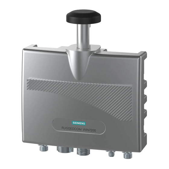
Installation Guide Introduction Section 1.2 Description The RUGGEDCOM WIN7258 features various types of ports for connecting antennas and data adapters, and for interfacing with the device. Figure 1: RUGGEDCOM WIN7258 1. ANT 2 Port 2. RS-232 Serial Console Port 3. DC/ETH Port 4. GPS Port 5. ANT 1 Port... -
Page 12: Decomissioning And Disposal
Chapter 1 RUGGEDCOM WIN7258 Introduction Installation Guide Sprays Mounting Hardware (Wall/Tower Only) • Cleaner and de-greaser • Four 8 mm (5/16 in) screws • SCC3 conformal coating • Four 8 mm (5/16 in) flat washers • Corrosion protection • Four 8 mm (5/16 in) spring washers •... -
Page 13: Installing The Base Station
WARNING! Safety hazard – risk of serious personal injury and/or damage to equipment. Installing the RUGGEDCOM WIN7258 can pose a serious safety hazard. Be sure to take precautions to avoid the following: • Exposure to high voltage lines during installation •... -
Page 14: General Procedure
Chapter 2 RUGGEDCOM WIN7258 Installing the Base Station Installation Guide IMPORTANT! Install equipment in accordance with the electrical code relevant to the country of installation, such as: • the National Electrical Code (NEC), ANSI/NFPA 70 • the Canadian Electrical Code (CEC), Part 1, CSA C22.1 •... -
Page 15: Unpacking The Base Station
11. Configure the base station. For more information, refer to Section 3.2, “Configuring the Base Station”. Section 2.2 Unpacking the Base Station The following items are included in the RUGGEDCOM WIN7258 package: Item Quantity RUGGEDCOM WIN7258 Base Station Pole/wall/tower mounting kit DB9 Female to 3-Pin Male RS232 Cable, 2 m (6.6 ft) -
Page 16: Site Preparation And Precautions
When installing the base station or an antenna, make sure to adhere to the following safety precautions: • Always install the base station with the help of a partner. • Always use the most appropriate mounting method for the site and the equipment being installed. For assistance, contact a Siemens representative. Site Preparation and Precautions... -
Page 17: Installing The Base Station In Hazardous Locations
Installing the Base Station in Hazardous Locations The RUGGEDCOM WIN7258 is designed to comply with the safety standards for Class I, Division 2, Zone 2 hazardous locations where concentrations of flammable gases, vapors or liquids may be present, as opposed to normal operating environments. -
Page 18: Mounting The Base Station
Chapter 2 RUGGEDCOM WIN7258 Installing the Base Station Installation Guide WARNING - EXPLOSION HAZARD P/N: WiN72XX-Y DO NOT SEPARATE WHILE CIRCUIT IS LIVE UNLESS AREA IS KNOWN TO BE SAFE Pico Base Station AVERTISSEMENT - RISQUE D'EXPLOSION NE PAS DÉBRANCHER TANT QUE LE CIRCUIT EST SOUS TENSION, S/N: À... -
Page 19: Mounting The Base Station To A Pole
RUGGEDCOM WIN7258 Chapter 2 Installation Guide Installing the Base Station Liberally apply an anti-corrosion spray to all galvanized steel components, including mounting brackets, washers and screws. Select a mounting location on the wall. Align the mounting bracket with the selected mounting location on the wall/tower. -
Page 20: Assembling The Base Station And Mounting Bracket
Chapter 2 RUGGEDCOM WIN7258 Installing the Base Station Installation Guide Attach the base station to the mounting bracket. For more information, refer to Section 2.5.3, “Assembling the Base Station and Mounting Bracket”. Liberally apply an anti-corrosion spray to all galvanized steel components, including mounting brackets, nuts, washers and screws. -
Page 21: Installing Antennas
• Make sure the antenna is accessible for maintenance. CONTENTS • Section 2.6.1, “Installing an RF Antenna” • Section 2.6.2, “Installing an External GPS Antenna” Section 2.6.1 Installing an RF Antenna The RUGGEDCOM WIN7258 base station supports two (primary and secondary) external omni-directional or directional Radio Frequency (RF) antennas. Installing Antennas... - Page 22 IMPORTANT! A Radio Frequency (RF) site survey is recommended prior to any installation to help determine the best location for the antenna(s). For assistance, contact a Siemens Sales representative. To install an RF antenna, do the following: Mount the antenna to a pole or wall in an area that provides good signal coverage and is away from any signal noise emanating from other communications equipment.
-
Page 23: Installing An External Gps Antenna
Section 2.6.2 Installing an External GPS Antenna The RUGGEDCOM WIN7258 base station is equipped with an internal omni-directional GPS antenna. This is ideal for indoor applications, but for outdoor applications, an external antenna may be required. The application may also require a directional – as opposed to omni-directional – antenna. -
Page 24: Grounding The Base Station
Chapter 2 RUGGEDCOM WIN7258 Installing the Base Station Installation Guide Section 2.7 Grounding the Base Station The base station is considered to be connected to a centralized DC power system. Therefore, the power cable should be grounded. The base station should be permanently connected to ground/Earth with a 10 AWG cable. -
Page 25: Connecting To A Ruggedcom Rp100 Or Rp110
Connecting to a RUGGEDCOM RP100 or RP110 The RUGGEDCOM RP100 and RP110 are optional power injectors for powering and providing data to the RUGGEDCOM WIN7258. The RUGGEDCOM RP100 and RP110 meet a wider temperature and voltage range than the standardRUGGEDCOM WIN1010. -
Page 26: Connecting The Data Adapter
Electrical hazard – risk of damage to equipment. The power cord provided with the data adapter is safety certified according to national rules. Do not use a power cord that has not been approved by Siemens for use with the data adapter. IMPORTANT! Only use the supplied data adapter with the base station. -
Page 27: Assembling The Poe Connector
RUGGEDCOM WIN7258 Chapter 2 Installation Guide Installing the Base Station Section 2.8.3 Assembling the PoE Connector A custom PoE cable with a special RJ45 connector is required to connect a PoE injector to the DC/ETH port. The following materials and tools are required: •... - Page 28 Chapter 2 RUGGEDCOM WIN7258 Installing the Base Station Installation Guide Figure 12: Folding Back the Foil 1. Foil 2. Twisted-Pair Wires 3. Drain Wire Bend the drain wire back over the jacket. Figure 13: Bending the Drain Wire 1. Foil 2. Drain Wire 3. Twisted-Pair Wires Partially untwist each wire pair, making sure to retain a half twist at the end.
- Page 29 RUGGEDCOM WIN7258 Chapter 2 Installation Guide Installing the Base Station Color Description Number White/Orange ETH Data TP0+ Orange ETH Data TP0- White/Green ETH Data TP1+ Figure 15: CAT-5e PoE Cable Pin-Out Blue 55 V TP2+ 1. Pin 1 2. Pin 8 White/Blue 55 V...
-
Page 30: Installing The Hazardous Location Kit
An approved surge suppression unit is required when the base station is installed in a hazardous location. The RUGGEDCOM WIN7258 is certified for installation in Class I, Division 2 Groups A, B, C and D hazardous locations when installed using the Class I, Division 2 kit (P/N MKIT0090). The Class I, Division 2 kit contains the following items: •... -
Page 31: Weatherproofing The Base Station
RUGGEDCOM WIN7258 Chapter 2 Installation Guide Installing the Base Station Figure 18: Connecting the Base Station in a Hazardous Location 1. Ethernet Switch 2. CAT-5e Cable 3. PoE Injector 4. Base Station 5. DC Power Cable 6. Power Supply Unit Using a CAT-5e cable, connect the PoE injector to he DC/ETH port on the base station. -
Page 32: Weatherproofing A Cable
Most outdoor base station, antenna and cable problems are caused by coaxial cable connections loosened by vibration, allowing moisture to penetrate the connector interface. Siemens strongly recommends weatherproofing all outdoor cable connections to prevent the ingress of water and help secure connections. -
Page 33: Applying Self-Amalgamating Tape
RUGGEDCOM WIN7258 Chapter 2 Installation Guide Installing the Base Station Hold the tube against the base station chassis and start rotating it clockwise while gently pulling out the core. Stop rotating once the front end of the cold shrink has begun to form around the cable end. - Page 34 Chapter 2 RUGGEDCOM WIN7258 Installing the Base Station Installation Guide Applying Self-Amalgamating Tape...
-
Page 35: Device Management
RUGGEDCOM WIN7258 Chapter 3 Installation Guide Device Management Device Management This section describes how to connect to and manage the base station. CONTENTS • Section 3.1, “Connecting to the Base Station” • Section 3.2, “Configuring the Base Station” Section 3.1 Connecting to the Base Station The following describes the various methods for accessing the RUGGEDCOM WIN console and Web interfaces on the base station. -
Page 36: Configuring The Base Station
Reserved (Do Not Connect) For information about how to connect to the device via the serial console port, refer to the RUGGEDCOM WIN User Guide for the RUGGEDCOM WIN7258. Accessing the Web Interface The access the Web interface for RUGGEDCOM WIN, do the following: Connect a PC to the switch/router that is on the same network as the base station. -
Page 37: Technical Specifications
10 to 60 VDC 88 to 300 VDC RUGGEDCOM RP100 or RP110 Section 4.2 Power Supply Requirements The RUGGEDCOM WIN7258 requires an external power supply that meets the following requirements: Power Supply Rated Input Power Rated Output Power RUGGEDCOM WIN1010 100 to 240 VAC, 50 to 60 Hz, 1.5 A... -
Page 38: Radio And Modem Specifications
-60 to 100 dBm Dynamic Range (Transmitter) 6 to 21 dBm Section 4.4 Operating Environment The RUGGEDCOM WIN7258 can operate under the following environmental conditions: Ambient Operating -40 to 70 °C (-40 to 158 °F) Temperature Ambient Storage Temperature -40 to 70 °C (-40 to 158 °F) -
Page 39: Mechanical Specifications
RUGGEDCOM WIN7258 Chapter 4 Installation Guide Technical Specifications Section 4.5 Mechanical Specifications Weight (Base Station) 3.2 kg (7.1 lbs) Weight (Mounting Bracket) 0.6 kg (1.2 lbs) Ingress Protection IP67 Chassis Material Aluminum Section 4.6 IDU-to-ODU Cable Specifications The following outlines the technical specifications for the Indoor Unit (IDU) to Outdoor Unit (ODU) cable required to assemble the Power-over-Ethernet (PoE) connector. -
Page 40: Dimension Drawings
Chapter 4 RUGGEDCOM WIN7258 Technical Specifications Installation Guide Overall Drain-Wire Gage 24 AWG Overall Drain-Wire Stranded Construction Outer Jacket Material UV resistant FR-PVC Inner Jacket Material UV resistant FR-PVC Inner Jacket Diameter 6.1 mm (0.24 in) External Diameter 8 mm (0.3 in) - Page 41 RUGGEDCOM WIN7258 Chapter 4 Installation Guide Technical Specifications 85.4 228.4 Figure 20: RUGGEDCOM WIN7258 Dimensions without Mounting Bracket 112.5 106.0 51.0 Figure 21: RUGGEDCOM WIN7258 Dimensions with Mounting Bracket Dimension Drawings...
- Page 42 Chapter 4 RUGGEDCOM WIN7258 Technical Specifications Installation Guide Dimension Drawings...
-
Page 43: Certification
RUGGEDCOM WIN7258 Chapter 5 Installation Guide Certification Certification The RUGGEDCOM WIN7258 base station has been thoroughly tested to guarantee its conformance with recognized standards and has received approval from recognized regulatory agencies. CONTENTS • Section 5.1, “Approvals” • Section 5.2, “EMC and Environmental Type Tests”... -
Page 44: Csa
Chapter 5 RUGGEDCOM WIN7258 Certification Installation Guide It is specifically approved for use in hazardous locations defined as: • Class I, Division 2, Groups A, B, C, D T4 • Ex nA nC IIC T4 Gc X II 3G Notices specific to MET Laboratories:... -
Page 45: Ised
Siemens”. Section 5.1.4 ISED This base station is declared by Siemens Canada Ltd to meet the requirements of the following ISED (Innovation Science and Economic Development Canada) standard: • RSS-102 Radio Frequency (RF) Exposure Compliance of Radiocommunication Apparatus (All Frequency Bands) •... -
Page 46: Rohs
Tests – Method 509.4 (Salt Fog) Section 5.1.7 RoHS This device is declared by Siemens Canada Ltd to meet the requirements of the following RoHS (Restriction of Hazardous Substances) directives for the restricted use of certain hazardous substances in electrical and electronic equipment: •... - Page 47 RUGGEDCOM WIN7258 Chapter 5 Installation Guide Certification Standard Method Description Test Levels IEC 60068-2-6 IEC 61850-3 (5.5) Vibration 2 g (32 ft/s ), 10-150 Hz per Axis IEC 61000-4-6 IEC 61850-3 Conducted Immunity 10 Vrms (5.7.1.1) IEC 61000-4-5 IEC 61850-3...
- Page 48 Chapter 5 RUGGEDCOM WIN7258 Certification Installation Guide Standard Method Description Test Levels 35 V/m (modulated) IEC 61000-4-2 IEEE 1613 (9) 8 kV Contact, 15 kV Air IEEE C37.90.3 Insulation IEC 60255-5 (6.1.3) IEEE 1613 (6.3 HV Impulse 5 kV IEC 60255-5 (6.1.4) IEEE 1613 (6.2)
Need help?
Do you have a question about the RUGGEDCOM WIN7258 and is the answer not in the manual?
Questions and answers