Table of Contents
Advertisement
Quick Links
SIWAREX WP241
Weighing systems
Electronic weighing system
SIWAREX WP241
Manual
04/2014
A5E33713528A
___________________
Introduction
___________________
Safety guidelines
___________________
Description
___________________
Application planning
___________________
Installation
___________________
Connecting
___________________
Commissioning
Scale parameters and
___________________
functions of the belt scale
___________________
Messages
___________________
Command lists
___________________
Communication
___________________
Technical specifications
___________________
Accessories
___________________
ESD guidelines
___________________
List of abbreviations
1
2
3
4
5
6
7
8
9
10
11
12
13
A
B
Advertisement
Table of Contents

Related Manuals for Siemens SIWAREX WP241


Summary of Contents for Siemens SIWAREX WP241
- Page 1 ___________________ SIWAREX WP241 Introduction ___________________ Safety guidelines ___________________ Description Weighing systems ___________________ Application planning Electronic weighing system ___________________ SIWAREX WP241 Installation ___________________ Connecting Manual ___________________ Commissioning Scale parameters and ___________________ functions of the belt scale ___________________ Messages ___________________ Command lists...
- Page 2 Note the following: WARNING Siemens products may only be used for the applications described in the catalog and in the relevant technical documentation. If products and components from other manufacturers are used, these must be recommended or approved by Siemens. Proper transport, storage, installation, assembly, commissioning, operation and maintenance are required to ensure that the products operate safely and without any problems.
-
Page 3: Table Of Contents
6.3.1 Connection of an MLC / MBS / MUS / MCS / MSI / MMI belt scale to WP241 ......28 6.3.2 Connection of any scales or load cells ..................29 Shield connection ......................... 31 SIWAREX WP241 Manual, 04/2014, A5E33713528A... - Page 4 Setting up a network ........................63 7.6.4 Online parameter assignment ..................... 64 7.6.5 Available help options ......................... 64 7.6.6 Entering parameters with SIWATOOL ..................65 7.6.7 Recording scale traces ........................ 65 7.6.8 Firmware update ......................... 66 SIWAREX WP241 Manual, 04/2014, A5E33713528A...
- Page 5 Result calculator........................... 89 DR 5 Correction factors for material flow rate ................90 8.7.1 Belt load factor 1 .......................... 91 8.7.2 Belt load factor 2 .......................... 91 8.7.3 Correction factors 1 and 2 ......................91 SIWAREX WP241 Manual, 04/2014, A5E33713528A...
- Page 6 Subnet mask ..........................110 8.13.5 Gateway ............................ 110 8.13.6 Device name ..........................110 8.14 DR 13 RS485 parameters ......................111 8.14.1 RS485 protocol ......................... 112 8.14.2 RS485 baud rate ........................112 8.14.3 RS485 character parity ......................112 SIWAREX WP241 Manual, 04/2014, A5E33713528A...
- Page 7 Error code following commands at digital input ................. 132 8.25 DR 33 Totalizers ........................133 8.25.1 Current master totalizer (S1) ...................... 134 8.25.2 Current main totalizer (S2) ......................134 8.25.3 Totalizer 3 (S3), totalizer 4 (S4), totalizer 5 (S5) ............... 134 SIWAREX WP241 Manual, 04/2014, A5E33713528A...
- Page 8 Command mailboxes ........................ 163 11.2.5 Reading registers ........................164 11.2.6 Writing registers ........................165 Technical specifications ........................167 12.1 Technical specifications ......................167 12.2 Electrical, EMC and climatic requirements ................172 12.3 Approvals ..........................176 Accessories ............................177 SIWAREX WP241 Manual, 04/2014, A5E33713528A...
- Page 9 Table of contents ESD guidelines ........................... 179 ESD Guidelines .......................... 179 List of abbreviations ..........................181 List of abbreviations ........................181 Index..............................183 SIWAREX WP241 Manual, 04/2014, A5E33713528A...
- Page 10 Table of contents SIWAREX WP241 Manual, 04/2014, A5E33713528A...
-
Page 11: Introduction
Introduction Purpose of the manual This manual contains all necessary information on the setup, installation, wiring and commissioning of the SIWAREX WP241 electronic weighing system. Basic knowledge required This manual requires basic knowledge of weighing technology. When used in the SIMATIC S7-1200, basic knowledge of the SIMATIC S7-1200 automation system and the TIA Portal are required. - Page 12 ● Information about field service, repairs, spare parts and lots more under "Services". Additional Support Please contact your local Siemens representative and offices if you have any questions about the products described in this manual and do not find the right answers.
-
Page 13: Safety Guidelines
The specifications of the manual for the SIMATIC S7-1200 system apply to configuration, installation and commissioning in the SIMATIC environment. This chapter includes additional information on hardware configuration, installation and preparation for operation of the SIWAREX WP241. The safety notes must be observed. Note The device was developed, manufactured, tested and documented in compliance with the relevant safety standards. - Page 14 2.1 General safety instructions IT security Siemens provides automation and drive products with industrial security functions that support the secure operation of plants or machines. They are an important component in a holistic industrial security concept. With this in mind, our products undergo continuous development.
-
Page 15: Description
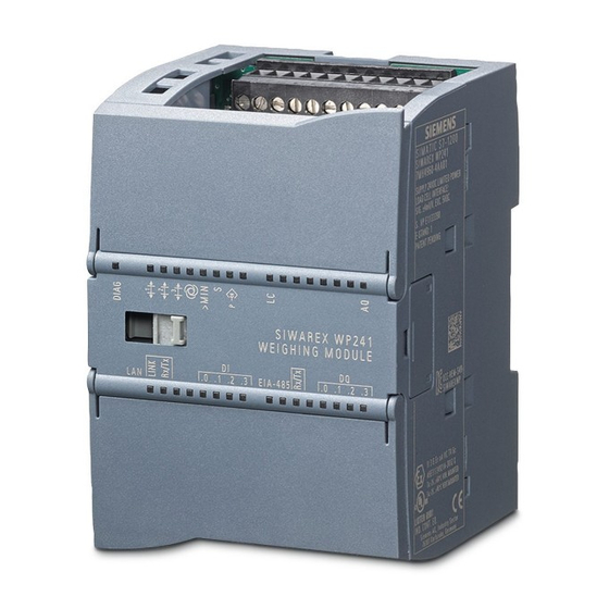
Description Product overview SIWAREX WP241 is a versatile and flexible weighing module that can be operated as a belt scale. The electronic weighing system can be used in SIMATIC S7-1200 and uses all features of a modern automation system, such as integrated communication, operation and monitoring, the diagnostic system as well as the configuration tools in the TIA Portal. -
Page 16: Customer Benefits
The scope of delivery only includes the SIWAREX WP241 weighing module. Note We recommend that you use the SIWAREX WP241 configuration package for configuring the SIWAREX WP241 electronic weighing system. The configuration package is not included in the scope of delivery of the module: → Accessories (Page 177). -
Page 17: Application Planning
The integration in SIMATIC gives you the option to process the weight value directly in the PLC (ProgrammabelLogic Controller). The SIWAREX WP241 is calibrated at the factory. This allows for automatic calibration of the scales without the need for calibration weights and replacement of modules without the need for recalibrating the scales. -
Page 18: Parameter Assignment Options
The display of the current scale status can be configured. You can switch between several languages in the program. SIWAREX WP241 Manual, 04/2014, A5E33713528A... -
Page 19: Parameter Assignment With A Simatic Panel
All parameters can be assigned and the module put into operation using a SIMATIC HMI Panel connected to the S7-1200 CPU and the SIWAREX WP241 function and data blocks. The Ready-for-Use software is included in the scope of delivery of the configuration package. - Page 20 Application planning 4.2 Parameter assignment options SIWAREX WP241 Manual, 04/2014, A5E33713528A...
-
Page 21: Installation
● Interferences transported by communication cables ● Interferences having an effect via process cables ● Interferences entering the system via the power supply and/or protective ground Interferences can impair the fault-free functioning of the electronic weighing system. SIWAREX WP241 Manual, 04/2014, A5E33713528A... -
Page 22: Coupling Mechanisms
● Always route high-voltage and data cables in separate ducts or in separate bundles. ● Install the measurement cables as close as possible to grounded surfaces (e.g. supporting beans, metal rails, steel cabinet walls). SIWAREX WP241 Manual, 04/2014, A5E33713528A... -
Page 23: Mounting On The Simatic S7-1200
The load cells, power supply and serial interfaces are connected via the screw-type connectors. Use of the WP241 in the SIMATIC TIA Portal is described in detail in chapter 11 of this manual: → Integration in SIMATIC S7-1200 (Page 153) SIWAREX WP241 Manual, 04/2014, A5E33713528A... - Page 24 Installation 5.3 Mounting on the SIMATIC S7-1200 SIWAREX WP241 Manual, 04/2014, A5E33713528A...
-
Page 25: Connecting
Analog output connection Ethernet interface connection ③ ⑧ Load cell connection Calibration bridge connection ④ ⑨ RS485 interface connection Mounting terminals for the calibration protection plate ⑤ Digital output connection Figure 6-1 SIWAREX WP241 connection areas SIWAREX WP241 Manual, 04/2014, A5E33713528A... -
Page 26: Connection
Ground voltage supply Connecting the load cells Overview Pickups can be connected to the SIWAREX WP241 electronic weighing system which are equipped with strain gauges (full bridge) and meet the following requirements. ● Characteristic value 1 to 4 mV/V ● A supply voltage of 5 V is permitted ●... - Page 27 We recommended that you use the cables listed in chapter → Accessories (Page 177). 3. The shield must be connected to ground directly in the vicinity of the SIWAREX WP241. The maximum distance between the SIWAREX WP241 and the load cell applies when using the recommended cables (see SIWAREX cables →...
-
Page 28: Connection Of An Mlc / Mbs / Mus / Mcs / Msi / Mmi Belt Scale To Wp241
Connection of an MLC / MBS / MUS / MCS / MSI / MMI belt scale to WP241 The following graphic clarifies the interfacing of all Siemens belt scale types to SIWAREX WP241. When using several MSI scales (MMI2 or MMI3) installed in sequence, all additional load cells are connected in parallel in the junction box as shown in the graphic. -
Page 29: Connection Of Any Scales Or Load Cells
Connecting 6.3 Connecting the load cells 6.3.2 Connection of any scales or load cells Figure 6-4 Connection of 4-wire load cells to WP241 SIWAREX WP241 Manual, 04/2014, A5E33713528A... - Page 30 Connecting 6.3 Connecting the load cells Figure 6-5 Connection of 6-wire load cells to WP241 SIWAREX WP241 Manual, 04/2014, A5E33713528A...
-
Page 31: Shield Connection
Use only cables with protective braided shield (see recommended cables of load cells in chapter Accessories (Page 177)). Shielding density must be at least 80%. Figure 6-6 Shield connection element fitting (example) SIWAREX WP241 Manual, 04/2014, A5E33713528A... -
Page 32: Connection Of Digital Outputs (4 X Dq)
Labeling Function DQ.0 Digital output 0 DQ.1 Digital output 1 DQ.2 Digital output 2 DQ.3 Digital output 3 DQ.3L+ +24 V DC power supply for digital outputs DQ.3M Ground of power supply for digital outputs SIWAREX WP241 Manual, 04/2014, A5E33713528A... -
Page 33: Connection Of Digital Inputs (4 X Di)
Connection of the digital inputs Labeling Function DI.0 Digital input 0 (input for speed sensor) DI.1 Digital input 1 DI.2 Digital input 2 DI.3 Digital input 3 DI.2M Reference ground potential of the digital inputs SIWAREX WP241 Manual, 04/2014, A5E33713528A... -
Page 34: Connection Of The Analog Output (1 X Aq)
EIA-485 D- RS485 data line - for feeding in of bus signal If a SIWAREX WP241 module forms the termination of an RS485 network, insert wire jumpers between the D+‘ and T+ terminals and between the D-‘ and T- terminals for termination of the bus network. -
Page 35: Connection Of The Ethernet Interface
6.10 Activation of write protection In the case of an officially verified SIWAREX WP241, write protection must be provided to prevent the changing of data relevant to the calibration. Insert a wire jumper between the module terminals P and PR for this purpose. -
Page 36: Mounting Of The Calibration Protection Plate
6.11 Mounting of the calibration protection plate In order to be able to operate the SIWAREX WP241 with verification capability in the future, the load cell connections must be protected against manipulation. To achieve this, mount the calibration protection plate included in the calibration set as shown in the following picture. -
Page 37: Connection Of A Speed Sensor
7 during commissioning. Connection of the various Siemens speed sensors is shown below. A wide range of pulse sensors can be used up to a clock frequency of 5 000 Hz. A level of at least +15 V DC is required for the High signal. -
Page 38: Tass Speed Sensor On Wp241
Connecting 6.12 Connection of a speed sensor 6.12.2 TASS speed sensor on WP241 Figure 6-9 TASS speed sensor on WP241 6.12.3 WS100 speed sensor on WP241 Figure 6-10 WS100 speed sensor on WP241 SIWAREX WP241 Manual, 04/2014, A5E33713528A... -
Page 39: Ws300 Speed Sensor On Wp241
Connecting 6.12 Connection of a speed sensor 6.12.4 WS300 speed sensor on WP241 Figure 6-11 WS300 speed sensor on WP241 SIWAREX WP241 Manual, 04/2014, A5E33713528A... - Page 40 Connecting 6.12 Connection of a speed sensor SIWAREX WP241 Manual, 04/2014, A5E33713528A...
-
Page 41: Commissioning
Factory-set parameters The electronic weighing system described here is provided with factory-set parameters. Parameters which can be entered in % or time are preset in such a way that they provide good results for most applications. SIWAREX WP241 Manual, 04/2014, A5E33713528A... -
Page 42: Factory Setting Of The Mode Selector
● SIWATOOL The SIWATOOL program allows you to commission the scale without an Operator Panel and without an automation system. In the event of a fault, additional SIWATOOL diagnostics functions enable fast analysis of the cause. SIWAREX WP241 Manual, 04/2014, A5E33713528A... -
Page 43: Start-Up With The Operator Panel And The Ready-For-Use Software
The square in the top right corner is then colored yellow (= Service mode ON). You can subsequently use the button with triangle at the bottom right to reach the submenu "1.1.1 Basic parameters 1 of 2". SIWAREX WP241 Manual, 04/2014, A5E33713528A... - Page 44 Once the parameters have been appropriately set for your system, confirm them using the save button (diskette symbol) and move on to the next input form using the button with triangle at the bottom right. SIWAREX WP241 Manual, 04/2014, A5E33713528A...
-
Page 45: Commissioning With Speed Sensor
"Nominal belt speed" parameter is only used as a reference for the speed limits. Use the "Door symbol" at the bottom left to return to the Setup menu. In the next step, calibrate your scale using the instructions and parameters under item "1.2 Calibration". SIWAREX WP241 Manual, 04/2014, A5E33713528A... -
Page 46: Specification Of A Pulse Constant
= diameter of guide pulley in meters The inputs are completed using the save button (diskette symbol). Then move on to the "Zero calibration" using → Zero calibration (Page 53). Figure 7-4 Specification of pulse constant SIWAREX WP241 Manual, 04/2014, A5E33713528A... -
Page 47: Pulse Constant Calculation
Import the result using the "Apply new constant" button. If the values have been applied successfully, the "Pulse / length unit" parameter underneath "New value" becomes zero. Then move on to the "Zero calibration" using → Zero calibration (Page 53). SIWAREX WP241 Manual, 04/2014, A5E33713528A... -
Page 48: Commissioning Without Speed Sensor
● From the operator panel (menu 1.4.5) You can reset the speed to zero again using the "Reset "Belt is running"" command. Then move on to the "Zero calibration" using → Zero calibration (Page 53). SIWAREX WP241 Manual, 04/2014, A5E33713528A... -
Page 49: Determination Of Current Belt Speed (Belt Empty)
DI.1. Pulses are then counted at input DI.1 according to the parameterized number of belt revolutions, and an exact trigger point is thus achieved. Then move on to the "Zero calibration" using → Zero calibration (Page 53). SIWAREX WP241 Manual, 04/2014, A5E33713528A... -
Page 50: Determination Of Current Belt Speed (Belt Loaded)
Prerequisites for determination of the characteristic are: ● Speed calculation has been carried out with empty belt ● Successful zero calibration ● Successful span calibration If these conditions have been fulfilled, move on to menu item 1.2.1.3. SIWAREX WP241 Manual, 04/2014, A5E33713528A... - Page 51 "Trigger belt revolution recording" function to DI.1. Pulses are then counted at input DI.1 according to the parameterized number of belt revolutions, and an exact trigger point is thus achieved. SIWAREX WP241 Manual, 04/2014, A5E33713528A...
-
Page 52: External Specification Of A Speed
0 into data record 19 and send this to the electronics. Following a power loss, a value of 0 is used automatically, and you must again send the current speed externally. SIWAREX WP241 Manual, 04/2014, A5E33713528A... -
Page 53: Zero Calibration
(Page 53). 7.5.5 Span calibration There are four options for the span calibration: ● Using reference weights ● Using a test chain ● Using a material batch ● Automatically using entered load cell data SIWAREX WP241 Manual, 04/2014, A5E33713528A... -
Page 54: Span Calibration By Weight
You can improve the results for your system even further following completion of the calibration or also during subsequent operation by means of a flow correction by material test ( → Determination of a correction factor (Page 59)). SIWAREX WP241 Manual, 04/2014, A5E33713528A... -
Page 55: Span Calibration By Test Chain
Further information on these and all other parameters can be found in chapter → Scale parameters and functions of the belt scale (Page 69). You can return to the main screen using the "Home" button (house symbol). SIWAREX WP241 Manual, 04/2014, A5E33713528A... -
Page 56: Span By Material Batch
"Stop calibration". Enter the amount of material in the "Conveyed amount of material" field if it has not yet been recorded. To do this, weigh the conveyed amount of material on a separate scale. SIWAREX WP241 Manual, 04/2014, A5E33713528A... -
Page 57: Automatic Span Calibration
Navigate in the span calibration menu to item "1.2.3.4 Automatic span by load cell data". Figure 7-14 Automatic span calibration A prerequisite for this step is a successful zero calibration. SIWAREX WP241 Manual, 04/2014, A5E33713528A... - Page 58 You can improve the results for your system even further following completion of the calibration or also during subsequent operation by means of a flow correction by material test ( → Determination of a correction factor (Page 59)). SIWAREX WP241 Manual, 04/2014, A5E33713528A...
-
Page 59: Determination Of A Correction Factor
You can use several correction factors for different belt loads by using the SIWATOOL service and commissioning tool. It is then possible to determine an additional correction SIWAREX WP241 Manual, 04/2014, A5E33713528A... - Page 60 Commissioning 7.5 Start-up with the operator panel and the Ready-for-Use software factor for a further, higher belt load. A correction characteristic is then produced depending on the belt load. SIWAREX WP241 Manual, 04/2014, A5E33713528A...
-
Page 61: Service With Siwatool Software
The program is included in the optional configuration package (7MH4960-4AK01). Install the SIWATOOL program on your PC for commissioning. A document for commissioning of the belt scale using SIWATOOL is also available in the Siemens Customer Support. 7.6.1 Windows and functions of SIWATOOL ①... -
Page 62: Offline Parameter Assignment
This reduces the setup time. You can thus prepare the parameters for several scales in your office, and subsequently transfer them to the electronic weighing system during setup. Data from one scale currently in operation can be exported and used to set up another scale. SIWAREX WP241 Manual, 04/2014, A5E33713528A... -
Page 63: Ip Address For Siwarex
"Primary Setup Tool". The program is included in the configuration package. Install the program "Primary Setup Tool". When started, the program can determine the Siemens devices present in the network. The MAC (Media Access Control) address can be read on the front of the SIWAREX module. -
Page 64: Online Parameter Assignment
If you move the mouse over a button or parameter, a corresponding help text is displayed. ● Help Click on the menu option "Help" to call up the SIWATOOL help. The Help can be opened separately. SIWAREX WP241 Manual, 04/2014, A5E33713528A... -
Page 65: Entering Parameters With Siwatool
Excel and then processed further. The commands for starting and stopping are present in the "Trace commands" group (yellow memory card icon) in SIWATOOL. All important measured values, messages and changes in status are recorded. Figure 7-18 Trace export SIWAREX WP241 Manual, 04/2014, A5E33713528A... -
Page 66: Firmware Update
3. Call the firmware download using the function key 4. Select the current firmware file under "Firmware Download". 5. Click the "Start transfer" button. Following the transfer, the SIWAREX module must be switched off and then on again. This activates the new firmware. SIWAREX WP241 Manual, 04/2014, A5E33713528A... - Page 67 Commissioning 7.6 Service with SIWATOOL software Figure 7-19 Downloading the firmware with SIWATOOL SIWAREX WP241 Manual, 04/2014, A5E33713528A...
- Page 68 Commissioning 7.6 Service with SIWATOOL software SIWAREX WP241 Manual, 04/2014, A5E33713528A...
-
Page 69: Scale Parameters And Functions Of The Belt Scale
Scale parameters and functions of the belt scale Parameters and functions The SIWAREX WP241 electronic weighing system can be used to design a belt scale in accordance with OIML R50. Approval in accordance with MID will be available soon. All parameters are set to default values in the factory. In the case of a previously used electronic weighing system, you can restore the configuration to factory settings using the "Load factory settings"... -
Page 70: Dr 3 Belt Scale Parameters
0: No verification USHORT 1011 (Page 73) 1: OIML R50 2: NTEP Book 44 Unit for belt load 0=kg/m, 1=lbs/foot USHORT 1012 (Page 73) Unit for flow rate 0=t/h, 1=kg/h, 2=T/h, 3=TL/h, USHORT 1013 (Page 74) 4=lbs/h SIWAREX WP241 Manual, 04/2014, A5E33713528A... - Page 71 Value input in KG or LB (depending FLOAT 1044 (Page 78) on selected unit for belt load) Span calibration digits ADC digits for test weight LONG 1000000 1046 (Page 78) Value input or imported from DR4 SIWAREX WP241 Manual, 04/2014, A5E33713528A...
- Page 72 (Page 79)(available soon) Minimum display size HMI SecureDisplay with verification USHORT 1058 in % of the HMI capability SecureDisplay with verification capability (Page 79) (available soon) Reserve USHORT Parameter for calculation of calibration points SIWAREX WP241 Manual, 04/2014, A5E33713528A...
-
Page 73: Scale Name
With the lbs/foot unit, the material flow rate can be specified in T/h, TL/h or lbs/h. Note If the jumper is closed to protect data with verification capability, the parameter can no longer be changed. SIWAREX WP241 Manual, 04/2014, A5E33713528A... -
Page 74: Unit For Flow Rate
EN 45501 (1*10**k, 2*10**k, 5*10**k]; k: -3 … 2) from 0.0001 to 50. Note If the jumper is closed to protect data with verification capability, the parameter can no longer be changed. SIWAREX WP241 Manual, 04/2014, A5E33713528A... -
Page 75: Resolution Of Master Totalizer
The input is made in the length unit from the belt load. Note If the jumper is closed to protect data with verification capability, the parameter can no longer be changed. SIWAREX WP241 Manual, 04/2014, A5E33713528A... -
Page 76: Number Of Belt Revolutions
The associated belt load factor (in % of nominal load) is specified for determination of the speed correction (→ Speed correction if belt loaded (Page 76)). You must observe the value in DR30 during the calculation and subsequently enter it. SIWAREX WP241 Manual, 04/2014, A5E33713528A... -
Page 77: Impulse Constant Speed Sensor
"Pulses per meter" or "Pulses per foot" depending on the selected unit. If the pulse constant is unknown, it can be calculated automatically by the SIWAREX WP241 using an exactly defined total belt length. Commands 70 and 71 are used for this purpose. -
Page 78: Calibration Quantity
The parameter defines the interface via which the data is provided for a display with verification capability: 0 - no display with verification capability 1 - HMI SecureDisplay via Ethernet 2 - HMI SecureDisplay via S7 CPU SIWAREX WP241 Manual, 04/2014, A5E33713528A... -
Page 79: Software Version For Hmi Securedisplay With Verification Capability
Minimum display size in % of the HMI SecureDisplay with verification capability This parameter is not yet effective since the function is in preparation. The smallest display size which can still be easily read is defined for representation of the display with verification capability. SIWAREX WP241 Manual, 04/2014, A5E33713528A... -
Page 80: Calibration Procedure
During initial commissioning, measurement of the speed is calibrated first. Calibration of the speed can be carried out for scales with or without a speed sensor. This is followed by calibration of the weight measurement – the span calibration. SIWAREX WP241 Manual, 04/2014, A5E33713528A... -
Page 81: Calibration Of The Speed
"Trigger for belt revolution detection on DI" (75)) and use it to measure the belt revolution. The defined number of belt revolutions is recorded following enabling by the command "Enable belt revolution detection on DI (74)". SIWAREX WP241 Manual, 04/2014, A5E33713528A... -
Page 82: Specification Of Known Speed Parameters
– DR3 → design speed = maximum speed of belt ● With an external speed input via DR19, you must enter the following parameters manually: – DR3 → design speed = maximum speed of belt SIWAREX WP241 Manual, 04/2014, A5E33713528A... -
Page 83: Calibration Of Weight Measurement
1. Stop the belt. 2. Enter a test weight appropriate to the measuring range in DR3 (e.g. 50% of the measuring range). 3. Attach this test weight to the scale or place it onto the scale. SIWAREX WP241 Manual, 04/2014, A5E33713528A... -
Page 84: Automatic Span Calibration With Load Cell Data
If the belt scale has not been installed exactly horizontally, enter the inclination angle of the belt in data record DR15 and send this to the scale. The characteristic curve has thus been determined. The scale can calculate the weight values for the complete measuring range. SIWAREX WP241 Manual, 04/2014, A5E33713528A... -
Page 85: Span Calibration By Test Chain
The result is displayed in DR4. 3. Import the working point into DR3 using the command "Apply span calibration digits" (89). The characteristic curve has thus been determined. The scale can calculate the weight values for the complete load range. SIWAREX WP241 Manual, 04/2014, A5E33713528A... -
Page 86: Span Calibration With Known Material Flow
(69). The result is displayed in DR4. 2. Import the working point into DR3 using the command "Apply span calibration digits" (89). The characteristic curve has thus been determined. The scale can calculate the weight values for the complete load range. SIWAREX WP241 Manual, 04/2014, A5E33713528A... -
Page 87: Dr 4 Temporary Parameters
Command for importing: "Apply pulse parameter" (87) Pulses per belt Pulses for one belt revolution, LONG 1212 revolution determination with empty belt using "Start/Stop belt revolution detection" commands Command for importing: "Apply pulse parameter" (87) SIWAREX WP241 Manual, 04/2014, A5E33713528A... - Page 88 Start/Stop via command or with LONG 1238 zeroing or calibration commands Result calculator Calculation in accordance with FLOAT 1240 (Page 89) multiply a*b or divide a/b command. a and b are specified in DR21 Reserve LONG 1242 SIWAREX WP241 Manual, 04/2014, A5E33713528A...
-
Page 89: Stop Watch
The display is in milliseconds. 8.6.2 Result calculator Data record DR 21 is used to enter digits for multiplication or division of two numbers. The result is displayed here following the calculation (commands 81 and 83). SIWAREX WP241 Manual, 04/2014, A5E33713528A... -
Page 90: Dr 5 Correction Factors For Material Flow Rate
Belt load factor 2 Belt load factor for correction FLOAT 1260 (Page 91) point 2 (in % of nominal belt load) Correction factors 1 Correction factor with belt load FLOAT 1262 and 2 (Page 91) factor 2 SIWAREX WP241 Manual, 04/2014, A5E33713528A... -
Page 91: Belt Load Factor 1
4 is compared with the actual amount. The ratio between the actual amount and the amount in totalizer 4 results in the correction factor. Correction factor = (amount of material weighed previously or subsequently) / (amount totalized by scale) SIWAREX WP241 Manual, 04/2014, A5E33713528A... -
Page 92: Dr 6 Limits
Delay for output of status display LONG 1284 limits (Page 95) for belt speed (in ms) Minimum belt load Min. belt load for status display FLOAT 1286 (Page 95) 'Minimum belt load violated' in % of nominal belt load SIWAREX WP241 Manual, 04/2014, A5E33713528A... - Page 93 Order no low pass Filter number 2*(1…5) SHORT 1304 filter (Page 96) Reserve FLOAT 1305 Reserve USHORT 1307 Depth average filter Depth of average filter for weight USHORT 1308 flow rate (Page 96) measurement (n x 10 ms) SIWAREX WP241 Manual, 04/2014, A5E33713528A...
-
Page 94: Negative And Positive Zero Offset In
Maximum belt speed Exceeding the maximum belt speed is displayed in the status area of the scale. The specification is made in % of the nominal belt speed which was specified during commissioning or calculated. SIWAREX WP241 Manual, 04/2014, A5E33713528A... -
Page 95: Delay For Belt Speed Limits
Violation of the limits for the belt load is delayed by the specified time. The specification is made in ms. 8.8.12 Medium load for totalizing Totalizing is not carried out below this value. The specification is made in % of the belt load. If "0" is specified, totalizing is bidirectional. SIWAREX WP241 Manual, 04/2014, A5E33713528A... -
Page 96: Frequency Low Pass Filter Weight/Belt Load/Belt Speed
10 ms. With n = 10, for example, 10 values are used to generate the mean value. The oldest value is discarded every 10 ms, and the newest value included in the calculation. SIWAREX WP241 Manual, 04/2014, A5E33713528A... -
Page 97: Dr 7 Process Interfaces
2 rw 0xFFFF 1318 output DQ 0, 1, 2, 100…131: Bit no. of the status flags 3 (Page 100) from bytes 0 to 3 (DR 30), but inverted 33: data record 18 34: S7 I/O modules SIWAREX WP241 Manual, 04/2014, A5E33713528A... - Page 98 Basis of analog value output: USHORT 2 rw 1325 source (Page 102) 0 = belt speed 1 = belt load 2 = material flow rate 3 = ext. specification DS17 4 = ext. specification S7 interface SIWAREX WP241 Manual, 04/2014, A5E33713528A...
- Page 99 External totalizer - amount per pulse: REAL 4 rw 1335 (Page 104) output of pulses for external totalizer Pulse duration in ms (output of pulses LONG 4 rw 1337 for external totalizers) Reserve LONG 4 rw 1339 SIWAREX WP241 Manual, 04/2014, A5E33713528A...
-
Page 100: Assignment Digital Input Di 0, 1, 2, 3
Bit no. of the status flags from bytes 0 to 3 (DR 30) 100 … 131 Bit no. of the status flags from bytes 0 to 3 (DR 30), but inverted Controlled via data record 18 Controlled via S7 I/O modules SIWAREX WP241 Manual, 04/2014, A5E33713528A... -
Page 101: Response Of Digital Outputs To Faults Or Simatic Stop
Value of DQ.1 following fault NOTICE Risk to the plant If an output is set following a fault (operating error), this can pose a risk for the plant. Ensure that the parameters are correctly set. SIWAREX WP241 Manual, 04/2014, A5E33713528A... -
Page 102: Analog Output Range
Output maximum value (24 mA, NAMUR) 8.9.9 Start value for the analog output This parameter defines the specified value at which 0 or 4 mA is output. The value can be greater or less than the end value. SIWAREX WP241 Manual, 04/2014, A5E33713528A... -
Page 103: End Value For The Analog Output
Recording every 10 s 8.9.13 Trace storage method This parameter is used to specify the response of the trace memory. Value Response Trace recording runs as circulating memory Trace is stopped when the trace memory is full SIWAREX WP241 Manual, 04/2014, A5E33713528A... -
Page 104: Load Per Pulse
The pulse duration is defined in ms. Make sure when setting the parameters that you only enter plausible combinations → pulse duration > (amount per pulse / material flow rate) SIWAREX WP241 Manual, 04/2014, A5E33713528A... -
Page 105: Dr 8 Date And Time
Data record length information USHORT 1342 Application Information about which USHORT 1343 application the DR belongs to Version identifier Information about current data USHORT 65635 1344 record version Date and time SIMATIC DTL format DTL#1970 1345 -01-01- 00:00:00.0 SIWAREX WP241 Manual, 04/2014, A5E33713528A... -
Page 106: Dr 9 Module Information
- designation OS version (loader) e.g. version n USHORT 'V ' 1379 - designation DRAM memory Flash memory USHORT 1380 Flash memory MRAM memory USHORT 1381 MRAM memory Memory type USHORT 1382 Reserve 1 FLOAT 1383 SIWAREX WP241 Manual, 04/2014, A5E33713528A... -
Page 107: Dr 10 Load Cell Parameters
(Page 108) Reserve Reserve FLOAT 1411 Reserve Reserve FLOAT 1413 Reserve 2 Reserve SHORT 1415 Reserve 3 Reserve USHORT 1416 Reserve 4 Reserve FLOAT 1417 Parameter for calculation of calibration points with theoretical calibration SIWAREX WP241 Manual, 04/2014, A5E33713528A... -
Page 108: Number Of Load Cells
Rated load of a load cell The rated load of a load cell is required for checking the maximum weighing range of the scales. The rated load is entered in the specified units of weight. SIWAREX WP241 Manual, 04/2014, A5E33713528A... -
Page 109: Dr 12 Ethernet Parameters
Gateway n.n.n.x USHORT 1527 Device name Current device name header UBYTE[2] 2 rw 1528 (Page 110) Current device name CHAR[32] 1529 Reserve 1 Reserve SHORT 1545 Reserve 2 Reserve FLOAT 1546 Reserve 3 Reserve FLOAT 1548 SIWAREX WP241 Manual, 04/2014, A5E33713528A... -
Page 110: Device Mac Address
Assign the subnet mask of your network. 8.13.5 Gateway If a gateway is used between the SIWAREX WP241 and the communication partner, enter the gateway address here. If a gateway is not present, enter the IP address of the SIWAREX module. -
Page 111: Dr 13 Rs485 Parameters
Bit 5 Reserve 1564.11 Bit 6 Reserve 1564.10 Bit 7 Reserve 1564.9 Bit 8 Reserve 1564.8 Bit 9 Reserve 1564.7 Bit 10 Reserve 1564.6 Bit 11 Reserve 1564.5 Bit 12 Reserve 1564.4 Bit 13 Reserve 1564.3 SIWAREX WP241 Manual, 04/2014, A5E33713528A... -
Page 112: Rs485 Protocol
Baud rate 9 600 bps 19 200 bps 38 400 bps 57 600 bps 115 000 bps 8.14.3 RS485 character parity This parameter defines the character parity for the RS485 interface. Value Character parity Even SIWAREX WP241 Manual, 04/2014, A5E33713528A... -
Page 113: Rs485 Number Of Data Bits
This parameter defines the Modbus address (1 to 230) for communication via the RS485 interface with the Modbus protocol. 8.14.7 Modbus RTU response delay This parameter defines the delay of a response to a data request by the Modbus RTU master (in ms). SIWAREX WP241 Manual, 04/2014, A5E33713528A... -
Page 114: Dr 15 Belt Angle
If the scale is automatically calibrated using the load cell parameters and if the scale is not installed exactly horizontally, you must subsequently enter the inclination angle of the belt. The input is made in degrees. SIWAREX WP241 Manual, 04/2014, A5E33713528A... -
Page 115: Dr 16 Simulation (Belt Speed And Belt Load)
Only use values for simulation of the belt speed which are within the speed range of the belt. The word "TEST" is displayed on the main display during simulation and a status bit is set. SIWAREX WP241 Manual, 04/2014, A5E33713528A... -
Page 116: Dr 17 Control Analog Output
Reserve SHORT 1594 Reserve 2 Reserve USHORT 1595 8.17.1 Analog output specification The value to be entered must be between the start value (Page 102) and the end value (Page 103) of the analog output. SIWAREX WP241 Manual, 04/2014, A5E33713528A... -
Page 117: Dr 18 Control Digital Output
Bit 5 Reserve 1600.11 Bit 6 Reserve 1600.10 Bit 7 Reserve 1600.9 Bit 8 Reserve 1600.8 Bit 9 Reserve 1600.7 Bit 10 Reserve 1600.6 Bit 11 Reserve 1600.5 Bit 12 Reserve 1600.4 Bit 13 Reserve 1600.3 SIWAREX WP241 Manual, 04/2014, A5E33713528A... -
Page 118: Definition For Digital Output Dq.0, 1, 2, 3
1601 8.18.1 Definition for digital output DQ.0, 1, 2, 3 Digital outputs 0 to 3 can be controlled using data record 18 with this parameter. This function can be used for commissioning purposes, for example. SIWAREX WP241 Manual, 04/2014, A5E33713528A... -
Page 119: Dr 19 External Speed
USHORT 65635 1605 version External speed The externally determined speed can be FLOAT 4 rw 1606 value sent to the scale. Reserve 1 Reserve SHORT 2 rw 1608 Reserve 2 Reserve USHORT 2 rw 1609 SIWAREX WP241 Manual, 04/2014, A5E33713528A... -
Page 120: Dr 20 Message Configuration
3001 Totalizer error 3004.12 2004 Trace memory full 3004.11 3002 Calibration procedure 3004.10 interrupted Reserve 3004.9 Reserve 3004.8 Reserve 3004.7 Reserve 3004.6 Reserve 3004.5 Reserve 3004.4 Reserve 3004.3 Reserve 3004.2 Reserve 3004.1 Reserve USHORT 3005.16 SIWAREX WP241 Manual, 04/2014, A5E33713528A... -
Page 121: Dr 21 Calculator
Data record length information USHORT Application Information about which application the USHORT data record belongs to Version identifier Information about current data record USHORT version Number a FLOAT Number b FLOAT Reserve 2 Reserve USHORT SIWAREX WP241 Manual, 04/2014, A5E33713528A... -
Page 122: Dr 30 Process State
3004.7 exceeded Reserve Not used 3004.6 Reserve Not used 3004.5 Belt is running Set if belt is running 3004.4 Totalizing active Set if totalizing is running 3004.3 Totalizing enabled Set if totalizing is enabled 3004.2 SIWAREX WP241 Manual, 04/2014, A5E33713528A... - Page 123 3006.14 1105 Overload 3006.12 1106 Underload 3006.11 1002 RAM error 3006.10 1102 ADC error 3006.9 1005 3006.8 1003 Checksum error data 3006.7 Reserve Reserve 3006.6 1004 Checksum error program 3006.5 Reserve 3006.4 1001 Watchdog 3006.3 SIWAREX WP241 Manual, 04/2014, A5E33713528A...
- Page 124 (S2) (Page 126) Reserve FLOAT 3028 Refresh counter for Refresh counter incremented by 1 if USHORT 3030 process values weight values were changed (Page 126) Reserve 1 Reserve SHORT 3031 Reserve 3 Reserve FLOAT 3032 SIWAREX WP241 Manual, 04/2014, A5E33713528A...
-
Page 125: Current Weight
The current speed used to calculate the material flow rate. The output is made in % of the maximum speed. 8.22.8 Current master totalizer (S1) The total material flow is summed after the start-up and switching-off of service mode. Resetting the total is only possible using the "Load factory settings" command. SIWAREX WP241 Manual, 04/2014, A5E33713528A... -
Page 126: Current Main Totalizer (S2)
Measured values are calculated every 10 ms in the SIWAREX module. A counter is incremented by 1 each time. Once the counter reaches the value 65536, it starts again from zero. The counter can be used as a time stamp for data record DR 30. SIWAREX WP241 Manual, 04/2014, A5E33713528A... -
Page 127: Dr 31 Process State Extended
USHORT 65535 3319 Reserve Reserve USHORT 65535 3320 Reserve Reserve USHORT 65535 3321 Current status of Current status of input .0 3322.16 input .0 Current status of Current status of input .0 3322.15 input .1 SIWAREX WP241 Manual, 04/2014, A5E33713528A... -
Page 128: Unfiltered Digit Value
8.23.2 Filtered digit value The filtered digit value (measurement of weight) is the internal measured value immediately after filtering. 8.23.3 Current load cell signal (mV) The current input voltage of the load cell(s) in mV. SIWAREX WP241 Manual, 04/2014, A5E33713528A... -
Page 129: Current Analog Output (Ma)
Measured values are calculated every 10 ms in the SIWAREX module. A counter is incremented by 1 each time. Once the counter reaches the value 65536, it starts again from zero. The counter can be used as a time stamp for data record DR 31. SIWAREX WP241 Manual, 04/2014, A5E33713528A... -
Page 130: Dr 32 Display Of Data And Operator Errors
Load cell parameter not plausible 3504.3 Reserve 3504.2 5107 Shifting characteristic not possible 3504.1 5199 Error in command to DI 3505.11 Reserve 3505.5 6003 Command cannot be executed since a 3505.4 similar command is already active SIWAREX WP241 Manual, 04/2014, A5E33713528A... - Page 131 Synchronous error code for USHORT 3511 code (Page 132) communication at the SIWATOOL interface Error code Synchronous error code caused by USHORT 3512 following command at the DIs commands at digital input (Page 132) Reserve USHORT 3513 SIWAREX WP241 Manual, 04/2014, A5E33713528A...
-
Page 132: Data And Operator Errors, Bytes 0 To 7
SIWATOOL interface. 8.24.5 Error code following commands at digital input The error code is displayed here of the error which was triggered last as a result of a command via the digital input. SIWAREX WP241 Manual, 04/2014, A5E33713528A... -
Page 133: Dr 33 Totalizers
Totalizer 3 (S3), Totalizer S3 FLOAT 3526 totalizer 4 (S4), Totalizer S4 FLOAT 3528 totalizer 5 (S5) Totalizer S5 FLOAT 3530 (Page 134) Totalizer 6 (S6) Totalizer S6 FLOAT 3532 (Page 134) Reserve FLOAT 3534 SIWAREX WP241 Manual, 04/2014, A5E33713528A... -
Page 134: Current Master Totalizer (S1)
(652)", and therefore indicates the total amount. You can therefore carry out material tests or calibrate the scale, for example, without recording the "transported material" (calibration weight, test chain) into the balance. You can reset the total S6 using command 674. SIWAREX WP241 Manual, 04/2014, A5E33713528A... -
Page 135: Dr 34 Ascii Main Display Value
Material flow rate Weight Flow rate in % Belt load Belt load in % Speed Speed in % Accumulated total Main total Totalizer S3 Totalizer S4 Totalizer S5 Totalizer S6 Official calibration Serial number Firmware version SIWAREX WP241 Manual, 04/2014, A5E33713528A... -
Page 136: Dr 38 Process State Extended
Current initial zero offset Current deviation from FLOAT 4516 original zero (in % of nominal (in % of nominal load) load) Reserve FLOAT 4518 Reserve LONG 4520 Reserve LONG 4522 Reserve LONG 4524 Reserve 3xLONG LONG 4526 SIWAREX WP241 Manual, 04/2014, A5E33713528A... -
Page 137: Dr 48 Date And Time 2
Month Month USHORT 6965 Day in month USHORT 6966 Hour Hour USHORT 6967 Minute Minute USHORT 6968 Second Second USHORT 6969 Millisecond Millisecond USHORT 6970 Day of the week Day of the week USHORT 6971 SIWAREX WP241 Manual, 04/2014, A5E33713528A... -
Page 139: Messages
● Output of the message buffer to the SIWATOOL program (takes place automatically) ● Output by means of function block as bit field in Scale data block ● Output by means of data records DR 30 and DR 32 in case of communication with a Modbus master SIWAREX WP241 Manual, 04/2014, A5E33713528A... -
Page 140: Evaluating Messages With The Help Of Siwatool
All messages of the SIWAREX module can be completely detected and processed in the controller with the help of the SIWAREX WP241 function block. The messages can be evaluated directly in a signaling system by means of a bit signaling area in the scale data block. -
Page 141: Message List
Undervoltage at sensor cables 1105 Overload 1105 Overload of scale (ca. 110%) 1106 Underload 1106 Underload of scale (ca. -10%) 1107 Legal trade display failure 1107 The SecureDisplay legal trade display no longer communicates with the module SIWAREX WP241 Manual, 04/2014, A5E33713528A... -
Page 142: Technology Error Message List
6003 Command cannot be executed since 6003 Desired command cannot be executed since a dynamic a dynamic procedure is already active command (calibration, zeroing) is already being executed. SIWAREX WP241 Manual, 04/2014, A5E33713528A... - Page 143 7020 Speed parameter or sensor 7020 The speed parameter or sensor parameter in DR3 is not parameter not plausible plausible. 7021 Units are not plausible 7021 The selected units are not plausible (mixing of metric and imperial parameters). SIWAREX WP241 Manual, 04/2014, A5E33713528A...
-
Page 144: Messages By Leds On The Module
Load cell(s) faulty LED 10 Not used LED 11 Not used LED 12 Not used LED 13 Not used LED 14 Not used LED 15 Not used LED 16 Analog output active Analog output faulty SIWAREX WP241 Manual, 04/2014, A5E33713528A... - Page 145 RS485 communication active LED 12 Not used LED 13 DQ.0 Digital output 0 active LED 14 DQ.1 Digital output 1 active LED 15 DQ.2 Digital output 2 active LED 16 DQ.3 Digital output 3 active SIWAREX WP241 Manual, 04/2014, A5E33713528A...
- Page 146 Messages 9.5 Message list SIWAREX WP241 Manual, 04/2014, A5E33713528A...
-
Page 147: Command Lists
→ Table 10-3 Commands 700 ... 899: HMI display switchover (DR34 – ASCII display) (Page 150) → Table 10-4 Commands 1000 ... : Basic functions for weighing commands (Page 151) → Table 10-5 Data record commands of SIWAREX WP241 (Page 151) → Table 10-6 Totalizing commands of SIWAREX WP241 (Page 152) See also... -
Page 148: Command Lists
DR10 can be used to calculate the span. If the belt has not been installed horizontally, the angle must be subsequently entered in DR15. The result is directly imported into DR3 and DR4 and is therefore immediately active. SIWAREX WP241 Manual, 04/2014, A5E33713528A... - Page 149 The numbers A and B from DR21 are multiplied together. The result is entered in DR4. Divide a / b The numbers A and B from DR21 are divided by each other. The result is entered in DR4. SIWAREX WP241 Manual, 04/2014, A5E33713528A...
- Page 150 Total S3 Displays the current totalizer S3 Total S4 Displays the current totalizer S4 Total S5 Displays the current totalizer S5 Total S6 Shows the current totalizer S6 Display calibration Displays the entered calibration regulations regulations SIWAREX WP241 Manual, 04/2014, A5E33713528A...
- Page 151 A digital input can also be used or parameterized for this. If the speed is sent to the module via DR19, this command is not necessary either! Table 10- 5 Data record commands of SIWAREX WP241 Command Command Description...
- Page 152 Command lists 10.2 Command lists Table 10- 6 Totalizing commands of SIWAREX WP241 Command Command Description code Start totalizing Starts the totalizing. In the basic state, totalizing of the module is always active and must be specifically deactivated by the user (command 652).
-
Page 153: Communication
Integration in SIMATIC S7-1200 11.1.1 General information A SIWAREX WP241 occupies 32 bytes each in the I/O areas of the CPU. The maximum number of SIWAREX WP241 weighing modules is defined as follows: S7-1212 CPU → up to two WP241 weighing modules S7-1214 CPU →... -
Page 154: Creating The Hardware Configuration
11.1.2 Creating the hardware configuration Starting with TIA Portal V13, the SIWAREX WP241 is integrated as standard in the hardware profile as an S7-1200 technology module. For TIA Portal V12 SP1, an HSP is available as download from the Siemens Customer Support. - Page 155 Figure 11-3 Start address of module in TIA Portal Figure 11-4 HW ID of module in TIA Portal Diagnostic interrupts can be optionally enabled or deactivated in the module properties. SIWAREX WP241 Manual, 04/2014, A5E33713528A...
-
Page 156: Calling Of Function Block
● Start address SIWAREX WP241: 68 (see → Creating the hardware configuration (Page 154)) ● HW ID SIWAREX WP241: 271 (see → Creating the hardware configuration (Page 154)) ● Instance data block number of SIWAREX WP241 function block: DB241 The function block can be integrated at the desired position in the user program using drag and drop. -
Page 157: Working With The Function Block
2 or 1 for processing of the respective command. Note Cyclic triggering of the CMD1 command mailbox makes it impossible to send commands in mailbox 2 or 3. SIWAREX WP241 Manual, 04/2014, A5E33713528A... - Page 158 The new calibration weight is now present in the SIWAREX and can be used. Service mode for the module should subsequently be switched off again using command "2". This procedure for reading and writing data records or parameters is identical for all data records. SIWAREX WP241 Manual, 04/2014, A5E33713528A...
-
Page 159: I/O Interface Of Function Block
Specification for analog output if this has assigned "S7 interface" as source in data record 7. DIGIT_OUTPUT (UINT) Specifications for digital outputs if these have been assigned as function "S7 interface" in data record 7. SIWAREX WP241 Manual, 04/2014, A5E33713528A... -
Page 160: Error Codes Of Function Block
Synchronous data operation error has occurred bo_StartUp Startup synchronization of module running Note If execution of the function block is faulty, the variables shown do not correspond to the actual status in the module. SIWAREX WP241 Manual, 04/2014, A5E33713528A... -
Page 161: Communication Via Modbus
Modbus RTU or the Ethernet interface with Modbus TCP/IP. It is possible to use both interfaces for the communication. Note The SIWAREX WP241 is designed for use in secure (closed) networks and does not have any protection against unauthorized data traffic. The following chapters describe the specifications for handling communication. The following functions can be executed: ●... -
Page 162: Data Record Concept
(Page 69) describes the data records, variables and functions, including the register addresses. The data records are always checked as complete data packets for plausibility. For this reason, you must follow a specific procedure to change individual parameters. SIWAREX WP241 Manual, 04/2014, A5E33713528A... -
Page 163: Command Mailboxes
Command mailbox 3: Low priority Variable Note Type Modbus registers CMD3_CODE Code of command to be executed USHORT CMD3_TRIGGER Trigger for starting the command USHORT CMD3_STATUS 0=job running; 1=job finished (1 cycle) USHORT CMD3_QUIT 0=no error; <>0=error code USHORT SIWAREX WP241 Manual, 04/2014, A5E33713528A... -
Page 164: Reading Registers
A current measured value is to be read out from DR 30. ⇒ The register can be directly requested because its contents are automatically refreshed in the SIWAREX module at the specified measuring rate of 100 Hz and are always available up-to-date. SIWAREX WP241 Manual, 04/2014, A5E33713528A... -
Page 165: Writing Registers
In addition, an online document is available for working with SIWAREX WP231 and Modbus → Modbus communication of WP231 (http://support.automation.siemens.com/WW/view/de/77913998). This document can also be applied when using a SIWAREX WP241 since the identification mechanisms are identical. SIWAREX WP241 Manual, 04/2014, A5E33713528A... - Page 166 Communication 11.2 Communication via Modbus SIWAREX WP241 Manual, 04/2014, A5E33713528A...
-
Page 167: Technical Specifications
3000d Resolution • (d=e) Error • percentage pi 0.5 µV/e Step voltage • Accuracy delivery state typ. 0.1% v.E. Sampling rate 100 Hz Input signal resolution ± 4 000 000 Measuring range ± 4 mV/V SIWAREX WP241 Manual, 04/2014, A5E33713528A... - Page 168 24 mA Error signal (if configured (FW)) 22 mA Max. load 600 Ω Temperature coefficient range ≤ ± 25 ppm/K v. E. Temperature coefficient zero point typ. ± 0.3 μA/K Linearity error ≤ 0.05 % SIWAREX WP241 Manual, 04/2014, A5E33713528A...
- Page 169 15 V DC at 2.5 mA Logical signal level 0 (max) 5 V DC at 1.0 mA Sampling rate (FW) 10 ms Filtering 0.2, 0.4, 0.8, 1.6, 3.2, 6.4 and 12.8 ms Electrical isolation 500 V DC SIWAREX WP241 Manual, 04/2014, A5E33713528A...
- Page 170 Cat-5e UTP cable • (unshielded) max. 100 m Cat-5e SF/UTP • cable (shielded) Dimensions and weights Table 12- 10 Technical specifications: Dimensions W x H x D 70 x 75 x 100 mm Weight 300 g SIWAREX WP241 Manual, 04/2014, A5E33713528A...
- Page 171 Free fall IEC 61131-2 For devices < 10 kg: • In product packaging: • IEC 60068-2-31: 300 mm drop height Test Ec, procedure 1 In shipping package: • 1.0 m drop height per 5 attempts • SIWAREX WP241 Manual, 04/2014, A5E33713528A...
-
Page 172: Electrical, Emc And Climatic Requirements
CSA C22.2, No. 142 1 500 V AC (shield and signals) UL508 Additional electrical circuits: Test voltage: 500 V AC or 707 V DC Test duration: ≥ 1 minute Short circuit current: ≥ 5 mA SIWAREX WP241 Manual, 04/2014, A5E33713528A... - Page 173 Electrostatic discharge (ESD) EN45501 2, 4, 6 kV direct/indirect • OIML R 76 ≥ 10 discharges pos/neg • < 10 s repeat time • Electrostatic air discharge (ESD) EN 61000-4-2 8 kV NAMUR NE21 EN 61326 SIWAREX WP241 Manual, 04/2014, A5E33713528A...
- Page 174 AD24V, Dehn&Söhne) NOTICE Radio interference is possible This is a device of class A. The device may cause radio interference in residential areas. Implement appropriate measures (e.g.: use in 8MC cabinets) to prevent radio interference. SIWAREX WP241 Manual, 04/2014, A5E33713528A...
- Page 175 12.2 Electrical, EMC and climatic requirements Ambient conditions The use of SIWAREX WP241 is intended under the following conditions in SIMATIC S7- 1200. Additionally observe the operating conditions of the S7-1200 system. Table 12- 15 Operating conditions in accordance with IEC 60721...
-
Page 176: Approvals
"Product Information - Use of SIWAREX modules in a Zone 2 Hazardous Area (http://support.automation.siemens.com/WW/llisapi.dll?aktprim=100&lang=en&referer=%2f WW%2f&func=cslib.cssearch&nodeid0=4000024&viewreg=WW&siteid=csius&extranet=sta ndard&groupid=4000002&objaction=cssearch&content=adsearch%2Fadsearch%2Easpx)". Note The currently valid approvals for SIWAREX WP241 are to be found on the module rating plate. → CE approval (http://support.automation.siemens.com/WW/view/de/65692972) → cULus approval (http://support.automation.siemens.com/WW/view/de/74442065) -
Page 177: Accessories
SIWAREX WP241 manual Free download from the Internet WP241 manuals in various languages (http://support.automation.siemens.com/WW/view /de/64722267/133300) SIWAREX WP241 "Ready for use" Free download from the Internet "Ready for use" (http://support.automation.siemens.com/WW/view /de/64722267/133100) Ethernet patch cable CAT5 To connect the SIWAREX to a PC (SIWATOOL), SIMATIC CPU, panel, etc. - Page 178 (EB) in hazardous area and Ex interface (Ex- for fixed laying Occasional bending is possible, • blue PVC insulating sheath, approx. 10.8 mm outer diameter For ambient temperature -20 to +70 °C • DIN rail grounding terminals for load cell cable 6ES5728-8MA11 SIWAREX WP241 Manual, 04/2014, A5E33713528A...
-
Page 179: Esd Guidelines
The electrostatic discharge current may lead to latent failure of a module, that is, this damage may not be significant immediately, but in operation may cause malfunction. SIWAREX WP241 Manual, 04/2014, A5E33713528A... - Page 180 In this way, the discharged energy can not affect the sensitive devices. Discharge your body before you start taking any measurements on a module. Do so by touching grounded metallic parts. Always use grounded measuring instruments. SIWAREX WP241 Manual, 04/2014, A5E33713528A...
-
Page 181: List Of Abbreviations
Preset tare (predefined tare weight with manual taring) Random access memory Programmable logic controller STEP 7 Programming device software for SIMATIC S7 Tare weight Technology module Touch Panel (SIMATIC) Universal Data Type (S7) Write protection Load cell(s) Numerical range SIWAREX WP241 Manual, 04/2014, A5E33713528A... - Page 182 List of abbreviations B.1 List of abbreviations SIWAREX WP241 Manual, 04/2014, A5E33713528A...
-
Page 183: Index
Index Additional Support, 12 Customer Support Hotline, 11 ESD guidelines, 179 Guidelines ESD guidelines, 179 Hotline, 11 Internet, 12 Scope of delivery, 16 Service, 12 Support, 12 SIWAREX WP241 Manual, 04/2014, A5E33713528A... - Page 184 Index SIWAREX WP241 Manual, 04/2014, A5E33713528A...
Need help?
Do you have a question about the SIWAREX WP241 and is the answer not in the manual?
Questions and answers