Table of Contents
Advertisement
Quick Links
Advertisement
Table of Contents

Related Manuals for Siemens sitrans WS100


Summary of Contents for Siemens sitrans WS100
- Page 1 Instruction Manual January 2009 sitrans WS100 SPEED SENSOR...
- Page 2 The user is responsible for all changes and repairs made to the device by the user or the user’s agent. • All new components are to be provided by Siemens Milltronics Process Instruments Inc. • Restrict repair to faulty components only.
-
Page 3: Table Of Contents
Table of Contents Safety Notes .............................1 Safety Marking Symbols ......................1 The Manual ...............................2 Technical Support ..........................2 SITRANS WS100 Speed Sensor ..................3 Specifications ........................4 Installation .......................... 6 Dimensions ...............................6 Mounting ..............................7 Mounting to a Tail Pulley ........................8 Mounting to a Bend or Snub Pulley ....................9 General Installation Steps .................... -
Page 5: Safety Notes
Safety Marking Symbols In manual: On product: Description WARNING: refer to accompanying documents (manual) for details. This symbol is used when there is no corresponding symbol on the product. 7ML19985LU01 SITRANS WS100 Speed Sensor – INSTRUCTION MANUAL Page 1... -
Page 6: The Manual
We strongly recommend reading this manual, and any manual for a product used in conjunction with the SITRANS WS100 (such as a belt scale integrator), for proper installation and operation of any component of the weighing system. Adhering to the installation and operating procedures ensures a quick, trouble-free installation and allows for the maximum accuracy and reliability of your weighing system. -
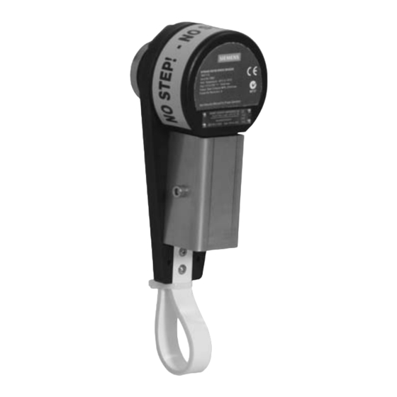
Page 7: Sitrans Ws100 Speed Sensor
• Long bearing life Eight pulses are generated for each rotation of the SITRANS WS100 shaft. These pulses are typically fed into a Milltronics belt scale integrator. The integrator interprets the pulses and uses them in the calculation of belt speed, flow rate, and material totalization. -
Page 8: Specifications
• WS100 standard: CE, C-TICK • WS100 IS: uses CE, ATEX and CSA approved Pepperl + Fuchs Proximity Switch and IS Switch Isolator (See Switch and Isolator Approvals on next page.) Page 4 SITRANS WS100 Speed Sensor – INSTRUCTION MANUAL 7ML19985LU01... - Page 9 Class I, Div. 1, Groups A,B,C, and D. Class II, Div. 1, Groups E,F, and G. Class III • CE Based on the ATEX rating of the NAMUR sensor and CSA approvals. 7ML19985LU01 SITRANS WS100 Speed Sensor – INSTRUCTION MANUAL Page 5...
-
Page 10: Installation
1.24" (31 mm) connector Ø 1.75" (44 mm) 8.75" 8.00" 2.00" (203 mm) (222 mm) (51 mm) Male shaft connector option 0.85" (22 mm) M12x1.75 male shaft connector 0.60" (15 mm) Page 6 SITRANS WS100 Speed Sensor – INSTRUCTION MANUAL 7ML19985LU01... -
Page 11: Mounting
Mounting The input shaft on the SITRANS WS100 is coupled to the rotating shaft on a belt-driven pulley with a tapped hole, and is externally supported. The unit’s arresting strap stops it from rotating with the shaft and can be fitted to any rigid support member close to the sensor. -
Page 12: Mounting To A Tail Pulley
(mounted off bearing) cable arrestor strap (mounted to restrainging bracket) "A" VIEW "A" - "A" Note: • When adjusting the belt take-up, ensure that the WS100 travels with the tail pulley bearing. Page 8 SITRANS WS100 Speed Sensor – INSTRUCTION MANUAL 7ML19985LU01... -
Page 13: Mounting To A Bend Or Snub Pulley
Mounting to a Bend or Snub Pulley conveyor conveyor stringer structure for arrestor strap SITRANS belt WS100 arrestor strap 7ML19985LU01 SITRANS WS100 Speed Sensor – INSTRUCTION MANUAL Page 9... -
Page 14: General Installation Steps
M12x1.75. If using magnetic connector, mount to shaft face, and go to step 3. WARNING: Exercise caution when completing step 1, and remain within specified tolerances. Thread the SITRANS WS100 onto the machine shaft using 16 mm or 5/8" open-ended wrench and releasable thread-locking adhesive (Loctite or similar). 25 mm (1") -
Page 15: Interconnection
² made with three-wire shielded, 0.324 mm (22 AWG) cable. To connect the SITRANS WS100 IS unit to the switch isolator, use two-wire shielded ² 0.324 mm (22 AWG) cable. Use the same cable to connect the switch isolator to the integrator. -
Page 16: Terminal Connections To Siemens Integrators
SIWAREX FTC (backplane (CI+) (CI-) bus) Notes: • N/C indicates the terminal is not normally connected • For terminal connections to older model Siemens integrators consult your local Siemens representative Page 12 SITRANS WS100 Speed Sensor – INSTRUCTION MANUAL 7ML19985LU01... -
Page 17: Maintenance
Wear on the bearings is detected by excess play or sound. If the bearings exhibit excess play or produce an unreasonably loud sound, the speed sensor should be returned to Siemens for repair. 7ML19985LU01 SITRANS WS100 Speed Sensor – INSTRUCTION MANUAL Page 13... - Page 18 Notes...
- Page 20 Siemens Milltronics Process Instruments Inc. Siemens Milltronics Process Instruments Inc. 2009 1954Technology Drive, P .O. Box 4225 Subject to change without prior notice Peterborough, ON, Canada K9J 7B1 *7ml19985LU01* Rev. 1.0 Tel: (705) 745-2431 Fax: (705) 741-0466 Email: techpubs.smpi@siemens.com...
Need help?
Do you have a question about the sitrans WS100 and is the answer not in the manual?
Questions and answers