Siemens SIWAREX WL200 Series Operating Instructions Manual
Load cell
Hide thumbs
Also See for SIWAREX WL200 Series:
- Operating instructions manual (98 pages) ,
- Operating instructions manual (104 pages)
Table of Contents
Advertisement
IWAREX WL200
Weighing systems
Load cells
SIWAREX WL200
Operating Instructions
07/2016
A5E02199611B-03
___________________
Introduction
___________________
Safety instructions
___________________
Description
___________________
Installing
___________________
Connecting
___________________
Commissioning
___________________
Service and maintenance
___________________
Error messages and
troubleshooting
___________________
Technical data
___________________
Dimension drawings
___________________
Ordering data
___________________
Appendix
1
2
3
4
5
6
7
8
9
10
11
A
Advertisement
Table of Contents

Related Manuals for Siemens SIWAREX WL200 Series


Summary of Contents for Siemens SIWAREX WL200 Series
- Page 1 ___________________ IWAREX WL200 Introduction ___________________ Safety instructions ___________________ Weighing systems Description ___________________ Installing Load cells SIWAREX WL200 ___________________ Connecting ___________________ Commissioning Operating Instructions ___________________ Service and maintenance ___________________ Error messages and troubleshooting ___________________ Technical data ___________________ Dimension drawings ___________________ Ordering data ___________________ Appendix 07/2016...
- Page 2 Note the following: WARNING Siemens products may only be used for the applications described in the catalog and in the relevant technical documentation. If products and components from other manufacturers are used, these must be recommended or approved by Siemens. Proper transport, storage, installation, assembly, commissioning, operation and maintenance are required to ensure that the products operate safely and without any problems.
-
Page 3: Table Of Contents
Table of contents Introduction ............................. 7 Purpose of this documentation ....................7 History ............................7 Checking the consignment ....................... 8 Transportation and storage ....................... 8 Notes on warranty ........................8 Safety instructions ........................... 9 Prerequisites for safe use ......................9 2.1.1 Laws and directives ........................ - Page 4 Table of contents 6.3.1.1 When is height compensation necessary? ................33 6.3.1.2 Procedure for height compensation ..................33 6.3.2 Initial commissioning ......................34 6.3.3 Corner load adjustment ......................34 6.3.3.1 When is corner load adjustment necessary? ................. 34 6.3.3.2 General procedure for corner load adjustment ..............35 6.3.3.3 Example for corner load adjustment ..................
- Page 5 Table of contents Dimension drawings ..........................69 10.1 SIWAREX WL260 SP-S AA ....................69 10.2 SIWAREX WL260 SP-S AB ....................70 10.3 SIWAREX WL260 SP-S AE ....................70 10.4 SIWAREX WL260 SP-S SA ....................71 10.5 SIWAREX WL260 SP-S SB ....................72 10.6 SIWAREX WL260 SP-S SC ....................
- Page 6 Table of contents SIWAREX WL200 Operating Instructions, 07/2016, A5E02199611B-03...
-
Page 7: Introduction
Introduction Purpose of this documentation These instructions contain all information required to commission and use the device. Read the instructions carefully prior to installation and commissioning. In order to use the device correctly, first review its principle of operation. The instructions are aimed at persons mechanically installing the device, connecting it electronically, configuring the parameters and commissioning it, as well as service and maintenance engineers. -
Page 8: Checking The Consignment
The sales contract contains all obligations on the part of Siemens as well as the complete and solely applicable warranty conditions. Any statements regarding device versions described in the manual do not create new warranties or modify the existing warranty. -
Page 9: Safety Instructions
Safety instructions Prerequisites for safe use This device left the factory in good working condition. In order to maintain this status and to ensure safe operation of the device, observe these instructions and all the specifications relevant to safety. Observe the information and symbols on the device. Do not remove any information or symbols from the device. -
Page 10: Improper Device Modifications
Due to the large number of possible applications, each detail of the described device versions for each possible scenario during commissioning, operation, maintenance or operation in systems cannot be considered in the instructions. If you need additional information not covered by these instructions, contact your local Siemens office or company representative. Note... - Page 11 Safety instructions 2.4 Use in hazardous areas WARNING Unsuitable device for the hazardous area Danger of explosion. • Only use equipment that is approved for use in the intended hazardous area and labelled accordingly. WARNING Loss of safety of device with type of protection "Intrinsic safety Ex i" If the device has already been operated in non-intrinsically safe circuits or the electrical specifications have not been observed, the safety of the device is no longer ensured for use in hazardous areas.
- Page 12 Safety instructions 2.4 Use in hazardous areas SIWAREX WL200 Operating Instructions, 07/2016, A5E02199611B-03...
-
Page 13: Description
Description Range of application SIWAREX load cells are used for measuring forces and weights statically and dynamically. You can use SIWAREX load cells for almost all applications in industrial weighing technology. Examples include: ● Container weighers, hopper scales or platform scales, ●... - Page 14 Description 3.2 Design and principle of operation Principle of operation The basic component in each case is a special type of spring body. The application of force elastically deforms the spring body. The ohmic resistance of the strain gauges changes as a result.
-
Page 15: Nameplate Layout
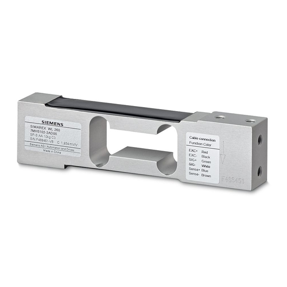
Description 3.3 Nameplate layout Nameplate layout Nameplate layout with general information ① Company logo ② Product group designation ③ Order number ④ Product designation ⑤ ⑥ Serial number ⑦ Rated characteristic value Cn of load cell ⑧ Manufacturer's address ⑨ Country of origin Figure 3-4 Example of nameplate layout with general information... - Page 16 Description 3.3 Nameplate layout Nameplate layout with approval information ① Ex marking of the customs union ② Types of protection of the customs union ③ Ex marking (ATEX) ④ Numbers of ATEX approvals ⑤ Type of protection according to ATEX ⑥...
-
Page 17: Installing
Installing Basic safety instructions Load cells are precision components and must therefore be handled carefully. Particular care must be taken during transport and installation. DANGER Danger to life from falling loads • Load cells are not machine components which have been constructed with the normal safety factors. -
Page 18: Procedure For Mounting The Device
Installing 4.2 Procedure for mounting the device NOTICE Damage to load cells through incorrect mounting • Provide indented claws or crane eyebolts on the load bearer to ensure that hoisting gear can be used safely. • Load cells must never be overloaded. Put the load carrier down slowly for this reason. With load cells of smaller rated loads in particular, there is a risk of stretching the load cell bodies when attaching force transfer devices, e.g. -
Page 19: Dismantling
Installing 4.3 Dismantling Dismantling For the disassembly of load cells, the same safety rules and requirements apply as for installation and assembly. 1. Disconnect all the supply voltages and auxiliary voltages. 2. Secure the load carrier against falling. 3. Use appropriate hoisting gear and tools. 4. - Page 20 Installing 4.3 Dismantling SIWAREX WL200 Operating Instructions, 07/2016, A5E02199611B-03...
-
Page 21: Connecting
Connecting Basic safety instructions WARNING Incorrect selection of type of protection Danger of explosion in areas subject to explosion hazard. This device is approved for several types of protection. 1. Decide in favor of one type of protection. 2. Connect the device in accordance with the selected type of protection. 3. -
Page 22: Connecting Principle
Connecting 5.2 Connecting principle Connecting principle Load cells can be equipped with connecting cables with four or six cores. WARNING Risk of explosion Please observe that in the case of shielded cables of intrinsically safe circuits in hazardous areas only one grounding is permissible. If grounding is to be on both sides an equipotential bonding conductor with at least 4 mm²... - Page 23 Connecting 5.2 Connecting principle Load cells with four-wire system Do not shorten or length connecting cables in the four-wire system, because the cable resistance is temperature compensated. When the length of the connecting cable is altered, the input and output resistances change. This change can be corrected by adjusting the scale, but temperature-dependent resistance changes are not compensated for the missing or additional length of cable.
-
Page 24: Connecting Up
Connecting 5.3 Connecting up Load cells with six-wire system For connecting cables in the six-wire system, the supply voltage is fed back to the weighing module as the reference voltage. Shortening or lengthening has no effect on the measuring result. Figure 5-2 Connecting principle for load cells with six-wire system Connecting up... - Page 25 Connecting 5.3 Connecting up Table 5- 1 Signal assignment for the load cell connecting cable Load cell Function/color of connecting cable EXC+ EXC- SIG+ SIG- Sense+ Sense- Shield SIWAREX WL260 Black Green White Blue Brown Trans- SP-S AA parent SIWAREX WL260 Black Green White...
- Page 26 Connecting 5.3 Connecting up Procedure Note Measurement errors Observe the warnings concerning extending or shortening the connecting cables in section → Lengthening and shortening the connecting cable (Page 31). If at all possible, do not shorten the connecting cables in a four-wire system. Note No calibration approval In scales requiring official calibration, the connecting cables for load cells in a four-wire...
-
Page 27: Commissioning
Commissioning Basic safety instructions WARNING Improper commissioning in hazardous areas Device failure or danger of explosion in hazardous areas. • Do not commission the device until it has been mounted completely and connected in accordance with the information in Technical data (Page 45). •... - Page 28 Commissioning 6.2 Application planning Parallel connection of load cells In weighing systems, one or more load cells are connected to a weighing module for evaluation of the measured signal. Several load cells of a scale are connected in parallel to a junction box to supply a joint output signal.
-
Page 29: Transverse Forces And Overload Protection
Commissioning 6.2 Application planning Grounding protection NOTICE Damaging of load cells Undesirable electrical currents can arise during welding or lightning. To protect the load cells against such currents, bridge the load cells using highly flexible grounding cables, see also Accessories (Page 98). 6.2.2 Transverse forces and overload protection Overloading of load cells... - Page 30 Commissioning 6.2 Application planning ● Persons supporting themselves on or climbing onto the scale ● Wind against the leeward side of a silo Dimensioning for overload When step changes in load cannot be excluded during measuring, for example, due to application of a load in free fall, you must take appropriate precautions to avoid damage to the load cell, e.g.
-
Page 31: Lengthening And Shortening The Connecting Cable
Commissioning 6.2 Application planning 6.2.3 Lengthening and shortening the connecting cable Load cells can be equipped with connecting cables with four or six cores. Note Measurement errors Connecting cables are only permitted to be extended using electro-magnetically compatible housings, such as the SIWAREX JB junction box. Single load cells If a scale is equipped with a single load cell, the scale can be directly connected to the weighing module if space permits. - Page 32 For connecting the junction box to the weighing module, to extend a load cell connecting cable or for cross-connection of two junction boxes, a shielded, six-core cable must be used, e.g. Li2Y2x0.75St+2x(2x0.34St)-CY Siemens Order No.: 7MH4 702-8AG or, for intrinsically safe Ex applications, 7MH4 702-8AF.
-
Page 33: Adjustment And Initial Commissioning
Commissioning 6.3 Adjustment and initial commissioning Adjustment and initial commissioning WARNING Missing type of protection and loss of approval If the load cell is not operated with an intrinsically safe power supply, the type of protection - intrinsically safe is no longer guaranteed and the intrinsically safe approval may be revoked. -
Page 34: Initial Commissioning
Commissioning 6.3 Adjustment and initial commissioning Height compensation of the load cells 1. Insert as many distance plates underneath the load cell with the lowest value as necessary to equalize the output voltages. 6.3.2 Initial commissioning 1. Align the load cell site horizontally and level over the complete area. 2. -
Page 35: General Procedure For Corner Load Adjustment
Commissioning 6.3 Adjustment and initial commissioning 6.3.3.2 General procedure for corner load adjustment The load cells are passive sensors: You should therefore follow the instructions in the manual for the weighing module primarily. When they are installed in hazardous areas, the instructions for the Ex i interface or for the Ex barrier must also be followed. - Page 36 Commissioning 6.3 Adjustment and initial commissioning Procedure 1. Measure the output resistances R of the load cells LC. Alternatively: Use the values from the corresponding data sheet. Example: Load cells Example values LC 1: 1004.52 Ω LC 2: 1003.64 Ω LC 3: 1010.70 Ω...
- Page 37 Commissioning 6.3 Adjustment and initial commissioning 4. Calculate the compensating resistance: Use the following formula: Determined compensation resistance, to be connected in the signal cable SIG+ Output resistance of the load cells; can also be measured under load Weight error: Differential value from the lowest weight value Test load;...
- Page 38 Commissioning 6.3 Adjustment and initial commissioning 5. Install the calculated resistances: Figure 6-4 Circuit diagram for corner load adjustment 6. Repeat the test. SIWAREX WL200 Operating Instructions, 07/2016, A5E02199611B-03...
-
Page 39: Service And Maintenance
Service and maintenance Basic safety instructions Servicing and maintenance of the load cells The load cells are in general maintenance free. Regular inspection and checking of the mechanisms for force transfer, oscillation limitation, lifting and overloading will however improve their reliability. The inspections should also be performed after serious environmental events such as storms, floods or earthquakes. -
Page 40: Disposal
Service and maintenance 7.4 Disposal Required forms ● Delivery note ● Return document (http://www.siemens.com/processinstrumentation/returngoodsnote) with the following information: – Product (item description) – Number of returned devices/replacement parts – Reason for returning the item(s) ● Decontamination declaration (http://www.siemens.com/sc/declarationofdecontamination) With this declaration you warrant "that the device/replacement part has been carefully cleaned and is free of residues. -
Page 41: Error Messages And Troubleshooting
Error messages and troubleshooting Repair Note Unnecessary costs for repairs Please only return faulty load cells to our repair center accompanied by an accurate description of the fault. This simplifies the diagnostics. Error messages Rated load exceeded If load cells are loaded beyond their rated load, this can result in an error message in the weighing module. -
Page 42: Checking The Load Cells
Error messages and troubleshooting 8.4 Checking the load cells Checking the load cells NOTICE Damaging of load cells Do not use an Ohmmeter to measure resistances that feeds a higher voltage into the load cell than is permitted in the specifications. Locate and check faulty load cells 1. -
Page 43: Measures In The Event Of Overloaded Load Cells
Error messages and troubleshooting 8.5 Measures in the event of overloaded load cells Measure the input and output resistance 1. Disconnect the load cell. 2. Measure the input voltage between EXC+ and EXC-. 3. Measure the output voltage between SIG+ and SIG-. The resistances must correspond to the values specified in the data sheet or in the specifications. - Page 44 Error messages and troubleshooting 8.5 Measures in the event of overloaded load cells SIWAREX WL200 Operating Instructions, 07/2016, A5E02199611B-03...
-
Page 45: Technical Data
Technical data Functional data 9.1.1 SIWAREX WL260 SP-S AA Table 9- 1 Technical specifications SIWAREX WL260 SP-S AA Variable Value Type series WL260 Designation SP-S AA Construction type Single-point load cell Possible applications Platform scales, small conveyor scales Rated load E 3;... -
Page 46: Siwarex Wl260 Sp-S Ab
Technical data 9.1 Functional data Variable Value Sensor material Aluminum Degree of protection according to EN 60 529 IP65 Maximum tightening torque of the fixing screws 15 ... 20 Nm Cable connection Six-core, shielded 9.1.2 SIWAREX WL260 SP-S AB Table 9- 2 Technical data SIWAREX WL260 SP-S AB Variable Value... -
Page 47: Siwarex Wl260 Sp-S Ae
Technical data 9.1 Functional data Variable Value Sensor material Aluminum Degree of protection according to EN 60 529 IP65 Maximum tightening torque of the fixing screws 35 ... 40 Nm Cable connection Six-core, shielded Type approval to OIML for SIWAREX WL260 SP-S AB available soon 9.1.3 SIWAREX WL260 SP-S AE Table 9- 3... -
Page 48: Siwarex Wl260 Sp-S Sa
Technical data 9.1 Functional data Variable Value Maximum tightening torque of the fixing screws 1.3 Nm Cable connection Four-core, shielded 0.4 m 9.1.4 SIWAREX WL260 SP-S SA Table 9- 4 Technical data SIWAREX WL260 SP-S SA Variable Value Type series WL260 Designation SP-S SA... -
Page 49: Siwarex Wl260 Sp-S Sb
Technical data 9.1 Functional data Variable Value Maximum tightening torque of the fixing screws for E = 5; 10; 20; 50; 100 kg 14 Nm for E = 200 kg 16 Nm Cable connection Six-core, shielded Type approval to OIML for SIWAREX WL260 SP-S SA available soon 9.1.5 SIWAREX WL260 SP-S SB Table 9- 5... -
Page 50: Siwarex Wl260 Sp-S Sc
Technical data 9.1 Functional data Variable Value Sensor material Stainless steel, mat. no. 1.4542 Degree of protection according to EN 60 529 IP68 Cable connection Six-core, shielded PU cable Maximum tightening torque of the fixing screws 10 Nm 9.1.6 SIWAREX WL260 SP-S SC Table 9- 6 Technical data SIWAREX WL260 SP-S SC Variable... -
Page 51: Siwarex Wl250 St-S Sa
Technical data 9.1 Functional data Variable Value Insulation resistance R ≥ 5000 MΩ (at 50 V DC) Rated temperature range B - 10 to + 40 °C Operating temperature range B - 35 to + 65 °C Storage temperature range B - 35 to + 65 °C Sensor material Stainless steel... -
Page 52: Siwarex Wl230 Bb-S Sa
Technical data 9.1 Functional data Variable Value Min. initial loading E 0 kg Maximum working load L 150% E Break load L 300% E Maximum lateral load L 100% E Rated measuring path h at E for E = 50; 100 kg 0.18 mm for E = 250;... -
Page 53: Siwarex Wl230 Sb-S Ca
Technical data 9.1 Functional data Variable Value Deviation F 0.017% C Creep error F 30 min 0.02 C Temperature coefficient Characteristic value T 0.014% C / 10 K Zero signal T 0.017% C / 10 K Min. initial loading E 0 kg Maximum working load L 150% E... - Page 54 Technical data 9.1 Functional data Variable Value Rated load E 100; 250; 500 kg 1; 2; 3; 5; 10 t Accuracy class according to OIML R60 C3; C4; C5 Max. scale interval n 3000; 4000; 5000 Min. scale interval V For E = 100;...
-
Page 55: Siwarex Wl230 Sb-S Sa
Technical data 9.1 Functional data Variable Value Maximum tightening torque for the fixing bolts for E = 100; 250; 500 kg, 1 t, 2 t 75 Nm for E = 3; 5 t 500 Nm for E = 10 t 750 Nm Cable connection Four-core, shielded... -
Page 56: Siwarex Wl270 Cp-S Sa
Technical data 9.1 Functional data Variable Value Rated measuring path h at E for E = 500 kg 0.13 mm for E = 1 t 0.21 mm for E = 2 t 0.29 mm for E = 5 t 0.38 mm Recommended supply voltage 5 to 12 V DC Rated characteristic value C... -
Page 57: Siwarex Wl270 Cp-S Sb
Technical data 9.1 Functional data Variable Value Temperature coefficient Characteristic value T 0.017% C / 10 K Zero signal T 0.023% C / 10 K Min. initial loading E 0 kg Maximum working load L 150% E Break load L 150% E Maximum lateral load L 75% E... -
Page 58: Siwarex Wl270 Cp-S Sc
Technical data 9.1 Functional data Variable Value Temperature coefficient Characteristic value T 0.017% C / 10 K Zero signal T 0.023% C / 10 K Min. initial loading E 0 kg Maximum working load L 150% E Break load L 300% E Maximum lateral load L 10% E... -
Page 59: Siwarex Wl270 K-S Ca
Technical data 9.1 Functional data Variable Value Min. initial loading E 0 kg Maximum working load L 150% E Break load L 300% E Maximum lateral load L 10% E Rated measuring path h at E 0.36 mm Recommended supply voltage 5 to 12 V DC Rated characteristic value C 2.0 ±... - Page 60 Technical data 9.1 Functional data Variable Values Characteristic value T ≤ ± 0.25% C / 5 °C ≤ ± 0.25% Cn / 5 °C Temperature coefficient • Zero signal T ≤ ± 0.25% C / 5 °C ≤ ± 0.25% Cn / 5 °C Min.
- Page 61 Technical data 9.1 Functional data Variable Values Combined error F ≤ ± 0.300% C ≤ ± 0.500 % C ≤ ± 5.000% C comb Min. initial loading E Hysteresis ≤ ± 0.300% C ≤ ± 0.500 % C ≤ ± 2.000% C Creep error F 30 min ≤...
-
Page 62: Siwarex Wl280 Rn-S Sa
Technical data 9.1 Functional data 9.1.15 SIWAREX WL280 RN-S SA Table 9- 16 Technical data SIWAREX WL280 RN-S SA Variable Value Type series WL280 Designation RN-S SA Construction type Ring torsion load cell Possible applications Container weighers, conveyor scales, platform scales, roller table scales Rated load E 0.06;... -
Page 63: Siwarex Wl290 Db-S Ca
Technical data 9.1 Functional data Variable Value Output resistance R for E = 0.06; 0.13; 0.28 t 1020 Ω ± 0.5 Ω for E = 0.5; 1; 2; 3.5; 5; 10 t 1025 Ω ± 25 Ω for E = 13 t 1000 Ω... -
Page 64: Electrical Specifications
Technical data 9.2 Electrical specifications Variable Value Combined error F ≤± 0.0230 % Cn for C3 comb ≤± 0.0175 % Cn for C4 Min. initial loading E 0 kg Maximum working load L 150% E Break load L 300% E Supply voltage U 5 ... -
Page 65: Approval To Oiml R60
Technical data 9.3 Approval to OIML R60 Zone 2 in protection type "ic" Connect the load cell only to devices that have been approved as at least "ic" certified (intrinsically safe) devices in category 3. Be sure to adhere to the permissible values. For SIWAREX WL280 RN-S SA Maximum values of the auxiliary power supply and signal circuit = 20 V DC... -
Page 66: Electromagnetic Compatibility
Technical data 9.4 Electromagnetic compatibility Electromagnetic compatibility To maintain the electromagnetic compatibility: ● Ensure that the cables are routed with electromagnetic compatibility, even within cabinets ● Lay the signal cable segregated from cables with voltages > 60 V or high currents ●... -
Page 67: Certificates And Approvals For Explosion Protection
Technical data 9.5 Certificates and approvals for explosion protection Certificates and approvals for explosion protection In hazardous areas, it is only permitted to use load cells and components with the appropriate ATEX approval. When connecting up the load cells in hazardous areas, the appropriate EC-type examination certificates and any supplements must be observed. - Page 68 Technical data 9.5 Certificates and approvals for explosion protection SIWAREX WL200 Operating Instructions, 07/2016, A5E02199611B-03...
-
Page 69: Dimension Drawings
Dimension drawings The dimensions in the dimension drawings are in mm. 10.1 SIWAREX WL260 SP-S AA Figure 10-1 SIWAREX WL260 SP-S AA dimension drawing Threaded holes Designation Thread Thread depth ① 15 mm SIWAREX WL200 Operating Instructions, 07/2016, A5E02199611B-03... -
Page 70: Siwarex Wl260 Sp-S Ab
Dimension drawings 10.2 SIWAREX WL260 SP-S AB 10.2 SIWAREX WL260 SP-S AB Figure 10-2 SIWAREX WL260 SP-S AB dimension drawing 8 threaded holes Designation Thread Thread depth ① 15 mm 10.3 SIWAREX WL260 SP-S AE Figure 10-3 Dimension drawing of SIWAREX WL260 SP-S AE SIWAREX WL200 Operating Instructions, 07/2016, A5E02199611B-03... -
Page 71: Siwarex Wl260 Sp-S Sa
Dimension drawings 10.4 SIWAREX WL260 SP-S SA 10.4 SIWAREX WL260 SP-S SA Figure 10-4 SIWAREX WL260 SP-S SA dimension drawing Threaded holes Designation Thread Thread depth Hole depth ① 15 mm 18 mm SIWAREX WL200 Operating Instructions, 07/2016, A5E02199611B-03... -
Page 72: Siwarex Wl260 Sp-S Sb
Dimension drawings 10.5 SIWAREX WL260 SP-S SB 10.5 SIWAREX WL260 SP-S SB Figure 10-5 Dimensional drawing SIWAREX WL260 SP-S SB Rated load in kg A in mm 18.5 18.5 18.5 23.5 Threaded holes M6x1, 8 mm deep SIWAREX WL200 Operating Instructions, 07/2016, A5E02199611B-03... -
Page 73: Siwarex Wl260 Sp-S Sc
Dimension drawings 10.6 SIWAREX WL260 SP-S SC 10.6 SIWAREX WL260 SP-S SC Figure 10-6 Dimension drawing SIWAREX WL260 SP-S SC 10 ... 50 kg Figure 10-7 Dimension drawing SIWAREX WL260 SP-S SC 100 ... 500 kg SIWAREX WL200 Operating Instructions, 07/2016, A5E02199611B-03... -
Page 74: Siwarex Wl250 St-S Sa
Dimension drawings 10.7 SIWAREX WL250 ST-S SA 10.7 SIWAREX WL250 ST-S SA Figure 10-8 SIWAREX WL250 ST-S SA dimension drawing Rated load Dimensions in mm 50 kg, 50.8 61.0 11.7 15.1 100 kg 250 kg, 50.8 61.0 18.0 21.4 500 kg 50.8 61.0 24.4... -
Page 75: Siwarex Wl230 Bb-S Sa
Dimension drawings 10.8 SIWAREX WL230 BB-S SA 10.8 SIWAREX WL230 BB-S SA Figure 10-9 SIWAREX WL230 BB-S SA dimension drawing Rated load d in mm D in mm H in mm 10; 20; 50; 100; 200 kg 500 kg 10,3 SIWAREX WL200 Operating Instructions, 07/2016, A5E02199611B-03... -
Page 76: Siwarex Wl230 Sb-S Ca
Dimension drawings 10.9 SIWAREX WL230 SB-S CA 10.9 SIWAREX WL230 SB-S CA Figure 10-10 Dimensional drawing SIWAREX WL230 SB-S CA Rated Dimensions in mm load Ø F 0.1 t ... 2.0 15.8 25.4 76.2 31.8 13.5 15.8 31.8 54.2 5.0 t 171.5 19.1 38.1... -
Page 77: Siwarex Wl230 Sb-S Sa
Dimension drawings 10.10 SIWAREX WL230 SB-S SA 10.10 SIWAREX WL230 SB-S SA Figure 10-11 SIWAREX WL230 SB-S SA dimension drawing Rated Dimensions in mm load 500 kg 25,4 20,5 1.0 t 25,4 20,5 2.0 t 25,4 20,5 5.0 t 38,1 20,5 30,2 SIWAREX WL200... -
Page 78: Siwarex Wl270 Cp-S Sa
Dimension drawings 10.11 SIWAREX WL270 CP-S SA 10.11 SIWAREX WL270 CP-S SA Figure 10-12 SIWAREX WL270 CP-S SA dimension drawing Rated load Dimensions in mm 10 t; 20 t; 30 t 50 t SIWAREX WL200 Operating Instructions, 07/2016, A5E02199611B-03... -
Page 79: Siwarex Wl270 Cp-S Sb
Dimension drawings 10.12 SIWAREX WL270 CP-S SB 10.12 SIWAREX WL270 CP-S SB Figure 10-13 SIWAREX WL270 CP-S SB dimension drawing SIWAREX WL200 Operating Instructions, 07/2016, A5E02199611B-03... -
Page 80: Siwarex Wl270 Cp-S Sc
Dimension drawings 10.13 SIWAREX WL270 CP-S SC 10.13 SIWAREX WL270 CP-S SC Figure 10-14 SIWAREX WL270 CP-S SC dimension drawing SIWAREX WL200 Operating Instructions, 07/2016, A5E02199611B-03... -
Page 81: Siwarex Wl270 K-S Ca
Dimension drawings 10.14 SIWAREX WL270 K-S CA 10.14 SIWAREX WL270 K-S CA Single Figure 10-15 Dimension drawing for SIWAREX WL270 K-S CA Rated load Dimensions in mm ∅d ∅D 1.3 to 2.8 t, 16.7 40.5 13 t 24.5 45.5 28 t 60 t 52.7 130 t... - Page 82 Dimension drawings 10.14 SIWAREX WL270 K-S CA With double bridge Figure 10-16 Dimension drawing SIWAREX WL270 K-S CA with double bridge Rated load Dimensions in mm ∅d ∅D 13 t 24.5 45.5 28 t 60 t 52.7 130 t 77.5 78.5 280 t 100.5...
-
Page 83: Siwarex Wl280 Rn-S Sa
Dimension drawings 10.15 SIWAREX WL280 RN-S SA 10.15 SIWAREX WL280 RN-S SA Dimension drawing for SIWAREX WL280 RN-S SA load cell for 60, 130, 280 kg The dimension drawing also contains the dimensions of the pressure piece. The pressure piece is included in the scope of delivery of the load cell. Figure 10-17 Dimension drawing for SIWAREX WL280 RN-S SA, rated load 60 kg, 130 kg, 280 kg SIWAREX WL200 Operating Instructions, 07/2016, A5E02199611B-03... - Page 84 Dimension drawings 10.15 SIWAREX WL280 RN-S SA Dimension drawing for SIWAREX WL280 RN-S SA load cell for 0.5, 1 t The dimension drawing also contains the dimensions of the pressure piece. The pressure piece is included in the scope of delivery of the load cell. Figure 10-18 Dimension drawing for SIWAREX WL280 RN-S SA, rated load 0.5 t, 1 t SIWAREX WL200 Operating Instructions, 07/2016, A5E02199611B-03...
- Page 85 Dimension drawings 10.15 SIWAREX WL280 RN-S SA Dimension drawing for SIWAREX WL280 RN-S SA load cell for 2, 3, 5 t The dimension drawing also contains the dimensions of the pressure piece. The pressure piece is included in the scope of delivery of the load cell. Figure 10-19 Dimension drawing for SIWAREX WL280 RN-S SA, rated load 2 t, 3 t, 5 t SIWAREX WL200 Operating Instructions, 07/2016, A5E02199611B-03...
- Page 86 Dimension drawings 10.15 SIWAREX WL280 RN-S SA Dimension drawing for SIWAREX WL280 RN-S SA load cell for 10 t The dimension drawing also contains the dimensions of the pressure piece. The pressure piece is included in the scope of delivery of the load cell. Figure 10-20 Dimension drawing for SIWAREX WL280 RN-S SA, rated load 10 t SIWAREX WL200 Operating Instructions, 07/2016, A5E02199611B-03...
- Page 87 Dimension drawings 10.15 SIWAREX WL280 RN-S SA Dimension drawing for SIWAREX WL280 RN-S SA load cell for 13 t Figure 10-21 Dimension drawing for SIWAREX WL280 RN-S SA, rated load 13 t SIWAREX WL200 Operating Instructions, 07/2016, A5E02199611B-03...
- Page 88 Dimension drawings 10.15 SIWAREX WL280 RN-S SA Dimension drawing for SIWAREX WL280 RN-S SA load cell for 28 t and 60 t Figure 10-22 Dimension drawing for SIWAREX WL280 RN-S SA, rated load 28 t and 60 t Rated load ∅...
-
Page 89: Siwarex Wl290 Db-S Ca
Dimension drawings 10.16 SIWAREX WL290 DB-S CA 10.16 SIWAREX WL290 DB-S CA Dimension drawing of the load cell SIWAREX WL290 DB-S CA for 2.3; 4.5; 9.1; 13.6; 18; 23; 27; 34; 45; 68 t Figure 10-23 Dimension drawing of WL290 DB-S CA Table 10- 1 Dimensions WL290 DB-S CA Rated... - Page 90 Dimension drawings 10.16 SIWAREX WL290 DB-S CA SIWAREX WL200 Operating Instructions, 07/2016, A5E02199611B-03...
-
Page 91: Ordering Data
Ordering data 11.1 Load cells SIWAREX WL230 Table 11- 1 Order Nos. SIWAREX WL230 BB-S SA SIWAREX WL230 BB-S SA Type series Designation Rated load Order number WL230 BB-S SA 10kg C3 10 kg 7MH5106-2AD00 WL230 BB-S SA 10kg C3 Ex 10 kg 7MH5106-2AD01 WL230... - Page 92 Ordering data 11.1 Load cells SIWAREX WL230 SB-S CA Type series Designation Rated load Order number WL230 SB-S CA 2t C3 7MH5121-4GD00 WL230 SB-S CA 2t C4 7MH5121-4GE00 WL230 SB-S CA 2t C5 7MH5121-4GF00 WL230 SB-S CA 3t C3 7MH5121-4KD00 WL230 SB-S CA 3t C4 7MH5121-4KE00...
- Page 93 Ordering data 11.1 Load cells SIWAREX WL 250 ST-S SA Type series Designation Rated load Order number WL250 ST-S SA 1t C3 7MH5105-4AD00 WL250 ST-S SA 1t C3 Ex 7MH5105-4AD01 WL250 ST-S SA 2.5t C3 2.5 t 7MH5105-4HD00 WL250 ST-S SA 2.5t C3 Ex 2.5 t 7MH5105-4HD01 WL250...
- Page 94 Ordering data 11.1 Load cells SIWAREX WL260 SP-S AB Type series Designation Rated load Order number WL260 SP-S AE 1.5 kg 1.5 kg WL260 SP-S AE 3 kg 3.0 kg Table 11- 8 Order Nos. SIWAREX WL260 SP-S SA SIWAREX WL260 SP-S SA Type series Designation Rated load...
- Page 95 Ordering data 11.1 Load cells SIWAREX WL260 SP-S SC Type series Designation Rated load Order number WL260 SP-S SC 400kg C3 400 kg 7MH5118-3MD00 WL260 SP-S SC 500kg C3 500 kg 7MH5118-3PD00 SIWAREX WL270 Table 11- 11 Order Nos. SIWAREX WL270 CP-S SA SIWAREX WL270 CP-S SA Type series Designation...
- Page 96 Ordering data 11.1 Load cells SIWAREX WL270 K-S CA Type series Designation Rated load Order number WL270 K-S CA 6t C3 Ex 7MH5114-4QL01 WL270 K-S CA 13t C3 13 t 7MH5114-5DL00 WL270 K-S CA 13t C3 Ex 13 t 7MH5114-5DL01 WL270 K-S CA 28t C3 28 t...
- Page 97 Ordering data 11.1 Load cells SIWAREX WL270 K-S CA with double bridge Type series Designation Rated load Order number WL270 K-S CA 350t 0.1% safe 350.0 t 7MH5114-6LL60 WL270 K-S CA 500t 0.1% safe 500.0 t 7MH5114-6PL60 Table 11- 17 Order Nos. SIWAREX WL270 K-S CA high temperature version with double bridge SIWAREX WL270 K-S CA high temperature version with double bridge Type series Designation...
-
Page 98: Accessories
Ordering data 11.2 Accessories SIWAREX WL280 RN-S SA Type series Designation Rated load Order number WL280 RN-S SA 13t C3 Ex 13 t 7MH5113-5DD01 WL280 RN-S SA 28t C3 28 t 7MH5113-5JD00 WL280 RN-S SA 28t C3 Ex 28 t 7MH5113-5JD01 WL280 RN-S SA 60t C3... -
Page 99: Appendix
In addition to our documentation collection, Siemens offers comprehensive support solutions ● Services & Support (http://www.siemens.com/automation/service&support) Contact If you have further questions about the device, please contact your local Siemens representative. ● Partner (http://www.automation.siemens.com/partner) In order to find the contact for your product, under 'All Products and Branches', select the path 'Automation Technology >... - Page 100 Appendix A.1 Technical support SIWAREX WL200 Operating Instructions, 07/2016, A5E02199611B-03...
-
Page 101: Index
Index Calibration approval, 31 Maintenance, 39 Certificates, 9 Connecting cable in four-wire system, 31 Connecting cable in six-wire system, 32 Corner load adjustment, 34 Ordering data Correct usage, (See improper device modifications) Accessories, 98 Customer Support Hotline, 99 Load cells, 91 Overload protection, 29 Design, 13 Dimension drawings, 69... - Page 102 Index Wheatstone bridge, 14 SIWAREX WL200 Operating Instructions, 07/2016, A5E02199611B-03...
Need help?
Do you have a question about the SIWAREX WL200 Series and is the answer not in the manual?
Questions and answers