Grandstream Networks UCM6202 User Manual
Ucm6200 series ip pbx
Hide thumbs
Also See for UCM6202:
- User manual (355 pages) ,
- Quick installation manual (22 pages) ,
- Security manual (32 pages)
Table of Contents
Advertisement
Quick Links
Advertisement
Table of Contents
Troubleshooting

Related Manuals for Grandstream Networks UCM6202


Summary of Contents for Grandstream Networks UCM6202
- Page 1 Grandstream Networks, Inc. UCM6200 Series IP PBX User Manual...
-
Page 2: Table Of Contents
PRODUCT OVERVIEW ................21 Technical Specifications ........................21 INSTALLATION ..................24 Equipment Packaging .......................... 24 Connect Your UCM6200 ........................24 Connect The UCM6202 ........................ 24 Connect The UCM6204 ........................ 25 Connect The UCM6208 ........................ 26 Safety Compliances ..........................27 Warranty .............................. 27 GETTING STARTED ................ - Page 3 Concurrent Multi-User Login ......................40 Operation Log ..........................40 Change Password ........................42 Change binding Email........................43 Network Settings ..........................44 Basic Settings ..........................44 DHCP Client List ........................... 49 802.1X ............................50 Static Routes ..........................52 Port Forwarding ..........................54 Open VPN .............................
- Page 4 Global Templates .......................... 99 Model configuration ........................... 101 Model templates ......................... 101 Model Update ..........................103 Device Configuration ......................... 104 Create New Device ........................104 Manage Devices ......................... 105 Sample Application ..........................112 EXTENSIONS ..................117 Create new user ..........................117 Create new SIP extension ......................
- Page 5 Inbound Route: Prepend Example ..................... 169 Inbound Route: Multiple Mode ....................170 FAX Intelligent Route ........................171 FAX with Two Media ........................172 Blacklist Configurations ......................172 CONFERENCE BRIDGE ................ 174 Conference Bridge Configurations ..................... 174 Join A Conference Call ....................... 176 Invite Other Parties to Join Conference..................
- Page 6 EXTENSION GROUPS ................207 Configure Extension Groups ......................207 Using Extension Groups ........................208 PICKUP GROUPS .................. 209 Configure Pickup Groups ........................209 Configure Pickup Feature Code ......................209 MUSIC ON HOLD ................... 211 FAX/T.38 ....................213 Configure Fax/T.38 ..........................213 Sample Configuration to Receive Fax from PSTN Line ..............
- Page 7 Feature Codes ........................... 240 Call Recording ........................... 244 Call Park ............................245 Park A Call ..........................245 Retrieve The Parked Call ......................246 Enable Spy ............................246 INTERNAL OPTIONS ................247 Internal Options/General ........................247 Internal Options/Jitter Buffer ......................249 Internal Options/RTP Settings ......................
- Page 8 PBX Status ............................269 Trunks ............................269 Extensions ..........................270 Queues ............................271 Conference Rooms ........................272 Interfaces Status ......................... 273 Parking Lot ..........................274 System Status ........................... 275 General ............................275 Network ............................276 Storage Usage ..........................276 Resource Usage ......................... 277 System Events ...........................
- Page 9 Network Status ........................... 304 Remote Access ..........................305 SSH Access ..........................305 EXPERIENCING THE UCM6200 SERIES IP PBX ......... 307 P a g e UMC6200 Series User Manual...
- Page 10 Table 1: Technical Specifications ........................ 21 Table 2: UCM6200 Equipment Packaging ....................24 Table 3: LCD Menu Options ........................29 Table 4: UCM6202/UCM6204 LED Indicators .................... 30 Table 5: UCM6208 LED Indicators ......................30 Table 6: User Management->Create New User ..................38 Table 7: Operation Log Column Header .....................
- Page 11 Table 39: IAX Extension Configuration Parameters->Features ..............125 Table 40: IAX Extension Configuration Parameters->Specific Time ............126 Table 41: FXS Extension Configuration Parameters->Basic Settings ............127 Table 42: FXS Extension Configuration Parameters->Media ..............128 Table 43: FXS Extension Configuration Parameters->Features ............... 129 Table 44: FXS Extension Configuration Parameters->Specific Time ............
- Page 12 Table 80: Internal Options/PIN Group ....................... 251 Table 81: IAX Settings/General ......................... 253 Table 82: IAX Settings/Registration ......................253 Table 83: IAX Settings/Static Defense ...................... 254 Table 84: SIP Settings/General ......................... 255 Table 85: SIP Settings/Misc ........................255 Table 86: SIP Settings/Session Timer ....................... 256 Table 87: SIP Settings/TCP and TLS ......................
- Page 13 Figure 30: UCM6204 Static Route Configuration..................54 Figure 31: UCM6200 Port Forwarding Configuration ................. 55 Figure 32: GXP2160 Web Access Using UCM6202 Port Forwarding ............56 Figure 33: Open VPN feature on the UCM6200 ..................57 Figure 34: Register Domain Name on noip.com ..................58 Figure 35: UCM6200 DDNS Setting ......................
- Page 14 Figure 39: LDAP Server Configurations ...................... 65 Figure 40: Default LDAP Phonebook DN ....................65 Figure 41: Default LDAP Phonebook Attributes ..................66 Figure 42: LDAP Server->LDAP Phonebook ....................66 Figure 43: Add LDAP Phonebook ....................... 67 Figure 44: Edit LDAP Phonebook ....................... 67 Figure 45: Import Phonebook........................
- Page 15 Figure 80: Edit Customize Device Settings ....................108 Figure 81: Add P Value in Customize Device Settings ................109 Figure 82: Modify Selected Devices - Same Model .................. 110 Figure 83: Modify Selected Devices - Different Models ................111 Figure 84: Device List in Zero Config ......................112 Figure 85: Zero Config Sample - Global Policy..................
- Page 16 Figure 121: Language Settings for Voice Prompt ..................188 Figure 122: Voice Prompt Package List ....................189 Figure 123: New Voice Prompt Language Added ..................189 Figure 124: Upload Single Voice Prompt for Entire Language Pack ............190 Figure 125: Voicemail Email Settings ....................... 194 Figure 126: Voicemail Group........................
- Page 17 Figure 162: Download Recording File from Recording Files Page ............245 Figure 163: Create New PIN Group ......................251 Figure 164: PIN members ......................... 252 Figure 165: Outbound PIN ........................252 Figure 166: CDR Record ........................... 252 Figure 167: FXS Ports Signaling Preference .................... 259 Figure 168: FXO Ports ACIM Settings ......................
- Page 18 Figure 203: Downloaded CDR File Sample - Source Channel and Dest Channel 2 ........ 287 Figure 204: CDR Statistics ........................288 Figure 205: CDR->Recording Files ......................289 Figure 206: Network Upgrade ........................291 Figure 207: Local Upgrade........................292 Figure 208: Upgrading Firmware Files ...................... 293 Figure 209: Reboot UCM6200 ........................
-
Page 19: Gnu Gpl Information
GNU GPL INFORMATION UCM6200 firmware contains third-party software licensed under the GNU General Public License (GPL). Grandstream uses software under the specific terms of the GPL. Please see the GNU General Public License (GPL) for the exact terms and conditions of the license. Grandstream GNU GPL related source code can be downloaded from Grandstream web site from: http://www.grandstream.com/support/faq/gnu-general-public-license/gnu-gpl-information-download P a g e... -
Page 20: Change Log
CHANGE LOG This section documents significant changes from previous versions of the UCM6200 user manuals. Only major new features or major document updates are listed here. Minor updates for corrections or editing are not documented here. Firmware Version 1.0.11.27 Added ability to sort extension status on web UI [Extensions] ... -
Page 21: Welcome
Reproduction or transmittal of the entire or any part, in any form or by any means, electronic or print, for any purpose without the express written permission of Grandstream Networks, Inc. is not permitted. P a g e UMC6200 Series User Manual... -
Page 22: Product Overview
UCM6202: 2 ports PSTN Line FXO Ports UCM6204: 4 ports UCM6208: 8 ports UCM6202/6204/6208: Dual Gigabit RJ45 ports with integrated PoE Plus Network Interfaces (IEEE 802.3at-2009) NAT Router Peripheral Ports USB, SD Power/Ready, Network, PSTN Line, USB, SD... - Page 23 Customizable Auto Attendant Up to 5 layers of IVR (Interactive Voice Response) UCM6202: Concurrent audio calls up to 30, concurrent WebRTC calls up to UCM6204: Concurrent audio calls up to 45, concurrent WebRTC calls up to Maximum Call Capacity ...
- Page 24 Call park, call forward, call transfer, DND, ring/hunt group, paging/intercom and Call Features FCC: Part 15 (CFR 47) Class B, Part 68 CE: EN55022 Class B, EN55024, EN61000-3-2, EN61000-3-3, EN60950-1, TBR21, RoHS Compliance A-TICK: AS/NZS CISPR 22 Class B, AS/NZS CISPR 24, AS/NZS 60950, AS/ACIF S002 and ITU-T K.21 (Basic Level) ...
-
Page 25: Installation
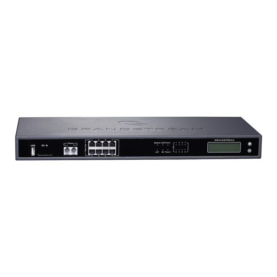
Main Case Yes (1) Power Adaptor Yes (1) Ethernet Cable Yes (1) Quick Installation Guide Yes (1) GPL License Yes (1) Connect Your UCM6200 Connect The UCM6202 Figure 1: UCM6202 Front View P a g e UMC6200 Series User Manual... -
Page 26: Connect The Ucm6204
2. Connect the other end of the Ethernet cable into the uplink port of an Ethernet switch/hub. 3. Connect the 12V DC power adapter into the 12V DC power jack on the back of the UCM6202. Insert the main plug of the power adapter into a surge-protected power outlet. -
Page 27: Connect The Ucm6208
Figure 4: UCM6204 Back View To set up the UCM6204, follow the steps below: 1. Connect one end of an RJ-45 Ethernet cable into the WAN port of the UCM6204. 2. Connect the other end of the Ethernet cable into the uplink port of an Ethernet switch/hub. 3. -
Page 28: Safety Compliances
8 x FXO Port LED Indicators USB Port Navigation Keys SD Card Slot 2 x FXS Port Figure 5: UCM6208 Front View Wan Port LAN Port Wan Port DC 12 V Reset Ground Figure 6: UCM6208 Back View Safety Compliances The UCM6200 series IP PBX complies with FCC/CE and various safety standards. -
Page 29: Getting Started
GETTING STARTED The UCM6200 series provides LCD interface, LED indication and web GUI configuration interface. The LCD displays hardware, software and network information. Users could also navigate in the LCD menu for device information and basic network configuration. The LED indication at the front of the device provides interface connection and activity status. -
Page 30: Table 3: Lcd Menu Options
Table 3: LCD Menu Options Critical Events View Events Other Events Hardware: Hardware version number Software: Software version number P/N: Part number Device Info WAN MAC: WAN side MAC address LAN MAC: LAN side MAC address ... -
Page 31: Use The Led Indicators
By default the SSH access is disabled. Use The LED Indicators The UCM6200 has LED indicators in the front to display connection status. The following table shows the status definitions. Table 4: UCM6202/UCM6204 LED Indicators LED Indicator LED Status Solid: Connected... -
Page 32: Figure 7: Ucm6204 Web Gui Login Page
Figure 7: UCM6204 Web GUI Login Page To access the Web GUI: 1. Connect the computer to the same network as the UCM6200. 2. Ensure the device is properly powered up and shows its IP address on the LCD. 3. Open a Web browser on the computer and enter the web GUI URL in the following format: http(s)://IP-Address:Port where the IP-Address is the IP address displayed on the UCM6200 LCD. -
Page 33: Setup Wizard
--------------------------------------------------------------------------------------------------------------------- ----------------------- Note: By default, the UCM6200 has "Redirect From Port 80" enabled. Therefore, if users type in the UCM6200 IP address in the web browser, the web page will be automatically redirected to the page using HTTPS and port 8089. For example, if the LCD shows 192.168.40.167, please enter 192.168.40.167 in your web browser and the web page will be redirected to: https://192.168.40.167:8089 The option "Redirect From Port 80"... -
Page 34: Web Gui Configurations
Figure 8: UCM6200 Setup Wizard During the wizard, the user can quit the setup wizard at any time to start over with manual configuration. At the last step of the wizard, the user will be provided with summary for review, before the configuration is loaded. -
Page 35: Web Gui Languages
Web GUI Languages Currently the UCM6200 series web GUI supports English, Simplified Chinese, Traditional Chinese, Spanish, French, Portuguese, Russian, Italian, Polish, German and etc. Users can select the displayed language in web GUI login page, or at the upper right of the web GUI after logging in. - Page 36 4. When your phone is registered with the extension, dial *97 to access the voicemail box. Enter the Voicemail Password once you hear "Password" voice prompt. 5. Once successfully logged in to the voicemail, you will be prompted with the Voice Mail Main menu. 6.
-
Page 37: System Settings
SYSTEM SETTINGS This section explains configurations for system-wide parameters on the UCM6200. System settings are under “Settings” tag on UCM6200 web GUI. System settings include User Management, Network Settings, Firewall, Change Password, LDAP server, HTTP server, Email settings, Time Settings, NTP Server, Recordings Storage and Login Timeout settings. -
Page 38: Create New Web Ui User
Super Admin can view operation logs generated by all users. By default, the user account “admin” is configured with “Super Admin” privilege and it’s the only user with “Super Admin” privilege. The User Name and Privilege level cannot be changed or deleted. -
Page 39: User Portal
Table 6: User Management->Create New User Configure a username to identify the user which will be required in web UI login. User Name Letters, digits and underscore are allowed in the user name. Configure a password for this user which will be required in web UI login. Letters, User Password digits and underscore are allowed. -
Page 40: Figure 13: Edit User Information By Super Admin
Figure 13: Edit User Information by Super Admin The following figure shows an example of login page using extension number 1000 as the username. Figure 14: User Portal Login After login, the web UI displays is shown as below. P a g e UMC6200 Series User Manual... -
Page 41: Concurrent Multi-User Login
Figure 15: User Portal Layout For the configuration parameter information in each page, please refer to [Table 6: User Management- for options in User Portal->Basic Information->User Information page; please refer >Create New User] for options in User Portal->Basic Information->Extension page; please refer to [EXTENSIONS] [CDR] for User Portal->Basic Information->CDR page. -
Page 42: Table 7: Operation Log Column Header
Figure 17: Operation Logs The operation log can be sorted and filtered for easy access. Click on the header of each column to sort. For example, clicking on "Date" will sort the logs according to operation date and time. Clicking on "Date" again will reverse the order. -
Page 43: Change Password
Figure 18: Operation Logs Filter The above figure shows an example that operations made by user “support” on device with IP 192.168.40.173 from 2014-11-01 00:00 to 2014-11-06 15:38 are filtered out and displayed. To delete operation logs, users can perform filtering first and then click on delete the filtered result of operation logs. -
Page 44: Change Binding Email
Figure 19 : Change Password Enter Old Password Enter the Old Password for UCM6200 Enter New Password Enter the New Password for UCM6200 Retype New Retype the New Password for UCM6200 Password Configure the Email address for UCM6200. In case login credential is lost, Email Email Address address is used to retrieve login credential Change binding Email... -
Page 45: Network Settings
UCM6202/UCM6204/UCM6208. Table 9: UCM6200 Network Settings->Basic Settings Select "Route", "Switch" or "Dual" mode on the network interface of UCM6200. The default setting is "Route". Route WAN port interface will be used for uplink connection. LAN port interface will be used to serve as router. - Page 46 DNS Server 2 Enter the DNS server 2 address for static IP settings. User Name Enter the user name to connect via PPPoE. Password Enter the password to connect via PPPoE. Layer 2 QoS 802.1Q/VLAN Assign the VLAN tag of the layer 2 QoS packets for WAN port. The default value is 0. Layer 2 QoS 802.1p Priority Assign the priority value of the layer 2 QoS packets for WAN port.
- Page 47 If "Dual" is selected as "Method", users will need assign the default interface to be LAN 1 Default (mapped to UCM6202 WAN port) or LAN 2 (mapped to UCM6202 LAN port) and then Interface configure network settings for LAN 1/LAN 2. The default interface is LAN 2.
-
Page 48: Figure 21: Ucm6200 Network Interface Method: Route
Figure 21: UCM6200 Network Interface Method: Route Method: Switch WAN port interface is used for uplink connection; LAN port interface is used as bridge for PC connection. P a g e UMC6200 Series User Manual... -
Page 49: Figure 22: Ucm6200 Network Interface Method: Switch
Figure 22: UCM6200 Network Interface Method: Switch Method: Dual Both WAN port and LAN port are used for uplink connection. Users will need assign LAN 1 or LAN 2 as the default interface in option "Default Interface" and configure "Gateway IP" if static IP is used for this interface. -
Page 50: Dhcp Client List
Figure 23: UCM6200 Network Interface Method: Dual DHCP Client List This feature can bind MAC to IP addresses on the LAN port when UCM6200 is set to Route mode. When devices receive IP addresses from LAN port, they will be listed on the webUI under “Settings > Network Settings >... -
Page 51: Figure 25: Add Mac Address Bind
Figure 25: Add MAC Address Bind User needs to set the device MAC address and the IP that will be bound to it (the IP address needs to be within the UCM6200 DHCP range). In order to bind a batch of listed MAC addresses, user needs to check first the MAC addresses to bind and click on . -
Page 52: Table 10: Ucm6200 Network Settings->802.1X
Figure 27: UCM6200 Using 802.1X as Client Figure 28: UCM6200 Using 802.1X EAP-MD5 The following table shows the configuration parameters for 802.1X on UCM6200. Identity and MD5 password are required for authentication, which should be provided by the network administrator obtained from the RADIUS server. -
Page 53: Static Routes
802.1X Certificate Select 802.1X certificate from local PC and then upload. 802.1X Client Select 802.1X client certificate from local PC and then upload. Certificate Static Routes The UCM6200 provides users static routing capability that allows the device to use manually configured routes, rather than information only from dynamic routing or gateway configured in the UCM6200 web GUI- >Network Settings->Basic Settings to forward traffic. -
Page 54: Figure 29: Ucm6204 Static Route Sample
Specify the network interface on the UCM6200 to reach the destination using the Interface static route. LAN interface is eth0; WAN interface is eth1. Static routes configuration can be reset from LCD menu->Network Menu. The following diagram shows a sample application of static route usage on UCM6204. Figure 29: UCM6204 Static Route Sample The network topology of the above diagram is as below: ... -
Page 55: Port Forwarding
Figure 30: UCM6204 Static Route Configuration Port Forwarding The UCM network interface supports router function which provides users the ability to do port forwarding. If LAN mode is set to "Route" under web GUI->Settings->Network Settings->Basic Settings page, port forwarding is available for configuration. The port forwarding configuration is under web GUI->Settings->Network Settings->Port Forwarding page. -
Page 56: Figure 31: Ucm6200 Port Forwarding Configuration
Select protocol type "UDP Only", "TCP Only" or "TCP/UDP" for the forwarding in Protocol Type the selected port. The default setting is "UDP Only". The following figures demonstrate a port forwarding example to provide phone’s web UI access to public side. -
Page 57: Open Vpn
Figure 32: GXP2160 Web Access Using UCM6202 Port Forwarding Open VPN Open VPN settings allow the users to configure UCM6200 to use VPN features Table 13: UCM6200 Settings -> Network Settings -> Open VPN Enable: Enable / Disable the open VPN feature. -
Page 58: Ddns Settings
Client Cert Upload a client certificate. This file will be renamed as ‘cliend.crt’ automatically. Upload a client private key. This file will be renamed as ‘client.key’ automatically. Client Key Figure 33: Open VPN feature on the UCM6200 DDNS Settings DDNS setting allows user to access UCM6200 via domain name instead of IP address. The UCM supports DDNS service from the following DDNS provider: ... -
Page 59: Figure 34: Register Domain Name On Noip.com
Here is an example of using noip.com for DDNS. 1. Register domain in DDNS service provider. Please note the UCM6200 needs to have public IP access. Figure 34: Register Domain Name on noip.com 2. On web UI->Settings->Network Settings->DDNS Settings, enable DDNS service and configure username, password and host name. -
Page 60: Firewall
Figure 36: Using Domain Name to Connect to UCM6200 Firewall The UCM6200 provides users firewall configurations to prevent certain malicious attack to the UCM6200 system. Users could configure to allow, restrict or reject specific traffic through the device for security and bandwidth purpose. -
Page 61: Table 14: Ucm6200 Firewall->Static Defense->Current Service
Table 14: UCM6200 Firewall->Static Defense->Current Service Port Process Type Protocol or Service 7777 Asterisk tcp/IPv4 Slapd tcp/IPv4 LDAP 2000 Asterisk tcp/IPv4 SCCP Dropbear tcp/IPv4 Lighthttpd tcp/IPv4 HTTP 8089 Lighthttpd tcp/IPv4 HTTPS Opentftpd udp/IPv4 TFTP 9090 Asterisk udp/IPv4 6060 zero_config udp/IPv4 UCM6200 zero_config service 5060 Asterisk... -
Page 62: Table 16: Firewall Rule Settings
Figure 37: Create New Firewall Rule Table 16: Firewall Rule Settings Rule Name Specify the Firewall rule name to identify the firewall rule. Select the action for the Firewall to perform. ACCEPT Action REJECT DROP Select the traffic type. ... -
Page 63: Dynamic Defense
Click on to edit the rule Click on to delete the rule Dynamic Defense Dynamic defense is supported on the UCM6200 series. It can blacklist hosts dynamically when the LAN mode is set to "Route" under web GUI->Settings->Network Settings->Basic Settings page. If enabled, the traffic coming into the UCM6200 can be monitored, which helps prevent massive connection attempts or brute force attacks to the device. -
Page 64: Fail2Ban
Figure 38: Configure Dynamic Defense Fail2ban Fail2Ban feature on the UCM6200 provides intrusion detection and prevention for authentication errors in SIP REGISTER, INVITE and SUBSCRIBE. Once the entry is detected within "Max Retry Duration", the UCM6200 will take action to forbid the host for certain period as defined in "Banned Duration". This feature helps prevent SIP brute force attacks to the PBX system. -
Page 65: Ldap Server
Configure the listening port number for the service. Currently only 5060 (for UDP) Protocol is supported. Configure the number of authentication failures during "Max Retry Duration" before MaxRetry the host is banned. The default setting is 10. Please make sure this option is properly configured as it will override the "MaxRetry"... -
Page 66: Ldap Server Configurations
LDAP Server Configurations The following figure shows the default LDAP server configurations on the UCM6200. Figure 39: LDAP Server Configurations The UCM6200 LDAP server supports anonymous access (read-only) by default. Therefore, the LDAP client doesn't have to configure username and password to access the phonebook directory. The "Root DN" and "Root Password"... -
Page 67: Ldap Phonebook
Figure 41: Default LDAP Phonebook Attributes LDAP Phonebook Users could use the default phonebook, edit the default phonebook, add new phonebook, import phonebook on the LDAP server as well as export phonebook from the LDAP server. The first phonebook with default phonebook dn "ou=pbx,dc=pbx,dc=com" displayed on the LDAP server page is for extensions in this PBX. -
Page 68: Figure 43: Add Ldap Phonebook
Add new phonebook A new sibling phonebook of the default PBX phonebook can be added by clicking on "Add" under "LDAP Phonebook" section. Figure 43: Add LDAP Phonebook Configure the "Phonebook Prefix" first. The "Phonebook DN" will be automatically filled in. For example, if configuring "Phonebook Prefix"... -
Page 69: Figure 45: Import Phonebook
Import phonebook from your computer to LDAP server Click on “Import Phonebook” and a dialog will prompt as shown in the figure below. Figure 45: Import Phonebook The file to be imported must be a CSV file with UTF-8 encoding. Users can open the CSV file with Notepad and save it with UTF-8 encoding. -
Page 70: Ldap Client Configurations
The sample phonebook CSV file in above picture will result in the following LDAP phonebook in the UCM6200. Figure 47: LDAP Phonebook After Import As the default LDAP phonebook with DN “ou=pbx,dc=pbx,dc=com” cannot be edited or deleted in LDAP phonebook section, users cannot import contacts with Phonebook DN field “pbx” if existed in the CSV file. -
Page 71: Figure 49: Ldap Client Configurations
Server Address: LDAP server IP address Base DN: dc=pbx,dc=com User Name: cn= “LDAP server login name”, dc=pbx, dc=com [matching LDAP server format] Password: “LDAP server login password” Filter: (|(CallerIDName=%)(AccountNumber=%)) Port: 389 The following figure gives a sample configuration for UCM6200 acting as a LDAP client. Figure 49: LDAP Client Configurations To configure Grandstream IP phones as the LDAP client, please refer to the following example: Server Address: The IP address or domain name of the UCM6200... -
Page 72: Http Server
The following figure shows the configuration information on a Grandstream GXP2200 to successfully use the LDAP server as configured in Figure 39: LDAP Server Configurations Figure 50: GXP2200 LDAP Phonebook Configuration HTTP Server The UCM6200 embedded web server responds to HTTP/HTTPS GET/POST requests. Embedded HTML pages allow the users to configure the PBX through a Web browser such as Microsoft IE, Mozilla Firefox and Google Chrome. -
Page 73: Email Settings
https://192.168.40.50:8089). Users could also change the access protocol and port as preferred under Web GUI->Settings->HTTP Server. Table 19: HTTP Server Settings Enable or disable redirect from port 80. On the PBX, the default access protocol is HTTPS and the default port number is 8089. When this option Redirect From Port 80 is enabled, the access using HTTP with Port 80 will be redirected to HTTPS with Port 8089. -
Page 74: Email Templates
when using type "Client". Display Name Specify the display name in the FROM header in the Email. Specify the sender's Email address. Sender For example, pbx@example.mycompany.com. The following figure shows a sample Email setting on the UCM6200, assuming the Email is using smtp.gmail.com as the SMTP server. -
Page 75: Time Settings
Figure 52: Email Templates To configure the email template, simply click the button under Options column, and edit the template as desired. Figure 53: Conference Schedule Template Time settings Auto time updating The current system time on the UCM6200 is displayed on the upper right of the web page. It can also be found under Web GUI->Status->System Status->General. -
Page 76: Table 21: Time Auto Updating
To configure the UCM6200 to update time automatically, go to Web GUI->Settings->Time Settings->Time Auto Updating. --------------------------------------------------------------------------------------------------------------------- ----------------------- Note: The configurations under Web GUI->Settings->Time Settings->Time Auto Updating page require reboot to take effect. Please consider configuring auto time updating related changes when setting up the UCM6200 for the first time to avoid service interrupt after installation and deployment in production. -
Page 77: Set Time Manually
M4.1.0,M11.1.0 The 1st number indicates Month: 1,2,3.., 12 (for Jan, Feb, .., Dec). The 2nd number indicates the nth iteration of the weekday: (1st Sunday, 3rd Tuesday…). Normally 1, 2, 3, 4 are used. If 5 is used, it means the last iteration of the weekday. -
Page 78: Table 22: Create New Office Time
Figure 55: Create New Office Time Table 22: Create New Office Time Start Time Configure the start time for office hour. End Time Configure the end time for office hour Week Select the work days in one week. Check this options to show advanced options. Once selected, please Show Advanced Options specify "Month"... -
Page 79: Holiday
Figure 56: Settings->Time Settings->Office Time Click on to edit the office time. Click on to delete the office time. Click on "Delete Selected Office Times" to delete multiple selected office times at once. Holiday On the UCM6200, the system administrator can define "holiday", which can be used to configure time condition for extension call forwarding schedule and inbound rule schedule. -
Page 80: Table 23: Create New Holiday
Table 23: Create New Holiday Name Specify the holiday name to identify this holiday. Holiday Memo Create a note for the holiday. Month Select the month for the holiday. Select the day for the holiday. Check this option to show advanced options. If selected, please specify Show Advanced Options the days as holiday in one week below. -
Page 81: Ntp Server
NTP Server The UCM6200 can be used as a NTP server for the NTP clients to synchronize their time with. To configure the UCM6200 as the NTP server, set "Enable NTP server" to "Yes" under web GUI->Settings->NTP Server. On the client side, point the NTP server address to the UCM6200 IP address or host name to use the UCM6200 as the NTP server. -
Page 82: Figure 60: Recordings Storage Prompt Information
Once “USB Disk” or “SD Card” is selected, click on “OK”. The user will be prompted to confirm to copy the local files to the external storage device. Figure 60: Recordings Storage Prompt Information Click on “OK” to continue. The users will be prompted a new dialog to select the categories for the files to be copied over. -
Page 83: Login Settings
Login Settings After the user logs in the UCM6200 web UI, the user will be automatically logged out after certain timeout, or he/she can be banned for a specific period if the login timeout is exceeded. Those values can be specified under UCM6200 web GUI->Settings->Login Timeout Settings page. -
Page 84: Google Service Settings Support
Google Service Settings Support UCM6200 now supports Google OAuth 2.0 authentication. This feature is used for supporting UCM6200 conference scheduling system. Once OAuth 2.0 is enabled, UCM6200 conference system can access Google calendar to schedule or update conference. Google Service Settings can be found under web GUI-> Settings-> Google Service Settings-> Google Service Settings. -
Page 85: Figure 64: Google Service->New Project
Figure 64: Google Service->New Project 2. Enable Calendar API from API Library. 3. Click “Credentials” on the left drop down menu to create new OAuth2.0 login credentials. Figure 65: Google Service->Create New Credential 4. Use the newly created login credential to fill in “OAuth2.0 Client ID” and “OAuth2.0 Client Secret”. 5. -
Page 86: Figure 66: Google Service->Oauth2.0 Login
Figure 66: Google Service->OAuth2.0 Login 6. Now UCM6200 is connected with Google Service. You can also configure the Status update, which refresh automatically your Google Calendar with the configured time (m). Note: Zero means disable. P a g e UMC6200 Series User Manual... -
Page 87: Provisioning
PROVISIONING Overview Grandstream SIP Devices can be configured via Web interface as well as via configuration file through TFTP/HTTP/HTTPS download. All Grandstream SIP devices support a proprietary binary format configuration file and XML format configuration file. The UCM6200 provides a Plug and Play mechanism to auto-provision the Grandstream SIP devices in a zero configuration manner by generating XML config file and having the phone to download it within LAN area. -
Page 88: Auto Provisioning Settings
Figure 67: Zero Config Configuration Architecture for End Point Device The configuration options in model layer and device layer have all the option in global layers already, i.e., the options in global layer is a subset of the options in model layer and device layer. If an option is set in all three layers with different values, the highest layer value will override the value in lower layer. -
Page 89: Figure 68: Ucm6200 Zero Config
Figure 68: UCM6200 Zero Config SIP SUBSCRIBE When the phone boots up, it sends out SUBSCRIBE to a multicast IP address in the LAN. The UCM6200 discovers it and then sends a NOTIFY with the XML config file URL in the message body. The phone will then use the path to download the config file generated in the UCM6200 and take the new configuration. -
Page 90: Table 24: Auto Provision Settings
Figure 69: Auto Provision Settings Table 24: Auto Provision Settings Enable or disable the zero config feature on the PBX. The default setting Enable Zero Config is enabled. By default, this is disabled. If disabled, when SIP device boots up, the UCM6200 will not send the SIP device the URL to download the config file and therefore the SIP device will not be automatically provisioned by the UCM6200. -
Page 91: Discovery
selecting extension to be provisioned via phone's LCD. The default setting is disabled. Click on the link "Pick Extension Segment" to specify the extension list to be sent to the device. The default range is 4000 to 4999. Pick Extension Pick Extension Segment Segment range can be defined in web UI->PBX->Internal Options- >General page->Extension Preference section: "Pick Extensions". -
Page 92: Global Configuration
Figure 70: Auto Discover The following figure shows a list of discovered phones. The MAC address, IP Address, Extension (if assigned), Version, Vendor, Model, Connection Status, Create Config, Options (Edit /Delete /Update /Reboot /Access Device WebGUI) are displayed in the list. Figure 71: Discovered Devices Global configuration Global policy... -
Page 93: Table 25: Global Policy Parameters->Localization
Web UI->PBX->Zero Config->Global Templates. Global Templates configuration has higher priority to Global Policy configuration. Global Policy can be accessed in web GUI->PBX->Zero Config->Global Policy page. On the top of the configuration table, users can select category in the "Options" dropdown list to quickly navigate to the category. -
Page 94: Table 26: Global Policy Parameters->Phone Settings
Configure the time display in 12-hour or 24-hour format on the SIP end device’s Time Format LCD. Configure the URL or IP address of the NTP server. The SIP end device may NTP Server obtain the date and time from the server. Time Zone Configure the time zone used on the SIP end device. -
Page 95: Table 27: Global Policy Parameters->Contact List
behind the same full cone NAT. The default setting is "No". Note: This parameter must be set to "No" for Direct IP Calling to work. General Settings Configure call progress tones including ring tone, dial tone, second dial tone, message waiting tone, ring back tone, call waiting tone, busy tone and reorder tone using the following syntax: f1=val, f2=val[, c=on1/ off1[- on2/ off2[- on3/ off3]]];... - Page 96 Select the protocol version for the phone to send the bind requests. The default Version value is 3. Specify the "name" attributes of each record which are returned in the LDAP search result. Example: Name Attribute cn sn description Specify the "number"...
-
Page 97: Table 28: Global Policy Parameters->Maintenance
Phonebook Download Configure the phonebook download interval (in Minute). If set to 0, automatic Interval download will be disabled. Valid range is 5 to 720. Remove manually-edited If set to "Yes", when XML phonebook is downloaded, the entries added entries on download manually will be automatically removed. -
Page 98: Table 29: Global Policy Parameters->Network Settings
Allow DHCP Option If DHCP option 43 or 66 is enabled on the LAN side, the TFTP server can be 43/66 redirected. If enabled, the endpoint device will automatically upgrade if a new firmware is detected. Users can select automatic upgrading by day, by week or by minute. ... -
Page 99: Table 30: Global Policy Parameters->Customization
Name for PPPoE. Advanced Setting Define the Layer 3 QoS parameter. This value is used for IP Precedence, Diff- Layer 3 QoS Serv or MPLS. Valid range is 0-63. Layer 2 QoS Tag Assign the VLAN Tag of the Layer 2 QoS packets. Valid range is 0 -4095. Layer 2 QoS Priority Assign the priority value of the Layer 2 QoS packets. -
Page 100: Global Templates
LCD screen wallpaper. Source Configure the location where wallpapers are stored. File If "URL" is selected as source, specify the URL of the wallpaper file. If "Local UCM Server" is selected as source, click to upload wallpaper file to the UCM6200. -
Page 101: Figure 73: Edit Global Template
Figure 73: Edit Global Template The added options will show in the list. Users can then enter or select value for each option to be used in the global template. On the left side of each added option, users can click on to remove this option from the template. -
Page 102: Model Configuration
Click on “Toggle Selected Template(s)” to toggle the status between enabled/disabled for the selected templates. Model configuration Model templates Model layer configuration allows users to apply model-specific configurations to different devices. Users could create/edit/delete a model template by accessing web GUI, page PBX->Zero Config->Model Templates. -
Page 103: Figure 74: Edit Model Template
The editing window for model template is shown in the following figure. In the “Options” field, enter the option name key word, the option that contains the key word will be listed. User could then select the option and click on “Add Option” to add it into the model template. Once added, the option will be shown in the list below. -
Page 104: Model Update
Click on Save when done. The model template will be displayed on web UI->PBX->Zero Config- >Model Templates page. Click on to delete the model template or click on “Delete Selected Templates” to delete multiple selected templates at once. ... -
Page 105: Device Configuration
In case the UCM6200 is placed in the private network and Internet access is restricted, users will not be able to get packages by downloading and installing from the remote server. Model template package can be manually uploaded from local device through web UI. Please contact Grandstream customer support if the model package is needed for manual uploading. -
Page 106: Manage Devices
Figure 77: Create New Device Manage Devices The device manually created or discovered from Auto Discover will be listed in the web UI->PBX->Zero Config->Zero Config page. Users can see the devices with their MAC address, IP address, vendor, model and etc. Figure 78: Manage Devices ... -
Page 107: Figure 79: Edit Device
A new dialog will be displayed for the users to configure “Basic” settings and “Advanced” settings. “Basic” settings have the same configurations as displayed when manually creating a new device, i.e., account, line key and MPK settings; “Advanced” settings allow users to configure more details in a five- level structure. - Page 108 (2) Global Templates Select a global template to be used for the device and click on to add. Multiple global templates can be selected and users can arrange the priority by adjusting orders via . All the selected global templates will take effect. If the same option exists on multiple selected global templates, the value in the template with higher priority will override the one in the template with lower priority.
-
Page 109: Figure 80: Edit Customize Device Settings
Figure 80: Edit Customize Device Settings Scroll down in the dialog to view and edit the device-specific options. If the users would like to add more options which are not in the pre-defined list, click on “Add New Field” to add a P value number and the value to the configuration. -
Page 110: Figure 81: Add P Value In Customize Device Settings
Figure 81: Add P Value in Customize Device Settings Select multiple devices that need to be modified and then click on batch modify devices. If selected devices are of the same model, the configuration dialog is like the following figure. Configurations in five levels are all available for users to modify. -
Page 111: Figure 82: Modify Selected Devices - Same Model
Figure 82: Modify Selected Devices - Same Model If selected devices are of different models, the configuration dialog is like the following figure. Click to view more devices of other models. Users are only allowed to make modifications in Global Templates and Global Policy level. -
Page 112: Figure 83: Modify Selected Devices - Different Models
Figure 83: Modify Selected Devices - Different Models --------------------------------------------------------------------------------------------------------------------- ----------------------- Note: Performing batch operation will override all the existing device configuration on the page. --------------------------------------------------------------------------------------------------------------------- ----------------------- After the above configurations, save the changes and go back to web UI->PBX->Zero Config->Zero Config page. -
Page 113: Sample Application
Figure 84: Device List in Zero Config In this web page, users can also click on “Reset All Extensions” to reset the extensions of all the devices. Sample Application Assuming in a small business office where there are 8 GXP2140 phones used by customer support and 1 GXV3275 phone used by customer support supervisor. -
Page 114: Figure 85: Zero Config Sample - Global Policy
Figure 85: Zero Config Sample - Global Policy 3. Go to web GUI->PBX->Zero Config->Model Templates, create a new model template “English Support Template” for GXP2140. Add option “Language” and set it to “English”. Then select the option “Default Model Template” to make it the default model template. 4. -
Page 115: Figure 86: Zero Config Sample - Device Preview 1
7. For each of the 5 phones used by English speaking customer support, in “Basic” settings select an available extension for account 1 and click on “Save”. Then click on “Advanced” settings tab to bring up the following dialog. Users will see the English support template is applied since this is the default model template. -
Page 116: Figure 87: Zero Config Sample - Device Preview 2
Figure 87: Zero Config Sample - Device Preview 2 “ ○ Select “Spanish Support Template” in Model Template”. The preview of the device settings is displayed on the right side and we can see the language is set to “Español” since Model Template has the higher priority for the option “Language”, which overrides the value configured in default model template. -
Page 117: Figure 88: Zero Config Sample - Device Preview 3
Figure 88: Zero Config Sample - Device Preview 3 10. Click on “Apply Changes” to apply saved changes. 11. On the web UI->PBX->Zero Config->Zero Config page, click on to send NOTIFY to trigger the device to download config file from UCM6200. Now all the 9 phones in the network will be provisioned with an unique extension registered on the UCM6200. -
Page 118: Extensions
EXTENSIONS Create new user Create new SIP extension To manually create new SIP user, go to Web GUI->PBX->Basic/Call Routes->Extensions. Click on "Create New User"->"Create New SIP Extension" and a new dialog window will show for users to fill in the extension information. -
Page 119: Table 33: Sip Extension Configuration Parameters->Basic Settings
The configuration parameters are as follows. Table 33: SIP Extension Configuration Parameters->Basic Settings General Extension The extension number associated with the user. Configure the CallerID Number that would be applied for outbound calls from this user. CallerID Number Note: The ability to manipulate your outbound Caller ID may be limited by your VoIP provider. -
Page 120: Table 34: Sip Extension Configuration Parameters->Media
Select the voice prompt language to be used for this extension. The default setting is "Default" which is the selected voice prompt language under web GUI->PBX- >Internal Options->Language. The dropdown list shows all the current available Language voice prompt languages on the UCM6200. To add more languages in the list, please download voice prompt package by selecting "Check Prompt List"... -
Page 121: Table 35: Sip Extension Configuration Parameters->Features
the received Fax will be sent to the Email address configured for this extension. If no Email address can be found for the user, the Fax will be sent to the default Email address configured in Fax setting page under web UI->PBX->Internal Options->Fax/T.38. - Page 122 Specific time can be configured on the bottom of the extension configuration dialog. Scroll down the add Time Condition for specific time. Office Time and Holiday could be configured on page Settings->Time Settings- >Office Time/Holiday page. Configure the Call Forward Busy target number. If not configured, the Call Forward Call Forward Busy Busy feature is deactivated.
-
Page 123: Table 36: Sip Extension Configuration Parameters->Specific Time
Other Settings Configure the number of seconds to ring the user before the call is forwarded to voicemail (voicemail is enabled) or hang up (voicemail is disabled). If not specified, the default ring timeout is 60 seconds on the UCM6200, which can be configured in the global ring timeout setting under web GUI->Internal Options->IVR Prompt: Ring Timeout General Preference. -
Page 124: Create New Iax Extension
Create New IAX Extension The UCM6200 supports Inter-Asterisk eXchange (IAX) protocol. IAX is used for transporting VoIP telephony sessions between servers and terminal devices. IAX is similar to SIP but also has its own characteristic. For more information, please refer to RFC 5465. To manually create new IAX user, go to Web GUI->PBX->Basic/Call Routes->Extensions. -
Page 125: Table 38: Iax Extension Configuration Parameters->Media
Email Address Fill in the Email address for the user. Voicemail will be sent to this Email address. Configure the password for user portal access. A random numeric password is User Password automatically generated. It is recommended to use the randomly generated password for security purpose. -
Page 126: Table 39: Iax Extension Configuration Parameters->Features
Table 39: IAX Extension Configuration Parameters->Features Call Transfer Configure the Call Forward Unconditional target number. If not configured, the Call Call Forward Forward Unconditional feature is deactivated. Unconditional The default setting is deactivated. Select time condition for Call Forward Unconditional. CFU takes effect only during the selected time condition. -
Page 127: Table 40: Iax Extension Configuration Parameters->Specific Time
Ring Simultaneously Enable this option to have an external number ring simultaneously along with the Ring extension. If a register trunk is used for outbound, the register number will be used to Simultaneously be displayed for the external number as caller ID number. Set the external number to be rang simultaneously. -
Page 128: Create New Fxs Extension
Create New FXS Extension The UCM6200 supports Foreign eXchange Subscriber (FXS) interface. FXS is used when user needs to connect analog phone lines or FAX machines to the UCM6200. To manually create new FXS user, go to Web GUI->PBX->Basic/Call Routes->Extensions. Click on "Create New User"->"Create New FXS Extension"... -
Page 129: Table 42: Fxs Extension Configuration Parameters->Media
Configure the password for user portal access. A random numeric password is User Password automatically generated. It is recommended to use the randomly generated password for security purpose. Select the voice prompt language to be used for this extension. The default setting is "Default"... -
Page 130: Table 43: Fxs Extension Configuration Parameters->Features
For FXS extension, there are three options available in Fax Mode. The default setting is “None”. None: Disable Fax. Fax Detect: Fax signal from the user/trunk during the call can be detected and the received Fax will be sent to the Email address configured for this extension. Fax Mode If no Email address can be found for the user, the Fax will be sent to the default Email address configured in Fax setting page under web UI->PBX->Internal... - Page 131 Select time condition for Call Forward Busy. The available time conditions are “Office Time”, “Out of Office Time”, “Holiday”, “Out of Holiday”, “Out of Office Time or Holiday” and “Specific”. Note: CFB Time “Specific” has higher priority to “Office Times” if there is a conflict in terms of time Condition period.
-
Page 132: Batch Add Extensions
Enable automatic recording for the calls using this extension. The default setting is Auto Record disabled. The recording files can be accessed under web GUI->CDR->Recording Files. If set to “Yes”, users can skip entering the password when making outbound calls. ... - Page 133 Enable Voicemail Enable Voicemail for the user. The default setting is "Yes". Configure the SIP/IAX password for the users. Three options are available to create password for the batch of extensions. User Random Password. A random secure password will be automatically generated. It is recommended SIP/IAX Password to use this password for security purpose.
- Page 134 NAT configuration or Firewall's support of SIP and RTP ports. The default setting is enabled. By default, the PBX will route the media steams from SIP endpoints through itself. If enabled, the PBX will attempt to negotiate with the endpoints to route the media Can Direct Media stream directly.
-
Page 135: Batch Add Iax Extensions
Enable T.38 Enable or disable T.38 UDPTL Support. UDPTL If enable “All”, users do not need to enter password when making an outbound call. If Skip Trunk Auth enable “Follow Me”, the user can dial out via follow me without password. Select audio and video codec for the extension. - Page 136 the default ring timeout is 60 seconds on the UCM6200, which can be configured in the global ring timeout setting under web GUI->Internal Options->IVR Prompt: General Preference. The valid range is between 5 seconds and 600 seconds. Note: If the end point also has a ring timeout configured, the actual ring timeout used is the shortest time set by either device.
-
Page 137: Search And Edit Extension
A Specific IP Address. Only the device on the specific IP address can register this extension. The default setting is "Allow All". If enable “All”, users do not need to enter password when making an outbound call. Skip Trunk Auth If enable “Follow Me”, the call can dial out via follow me without password. -
Page 138: Export Extensions
Reboot the user Click on to send NOTIFY reboot event to the device which has an UCM6200 extension already registered. To successfully reboot the user, "Zero Config" needs to be enabled on the UCM6200 web GUI->PBX->Zero Config->Auto Provisioning Settings. ... -
Page 139: Email To User
1. Export extension csv file from the UCM6200 by clicking on "Export Extensions" button. 2. Fill up the extension information you would like in the exported csv template. 3. Click on "Import Extensions" button. The following dialog will be prompted. Figure 92: Import Extensions 4. -
Page 140: Figure 93: Email To User - Prompt Information
Figure 93: Email To User - Prompt Information The user will receive Email including account registration information and LDAP configuration. A QR code is also generated for Mobile applications to scan it and get automatically provisioned. QR code provisioning is supported on Grandstream Softphone GS Wave Android application and iOS application. -
Page 141: Figure 95: Ldap Client Information And Qr Code
Figure 95: LDAP Client Information and QR Code P a g e UMC6200 Series User Manual... -
Page 142: Multiple Registrations Per Extension
Multiple Registrations Per Extension UCM6200 supports multiple registrations per extension so that users can use the same extension on devices in different locations. Figure 96: Multiple Registrations per Extension This feature can be enabled by configuring option “Concurrent Registrations” under web UI->PBX- >Basic/Call Routes->Edit Extension. -
Page 143: Sms Message Support
SMS message support The UCM6200 provides built-in SIP SMS message support. For SIP end devices such as Grandstream GXP or GXV phones that supports SIP message, after an UCM6200 account is registered on the end device, the user can send and receive SMS message. Please refer to the end device documentation on how to send and receive SMS message. -
Page 144: Trunks
Analog Trunk Configuration The analog trunk options are listed in the table below. Table 47: Analog Trunk Configuration Parameters Select the channel for the analog trunk. UCM6202: 2 channels Channels UCM6204: 4 channels UCM6208: 8 channels... - Page 145 When FXO port answers the call, FXS may send a Polarity Reversal. If this interval is Polarity on shorter than the value of “Polarity on Answer Delay”, the Polarity Reversal will be Answer Delay ignored. Otherwise, the FXO will onhook to disconnect the call. The default setting is 600ms.
- Page 146 Tone Settings Busy Detection is used to detect far end hangup or for detecting busy signal. The Busy Detection default setting is "Yes". If "Busy Detection" is enabled, users can specify the number of busy tones to be played before hanging up. The default setting is 2. Better results might be achieved if set to 4, 6 or even 8.
-
Page 147: Pstn Detection
PSTN Detection The UCM6200 provides PSTN detection function to help users detect the busy tone, Polarity Reversal and Current Disconnect by making a call from the PSTN line to another destination. The detecting call will be answered and up for about 1 minute. Once done, the detecting result will show and can be used for the UCM6200 settings. -
Page 148: Figure 100: Ucm6200 Pstn Detection
Figure 100: UCM6200 PSTN Detection If there are two FXO ports connected to PSTN lines, use the following settings for auto-detection. Detect Model: Auto Detect. Source Channel: The source channel to be detected. Destination Channel: The channel to help detecting. For example, the second FXO port. Destination Number: The number to be dialed for detecting. -
Page 149: Table 48: Pstn Detection For Analog Trunk
If there is only one FXO port connected to PSTN line, use the following settings for auto-detection. Figure 102: UCM6200 PSTN Detection: Semi-Auto Detect Detect Model: Semi-auto Detect. Source Channel: The source channel to be detected. Destination Number: The number to be dialed for detecting. This number could be a cell phone number or other PSTN number that can be reached from the source channel PSTN number. -
Page 150: Voip Trunks
manually. Please make sure one channel is connected to the UCM6200 and in idle status before starting the detection. During the detection, source channel will be used as caller and send the call to the configured Destination Number. Users will then need follow the prompts in web GUI to help finish the detection. -
Page 151: Table 49: Create New Sip Trunk
For VoIP trunk example, please refer to the document in the following link: http://www.grandstream.com/sites/default/files/Resources/ucm_to_ucm_peer_guide.pdf The VoIP trunk options are listed in the table below. Table 49: Create New SIP Trunk Select the VoIP trunk type. Type Peer SIP Trunk ... -
Page 152: Table 50: Sip Register Trunk Configuration Parameters
Select whether the trunk needs to register on the external server or not when Need Registration "Register SIP Trunk" type is selected. The default setting is No. Enter the username to register to the trunk from the provider when "Register SIP Username Trunk"... - Page 153 If the trunk has an assigned PSTN telephone number, this field should be set to "User=Phone". Then a "User=Phone" parameter will be attached to the Request- TEL URI Line and TO header in the SIP request to indicate the E.164 number. If set to "Enable", "Tel:"...
- Page 154 Outbound Proxy Select to enable outbound proxy in this trunk. The default setting is "No". Support When outbound proxy support is enabled, enter the IP address or URL of the Outbound Proxy outbound proxy. Configure where to get the destination ID of an incoming SIP call, from SIP DID Mode Request-line or To-header.
-
Page 155: Table 51: Sip Peer Trunk Configuration Parameters
Configure the maximum number of monitor structures which may be created for CC Max Monitors this device. In other words, this number tells how many callers may request CC services for a specific device at one time. The minimum value is 1. Table 51: SIP Peer Trunk Configuration Parameters Basic Settings Configure a unique label to identify this trunk when listed in outbound rules,... - Page 156 When making outgoing calls, the following rules are used to determine which CallerID will be used if they exist: The CallerID configured for the extension will be looked up first. If no CallerID configured for the extension, the CallerID configured for the trunk will be used.
-
Page 157: Table 52: Create New Iax Trunk
Fax Detect: Fax signal from the user/trunk during the call can be detected and the received Fax will be sent to the Email address configured for this extension. If no Email address can be found for the user, the Fax will be sent to the default Email address configured in Fax setting page under web UI- >PBX->Internal Options->Fax/T.38. -
Page 158: Table 53: Iax Register Trunk Configuration Parameters
Enter the username to register to the trunk from the provider when "Register IAX Username Trunk" type is selected. Enter the password to register to the trunk from the provider when "Register IAX Password Trunk" type is selected. Disable This Trunk If selected, the trunk will be disabled. -
Page 159: Table 54: Iax Peer Trunk Configuration Parameters
The default setting is 60 seconds. Maximum Number of The maximum number of concurrent calls using the trunk. The default settings 0, Call Lines which means no limited. Select Fax mode. The default setting is “None”. None: Disable Fax. ... -
Page 160: Direct Outward Dialing (Dod)
Qualify SIP message. If no response is received within the timeout, the device is considered offline. The default setting is 1000ms. When "Enable Qualify" option is set to "Yes", configure the interval (in seconds) of Qualify Frequency the SIP OPTIONS message sent to the device to check if the device is still online. The default setting is 60 seconds. -
Page 161: Figure 103: Dod Extension Selection
5. Select an extension from the "Available Extensions" list. Users have the option of selecting more than one extension. In this case, Company ABC would select the CEO's extension. After making the selection, click on the button to move the extension(s) to the "Selected Extensions" list. Figure 103: DOD extension selection 6. -
Page 162: Sla Station
SLA STATION The UCM6200 supports SLA that allows mapping the key with LED on a multi-line phone to different external lines. When there is an incoming call and the phone starts to ring, the LED on the key will flash in red and the call can be picked up by pressing this key. -
Page 163: Sample Configuration
Configure the time (in seconds) for delay before ringing the station when a call Ring Delay first coming in on the shared line. No delay is set by default. If set to 0, there will be no delay. This option defines the competence of the hold action for one particular trunk. If set to “open”, any station could hold a call on that trunk or resume one held Hold Access session;... -
Page 164: Figure 107: Analog Trunk With Sla Mode Enabled
Click on “Save”. The analog trunk will be listed with trunk mode “SLA”. Figure 107: Analog Trunk with SLA Mode Enabled 2. On the UCM6200, go to web UI->Basic/Call Routes->SLA Station page, click on “Create New SLA Station”. Please refer to section for the configuration parameters. -
Page 165: Call Routes
CALL ROUTES Outbound Routes Outbound Routes In the UCM6200, an outgoing calling rule pairs an extension pattern with a trunk used to dial the pattern. This allows different patterns to be dialed through different trunks (e.g., "Local" 7-digit dials through a FXO while "Long distance"... - Page 166 Password Configure the password for users to use this rule when making outbound calls. Call Duration Limit Enable to configure the maximum duration for the call using this outbound route. Maximum Call Configure the maximum duration of the call (in seconds). The default setting is 0, Duration which means no limit.
-
Page 167: Country Codes
Send This Call Through Trunk Use Trunk Select the trunk for this outbound rule. Allows the user to specify the number of digits that will be stripped from the beginning of the dialed string before the call is placed via the selected trunk. Example: Strip The users will dial 9 as the first digit of a long distance calls. -
Page 168: Inbound Routes
Figure 110: Country Codes Inbound Routes Inbound routes can be configured via Web GUI->PBX->Basic/Call Routes->Inbound Routes. Click on "Create New Inbound Rule" to add a new inbound route. Click on "Blacklist" to configure blacklist for all inbound routes. ... - Page 169 the caller ID and it is optional, if set it means only the extension with the specific caller ID is allowed to call in or call out. For example, patter '_2XXX/1234' means the only extension with the caller ID '1234' is allowed to use this rule. Prepend Trunk Name Prepend trunk name to display Configure the Alert-Info, when UCM6200 receives an INVITE request, the Alert-...
-
Page 170: Inbound Route: Prepend Example
Extension Conference Call Queue Ring Group Paging/Intercom Groups Voicemail Groups Fax Extension Dial by Name Time Condition Time Conditions Select the time condition for the inbound rule. Destination Select the destination for the inbound call during the specified time condition. Inbound Route: Prepend Example UCM6200 now allows user to prepend digits to an inbound DID pattern, with strip taking precedence over prepend. -
Page 171: Inbound Route: Multiple Mode
Figure 111: Inbound Route feature: Prepend The following example demonstrates the process, 1. If Trunk provides a DID pattern of 18005251163. 2. If Strip is set to 8, UCM6200 will strip the first 8 digits. 3. If Prepend is set to 2, UCM6200 will then prepend a 2 to the stripped number, now the number become 2163. -
Page 172: Fax Intelligent Route
Figure 112: Inbound Route - Multiple Mode When Multiple Mode is enabled for the inbound route, the user can configure a “Default Destination” and a “Mode 1” destination for this route. By default, the call coming into this inbound route will be routed to the default destination. -
Page 173: Fax With Two Media
FAX with Two Media The UCM6200 supports Fax re-invite with multiple codec negotiation. If a Fax re-invite contains both T.38 and PCMA/PCMU codec, UCM6200 will choose T.38 codec over PCMA/PCMU. Blacklist Configurations In the UCM6200, Blacklist is supported for all inbound routes. Users could enable the Blacklist feature and manage the Blacklist by clicking on "Blacklist". -
Page 174: Figure 114: Blacklist Csv File
Figure 114: Blacklist csv File ------------------------------------------------------------------------------------------------------------------- ------------------------- Note: Users could also add a number to the Blacklist or remove a number from the Blacklist by dialing the feature code for "Blacklist Add' (default: *40) and "Blacklist Remove" (default: *41) from an extension. The feature code can be configured under Web GUI->PBX->Internal Options->Feature Codes. -
Page 175: Conference Bridge
CONFERENCE BRIDGE The UCM6200 supports conference bridge allowing multiple bridges used at the same time: UCM6202/6204 supports up to 3 conference bridges allowing up to 25 simultaneous PSTN or IP participants. UCM6208 supports up to 6 conference bridges allowing up to 32 simultaneous PSTN or IP participants. - Page 176 bridge thus this field is invalid. The password has to be at least 4 characters. If enabled, conference participant could press the * key to access the conference Enable Caller Menu bridge menu. The default setting is "No". If enabled, the calls in this conference bridge will be recorded automatically in a .wav format file.
-
Page 177: Join A Conference Call
Join A Conference Call Users could dial the conference bridge extension to join the conference. If password is required, enter the password to join the conference as a normal user, or enter the admin password to join the conference as administrator. -
Page 178: During The Conference
--------------------------------------------------------------------------------------------------------------------- ----------------------- Note: Conference administrator can always invite other parties from the phone during the call by entering 0 or 1. To join a conference bridge as administrator, enter the admin password when joining the conference. A conference bridge can have multiple administrators. --------------------------------------------------------------------------------------------------------------------- ----------------------- During The Conference During the conference call, users can manage the conference from web GUI or IVR. -
Page 179: Record Conference
More options. 1: List all users currently in the conference call. 2: Kick all non-Administrator participants from the conference call. 3: Mute/Unmute all non-Administrator participants from the conference call. 4: Record the conference call. 8: Exit the caller menu and return to the conference. Conference User IVR Menu Mute/unmute yourself. -
Page 180: Figure 116: Conference Recording
Figure 116: Conference Recording P a g e UMC6200 Series User Manual... -
Page 181: Conference Schedule
CONFERENCE SCHEDULE Conference Schedule Configuration Conference Schedule can be found under UCM6200 web UI->PBX->Call Features->Conference Schedule. Users can create, edit, view and delete a Conference Schedule. Click on “Create New Conference Schedule” to add a new Conference Schedule. Click on the scheduled conference to edit or delete the event. - Page 182 Note: “LDAP Sync” must be enabled on the UCM6200 in order to view remote extensions here. Add extensions that are not in the list (both local and remote list). If the user wishes Special Extension to add the special extension, please match the pattern on the outbound route. Remote Conference Invite a remote conference.
-
Page 183: Figure 117: Conference Schedule
won’t require authentication. When Inviting Users via Trunk from Web Note: Please be aware of the potential security risks when turning on this option. Cleaner Options Cleaner Options Enable Conference If this option is enabled, conference schedules will be automatically cleaned as Schedules Cleaner configured. - Page 184 --------------------------------------------------------------------------------------------------------------------- ----------------------- Note: Please make sure that outbound route is properly configured for remote extensions to join the conference. Once Kick Time is reached, Conference Schedule is locked and cannot be modified. --------------------------------------------------------------------------------------------------------------------- ----------------------- P a g e UMC6200 Series User Manual...
-
Page 185: Ivr
Configure IVR IVR configurations can be accessed under the UCM6200 Web GUI->PBX->Call Features->IVR. Users could create, edit, view and delete an IVR. Click on "Create New IVR" to add a new IVR. Click on to edit the IVR configuration. ... - Page 186 Select an audio file to play as the welcome prompt for the IVR. Click on "Prompt" to Welcome Prompt add additional audio file under web GUI->Internal Options->IVR Prompt. Configure the timeout between digit entries. After the user enters a digit, the user needs to enter the next digit within the timeout.
-
Page 187: Create Custom Prompt
Dial by Name External Number Callback Create Custom Prompt To record new IVR prompt or upload IVR prompt to be used in IVR, click on “Prompt” next to the “Welcome Prompt” option and the users will be redirected to Custom Prompt page. Or users could go to Web GUI- >PBX->Internal Options->Custom Prompt page directly. -
Page 188: Upload Custom Prompt
Figure 119: Record New Custom Prompt Specify the IVR file name. Select the format (GSM or WAV) for the IVR prompt file to be recorded. Select the extension to receive the call from the UCM6200 to record the IVR prompt. ... -
Page 189: Language Settings For Voice Prompt
LANGUAGE SETTINGS FOR VOICE PROMPT The UCM6200 supports multiple languages in web GUI as well as system voice prompt. Currently, there are 16 languages supported in system voice prompt: English (United States), Arabic, Chinese, Dutch, English (United Kingdom), French, German, Greek, Hebrew, Italian, Polish, Portuguese, Russian, Spanish, Swedish and Turkish. -
Page 190: Figure 122: Voice Prompt Package List
Figure 122: Voice Prompt Package List Click on to download the language to the UCM6200. The installation will be automatically started once the downloading is finished. Figure 123: New Voice Prompt Language Added A new language option will be displayed after successfully installed. Users then could select it to apply in the UCM6200 system voice prompt or delete it from the UCM6200. -
Page 191: Customize Specific Prompt
Customize Specific Prompt On the UCM6200, if the user needs to replace some specific customized prompt, the user can upload a single specific customized prompt from web UI->PBX->Internal Options->Language instead of the entire language pack. Figure 124: Upload Single Voice Prompt for Entire Language Pack P a g e UMC6200 Series User Manual... -
Page 192: Voicemail
VOICEMAIL Configure Voicemail If the voicemail is enabled for UCM6200 extensions, the configurations of the voicemail can be globally set up and managed under Web GUI->PBX->Call Features->Voicemail. Table 62: Voicemail Settings Configure the maximum number of seconds for the voicemail greeting. The Max Greeting default setting is 60 seconds. -
Page 193: Access Voicemail
If enabled, a brief introduction (received time, received from, and etc) of each Play Envelope message will be played when accessed from the voicemail application. The default setting is "Yes". If enabled, UCM will play from the voice message left most recently; if disabled, Play from Last UCM will play from the earliest left voice message If enabled, users can review the message following the IVR before sending the... -
Page 194: Voicemail Email Settings
3 - Hear the message envelop 4 - Leave a message * - Return to the main menu 1 - Accept this recording 1 - Record your unavailable 2 - Listen to it message 3 - Re-record your message 1 - Accept this recording 2 - Record your busy message 2 - Listen to it 3 - Re-record your message... -
Page 195: Configure Voicemail Group
${VM_DATE}: The date and time when the message is left Figure 125: Voicemail Email Settings Click on "Load Default Settings" button to view the default template as an example. Configure Voicemail Group The UCM6200 supports voicemail group and all the extensions added in the group will receive the voicemail to the group extension. -
Page 196: Table 65: Voicemail Group Settings
Figure 126: Voicemail Group Table 65: Voicemail Group Settings Enter the Voicemail Group Extension. The voicemail messages left to this extension Extension will be forwarded to all the voicemail group members. Configure the Name to identify the voicemail group. Letters, digits, _ and - are Name allowed. -
Page 197: Ring Group
RING GROUP The UCM6200 supports ring group feature with different ring strategies applied to the ring group members. This section describes the ring group configuration on the UCM6200. Configure Ring Group Ring group settings can be accessed via Web GUI->PBX->Call Features->Ring Group. Figure 127: Ring Group ... - Page 198 Select the “Music On Hold” Class of this Ring Group, “Music On Hold” can be Music On Hold managed from the “Music On Hold” panel on the left. This option is to set a custom prompt for a ring group to announce to caller. Custom Prompt Click on ‘Prompt’, it will direct to the page PBX->Internal Options->Custom Prompt, where users could record new prompt or upload prompt files.
-
Page 199: Remote Extension In Ring Group
Figure 128: Ring Group Configuration Remote Extension in Ring Group Remote extensions from the peer trunk of a remote UCM6200 can be included in the ring group with local extension. An example of Ring Group with peer extensions is presented in the following: 1. -
Page 200: Figure 129: Sync Ldap Server Option
Figure 129: Sync LDAP Server option 3. In case if LDAP server doesn’t sync automatically, user can manually sync LDAP server. Under VoIP Trunks page, click sync button shown in the following figure to manually sync LDAP contacts from peer UCM6200. -
Page 201: Figure 131: Ring Group Remote Extension
4. Under Ring Groups setting page, click . Ring Groups can be found under web UI-> PBX-> Call Features-> Ring Groups. 5. If LDAP server is synced correctly, Available LDAP Numbers box will display available remote extensions that can be included in the current ring group. Please also make sure the extensions in the peer UCM6200 can be included into that UCM6200’s LDAP contact. -
Page 202: Paging And Intercom Group
PAGING AND INTERCOM GROUP Paging and Intercom Group can be used to make an announcement over the speaker on a group of phones. Targeted phones will answer immediately using speaker. The UCM6200 paging and intercom can be used via feature code to a single extension or a paging/intercom group. This sections describes the configuration of paging/intercom group under Web GUI->PBX->Call Features->Paging/Intercom. -
Page 203: Figure 133: Page/Intercom Group Settings
Click on to edit the paging/intercom group. Click on to delete the paging/intercom group. Click on "Paging/Intercom Group Settings" to edit Alert-Info Header. This header will be included in the SIP INVITE message sent to the callee in paging/intercom call. Figure 133: Page/Intercom Group Settings ... -
Page 204: Call Queue
CALL QUEUE The UCM6200 supports call queue by using static agents or dynamic agents. Call Queue system can accept more calls than the available agents. Incoming calls will be held until next representative is available in the system. This section describes the configuration of call queue under Web GUI->PBX->Call Features- >Call Queue. -
Page 205: Table 68: Call Queue Configuration Parameters
Table 68: Call Queue Configuration Parameters Extension Configure the call queue extension. Name Configure the call queue name to identify the call queue. Select the strategy for the call queue. Ring All Ring all available Agents simultaneously until one answers. ... - Page 206 Password default setting is disabled. Configure the number of seconds an agent will ring before the call goes to the Ring Time Out next agent. The default setting is 15 seconds. Configure the number of seconds before a new call can ring the queue after the Wrapup Time last call on the agent is completed.
-
Page 207: Figure 135: Agent Login Settings
Figure 135: Agent Login Settings For example, if the call queue extension is 6500, Agent Login Extension Postfix is * and Agent Logout Extension Postfix is **, users could dial 6500* to login to the call queue as dynamic agent and dial 6500** to logout from the call queue. -
Page 208: Extension Groups
EXTENSION GROUPS The UCM6200 extension group feature allows users to assign and categorize extensions in different groups to better manage the configurations on the UCM6200. For example, when configuring "Enable Filter on Source Caller ID", users could select a group instead of each person's extension to assign. This feature simplifies the configuration process and helps manage and categorize the extensions for business environment. -
Page 209: Using Extension Groups
Using Extension Groups Here is an example where the extension group can be used. Go to Web GUI->PBX->Basic/Call Routes- >Outbound Routes and select "Enable Filter on Source Caller ID". Both single extensions and extension groups will show up for users to select. Figure 137: Select Extension Group in Outbound Route P a g e UMC6200 Series User Manual... -
Page 210: Pickup Groups
PICKUP GROUPS The UCM6200 supports pickup group feature which allows users to pick up incoming calls for other extensions if they are in the same pickup group, by dialing "Pickup Extension" feature code (by default *8). Configure Pickup Groups Pickup groups can be configured via Web GUI->PBX->Call Features->Pickup Groups. ... -
Page 211: Figure 139: Edit Pickup Feature Code
Figure 139: Edit Pickup Feature Code P a g e UMC6200 Series User Manual... -
Page 212: Music On Hold
MUSIC ON HOLD Music On Hold settings can be accessed via Web GUI->PBX->Internal Options->Music On Hold. In this page, users could configure music on hold class and upload music files. The "default" Music On Hold class already has 5 audio files defined for users to use. Figure 140: Music On Hold Default Class ... - Page 213 Click on to select music file from local PC and click on to start uploading. The music file uploaded has to be 8 KHz Mono format with size smaller than 5M. Click on next to the sound file to delete it from the selected Music On Hold Class. ...
-
Page 214: Fax/T.38
FAX/T.38 The UCM6200 supports T.30/T.38 Fax and Fax Pass-through. It can convert the received Fax to PDF format and send it to the configured Email address. Fax/T.38 settings can be accessed via Web GUI->PBX- >Internal Options->FAX/T.38. The list of received Fax files will be displayed in the same web page for users to view, retrieve and delete. -
Page 215: Sample Configuration To Receive Fax From Pstn Line
sending the Fax to the users. The template variables are: ${CALLERIDNUM} : Caller ID Number ${CALLERIDNAME} : Caller ID Name ${RECEIVEEXTEN} : The extension to receive the Fax ${FAXPAGES} : Number of pages in the Fax ... -
Page 216: Figure 141: Configure Analog Trunk Without Fax Detection
Figure 141: Configure Analog Trunk without Fax Detection 5. Go to UCM6200 web GUI->PBX->Basic/Call Routes->Extensions page. 6. Create or edit the extension for FXS port. Analog Station: Select FXS port to be assigned to the extension. By default, it's set to "None". ... -
Page 217: Figure 143: Configure Extension For Fax Machine: Analog Settings
Figure 143: Configure Extension for Fax Machine: Analog Settings 7. Go to web GUI->PBX->Basic/Call Routes->Inbound Routes page. 8. Create an inbound route to use the Fax analog trunk. Select the created extension for Fax machine in step 4 as the default destination. Figure 144: Configure Inbound Rule for Fax P a g e UMC6200 Series User Manual... -
Page 218: Sample Configuration For Fax-To-Email
Now the Fax configuration is done. When there is an incoming Fax calling to the PSTN number for the FXO port, it will send the Fax to the Fax machine. Sample Configuration for Fax-To-Email The following instructions describe a sample configuration on how to use Fax-to-Email feature on the UCM6200. -
Page 219: Figure 146: Inbound Route To Fax Extension
Figure 146: Inbound Route to Fax Extension 5. Once successfully configured, the incoming Fax from external Fax machine to the PSTN line number will be converted to PDF file and sent to the Email address Faxtest@ucm6200mycompany.com as attachment. P a g e UMC6200 Series User Manual... -
Page 220: Asterisk Manager Interface (Restricted Access)
ASTERISK MANAGER INTERFACE (RESTRICTED ACCESS) The UCM6200 supports Asterisk Manager Interface (AMI) with restricted access. AMI allows a client program to connect to an Asterisk instance commands or read events over a TCP/IP stream. It’s particularly useful when the system admin tries to track the state of a telephony client inside Asterisk. User could configure AMI parameters on UCM6200 web GUI->PBX->Internal Options->AMI. -
Page 221: Busy Camp-On
BUSY CAMP-ON The UCM6200 supports busy camp-on/call completion feature that allows the PBX to camp on a called party and inform the caller as soon as the called party becomes available given the previous attempted call has failed. The configuration and instructions on how to use busy camp-on/call completion feature can be found in the following guide: http://www.grandstream.com/sites/default/files/Resources/ucm6100_busy_camp_on_guide.pdf P a g e... -
Page 222: Follow Me
FOLLOW ME Follow Me is a feature on the UCM6200 that allows users to direct calls to other phone numbers and have them ring all at once or one after the other. Calls can be directed to users’ home phone, office phone, mobile and etc. -
Page 223: Table 70: Follow Me Settings
Click on “Add Follow Me Number” to add local extensions or external numbers to be called after ringing the extension selected in the first step. Once created, it will be displayed on the follow me web page list. Click on to edit the Follow Me configuration. -
Page 224: Table 71: Follow Me Options
Table 71: Follow Me Options Playback Incoming If enabled, the PBX will playback the incoming status message before starting the Follow Me steps. Status Message If enabled, the PBX will record the caller’s name from the phone so it can be Record the Caller’s Name announced to the callee in each step. -
Page 225: One-Key Dial
ONE-KEY DIAL The UCM6200 supports One-Key Dial that allows users to call a certain destination by pressing one digit 0 to 9 on the keypad. This creates a system-wide speed dial access for all the extensions on the UCM6200. To enable One-Key Dial, on the UCM6200 web GUI, go to page PBX->Call Features->One-Key Dial. Figure 149: Configure One-Key Dial User should first decide a digit used for One-Key Dial and check the option “Enable Destination”... -
Page 226: Figure 150: One-Key Dial Destinations
Figure 150: One-Key Dial Destinations P a g e UMC6200 Series User Manual... -
Page 227: Disa
DISA In many situations the user will find the need to access his own IP PBX resources but he is not physically near one of his extensions. However, he does have access to his own cell phone. In this case we can use what is commonly known as DISA (Direct Inward System Access). - Page 228 "Local", "National" and "International" from the lowest level to the highest level. The default setting is "Internal". If the user tries to dial outbound calls after dialing into the DISA, the UCM6200 will compared the DISA's permission level with the outbound route's privilege level.
-
Page 229: Callback Feature
CALLBACK FEATURE Callback is mainly designed for users who often use their mobile phones to make long distance or international calls which may have high service charges. The callback feature provides an economic solution for reduce the cost from this. The callback feature works as follows: 1. - Page 230 destinations are available: DISA The caller can then enter the desired number to dial out via UCM6200 trunk. P a g e UMC6200 Series User Manual...
-
Page 231: Blf And Event List
BLF AND EVENT LIST The UCM6200 supports BLF monitoring for extensions, ring group, call queue, conference room and parking lot. For example, on the user's phone, configure the parking lot number 701 as the BLF monitored number. When there is a parked call on 701, the LED for this BLF key will light up in red, meaning a call is parked against this parking lot. -
Page 232: Figure 152: Create New Event List
enter the remote extensions under "Special Extensions" field. Manually enter the remote extensions in the peer/register trunk to be monitored Special Extensions in the event list. Valid format: 5000,5001,9000 Figure 152: Create New Event List Remote extension monitoring works on the UCM6200 via event list BLF, among Peer SIP trunks or Register SIP trunks (register to each other). - Page 233 -------------------------------------------------------------------------------------------------------------------------------------------- Note: To configure LDAP sync, please go to UCM6200 web GUI->PBX->Basic/Call Routes->VoIP Trunk. You will see "Sync LDAP Enable" option. Once enabled, please configure password information for the remote peer UCM6200 to connect to the local UCM6200. Additional information such as port number, LDAP outbound rule, LDAP Dialed Prefix will also be required.
-
Page 234: Dial By Name
DIAL BY NAME Dial by Name is a feature on the PBX that allows caller to search a person by first or last name via his/her phone's keypad. The administrator can define the Dial by Name directory including the desired extensions in the directory and the searching type by "first name"... -
Page 235: Figure 154: Dial By Name Group In Ivr Key Pressing Events
1. Group Name Enter the Group Name. This is to identify the Dial by Name group. The Dial by Name group can be used as the destination for inbound route and key pressing event for IVR. The group name defined here will show up in the destination list when configuring IVR and inbound route. -
Page 236: Figure 155: Dial By Name Group In Inbound Rule
Figure 155: Dial By Name Group In Inbound Rule 2. Extension Configure the direct dial extension for the Dial By Name group. 3. Available Extensions/Selected Extensions Select available extensions from the left side to the right side as the directory for the Dial By Name group. -
Page 237: Figure 156: Configure Extension First Name And Last Name
Figure 156: Configure Extension First Name and Last Name 4. Query Type Specify the query type. This defines how the caller will need to enter to search the directory. By First Name: enter the first 3 digits of the first name to search the directory. By Last Name: enter the first 3 digits of the last name to search the directory. -
Page 238: Active Calls And Monitor
ACTIVE CALLS AND MONITOR The active calls on the UCM6200 are displayed in web UI->Status->Active Calls page. Users can monitor the status, hang up the call as well as barge in the active calls in real time manner. Active Calls Status To view the status of active calls, navigate to web GUI->Status->Active Calls. -
Page 239: Hang Up Active Calls
Hang Up Active Calls To hang up an active call, click on icon in the active call dialog. Users can also click on to hang up all active calls. Call Monitor During an active call, click on icon and the monitor dialog will pop up. Figure 159: Configure to Monitor an Active Call In the “Monitor”... - Page 240 5. Click on “Add”. An INVITE will be sent to the monitor’s extension. The monitor can answer the call and start monitoring. If “Require Confirmation” is enabled, the user will be asked to confirm to monitor the call. Another way to monitor active calls is to dial the corresponding feature codes from an extension. Please refer to section for instructions.
-
Page 241: Call Features
CALL FEATURES The UCM6200 supports call recording, transfer, call forward, call park and other call features via feature code. This section lists all the feature codes in the UCM6200 and describes how to use the call features. Feature Codes Table 75: UCM6200 Feature Codes Feature Maps ... - Page 242 Default code: #72. Enter the code during active call to park the call. Options Call Park Disable Allow Caller: Enable the feature code on caller side only. Allow Callee: Enable the feature code on callee side only. Allow Both: Enable the feature code on both caller and callee.
- Page 243 Feature Misc Default Setting: 1000. Feature Code Digits Configure the maximum interval (in milliseconds) between the digits input Timeout to activate the feature code. Default Extension: 700. Call Park During an active call, initiate blind transfer and then enter this code to park the call.
- Page 244 Default Code: *80. Intercom Prefix To intercom an extension, enter the code followed by the extension number. Default Code: *40. Blacklist Add To add a number to blacklist for inbound route, dial *40 and follow the voice prompt to enter the number.
-
Page 245: Call Recording
This is the feature code to speak to one side of the call (for example, whisper Whisper Spy to employees to help them handle a call). Only one side will be able to hear from the monitor’s extension. The default setting is *55. This is the feature code to join in on the call to assist both parties. -
Page 246: Call Park
3. To stop the recording, enter the "Audio Mix Record" feature code (by default it's *3) followed by # or SEND again. Or the recording will be stopped once the call hangs up. 4. The recording file can be retrieved under Web GUI->Status->CDR. Click on to play the recording or click on to download the recording file. -
Page 247: Retrieve The Parked Call
Retrieve The Parked Call To retrieve the parked call, simply dial the parking lot number and the call will be established. If a parked call is not retrieved after the timeout, the original extension who parks the call will be called back. Enable Spy If “Enable Spy”... -
Page 248: Internal Options
INTERNAL OPTIONS This section describes internal options that haven't been mentioned in previous sections yet. The settings in this section can be applied globally to the UCM6200, including general configurations, jitter buffer, RTP settings, ports config and STUN monitor. The options can be accessed via Web GUI->PBX->Internal Options->... - Page 249 1234, 2345, and etc), or common digits pattern (such as 111222, 321321 and etc) are not allowed to be configured as password. 2. Password for extension registration, web GUI admin login, LDAP and LDAP sync requires alphanumeric characters containing at least two categories of the following, with a minimum length of 4 characters.
-
Page 250: Internal Options/Jitter Buffer
Conference Extensions: 6300-6399 Ring Group Extensions: 6400-6499 Queue Extensions: 6500-6599 Voicemail Group Extensions: 6600-6699 IVR Extensions: 7000-7100 Dial By Name Extensions: 7101-7199 Fax Extensions: 7200-8200 Internal Options/Jitter Buffer Table 77: Internal Options/Jitter Buffer SIP Jitter Buffer Select to enable jitter buffer on the sending side of the SIP channel. -
Page 251: Internal Options/Payload
RTP End Configure the RTP port ending address. The default setting is 20000. Configure to enable or disable strict RTP protection. If enabled, RTP packets that do not come from the source of the RTP stream will be dropped. The default Strict RTP setting is "Disable". -
Page 252: Internal Options/Pin Groups
H.263P Configure the payload type for H.263+. The default setting is 100 103. Configure the payload type for VP8. The default settings is 108. Internal Options/PIN Groups The UCM6200 supports pin group. Once this feature is configured, users can apply pin group to specific outbound routes. -
Page 253: Figure 164: Pin Members
Figure 164: PIN members Please note, if pin group is enabled on outbound route level, password, privilege level and enable filter on source caller ID will be disabled. Figure 165: Outbound PIN If pin group CDR is enabled, the call with pin group information will be displayed as part of CDR under Account Code field. -
Page 254: Iax Settings
IAX SETTINGS The UCM6200 IAX global settings can be accessed via Web GUI->PBX->IAX Settings. IAX Settings/General Table 81: IAX Settings/General Configure the port number that the IAX2 will be allowed to listen to. The default Bind Port setting is 4569. Configure the address that the IAX2 will be forced to bind to. -
Page 255: Iax Settings/Static Defense
If set to "yes", the connection will be terminated if ACK for the NEW message is Auto Kill not received within 2000ms. Users could also specify number (in milliseconds) in addition to "yes" and "no". The default setting is "yes". Authentication If enabled, authentication traffic in debugging will not show. -
Page 256: Sip Settings
SIP SETTINGS The UCM6200 SIP global settings can be accessed via Web GUI->PBX->SIP Settings. SIP Settings/General Table 84: SIP Settings/General Realm For Digest Configure the host name or domain name for the UCM6200. Realms MUST be Authentication globally unique according to RFC3261. The default setting is Grandstream. Bind UDP Port Configure the UDP port used for SIP. -
Page 257: Sip Settings/Session Timer
SIP Settings/Session Timer Table 86: SIP Settings/Session Timer Select the session timer mode. The default setting is "Accept". The options are: Originate Always request and run session timer. Session Timers Accept Run session timer only when requested by other UA. ... -
Page 258: Sip Settings/Nat
automatically. Note: The size of the uploaded ca file must be under 2MB. This is the Certificate file (*.pem format only) used for TLS connections. It contains private key for client and signed certificate for the server. This file will be renamed TLS Cert as "TLS.pem"... - Page 259 Configure the maximum duration (in seconds) of incoming registration and Registration/Subscript subscription allowed by the UCM6200. The default setting is 3600. ion Time Configure the minimum duration (in seconds) of incoming registration and Registration/Subscript subscription allowed by the UCM6200. The default setting is 60. ion Time Enable Relaxed DTMF Select to enable relaxed DTMF handling.
-
Page 260: Ports Config
PORTS CONFIG The analog hardware (FXS port and FXO port) on the UCM6200 will be listed in this page. Click on edit signaling preference for FXS port or configure ACIM settings for FXO port. Select "Loop Start" or "Kewl Start" for each FXS port. And then click on "Update" to save the change. Figure 167: FXS Ports Signaling Preference For FXO port, users could manually enter the ACIM settings by selecting the value from dropdown list for each port. - Page 261 Current, and AC Impedance as predefined for your country's analog line characteristics. The default setting is "United States of America (USA)". Select country to set the On Hook Speed, Ringer Impedance, Ringer Threshold, Current Limiting, TIP/RING voltage adjustment, Minimum Operational Loop FXS Opermode Current, and AC Impedance as predefined for your country's analog line characteristics.
-
Page 262: Value-Added Features
VALUE-ADDED FEATURES FAX Sending The UCM6200 supports sending Fax via web UI access. This feature can be found on web UI->PBX- >Value-added Features->Fax Sending page. In order to send fax, pre-setup for analog trunk and outbound route is required. Please refer to sections [Analog Trunks], [VOIP Trunks] [Outbound Routes]... -
Page 263: Announcements Center Settings
Figure 170: Announcements Center Announcements Center Settings Table 91: Announcements Center Settings Configure a name for the newly created Announcements Center to identify this Name announcement center. Enter a code number for the custom prompt. This code will be used in combination with the group number. -
Page 264: Group Settings
Group Settings Table 92: Group Settings Configure a name for the newly created group to identify the group. Name Configure the group number. The group number is used in combination with the code. For example, if group number is 666, and code is 55. The user can dial 55666 to send prompt 55 to all members in group 666. -
Page 265: Figure 172: Announcements Center Code Configuration
5. Click to create a new Announcement Center. 6. Give a name to the newly created Announcement Center. 7. Specify the code which will be used with group number to send the voice message to. 8. Select the message that will be used by the code from the Custom Prompt drop down menu. To create a new Prompt, please click “Prompt”... -
Page 266: Pms
UCM6200 support Hotel Property Management System PMS, including checkIn/checkout services, wakeup calls, room status, Do Not Disturb which provide an ease of management for hotel application, this feature can be found on web UI->PBX->PMS. Note: The PMS integration on UCM was made with HMobile for now, more PMS software can be supported in future releases. -
Page 267: Figure 174: Create New Room
Figure 174: Create New Room Click “Save” to create the new room, the fields above can be configured from the HMobile platform, once set the following screen will be shown: Figure 175: Room Status User can Create a Batch of rooms as well by clicking on , the following window will pop up: P a g e... -
Page 268: Wake Up Service
Figure 176: Add batch rooms Wake Up Service , the following window In order to create a New Wake up service, user can click on will pop up: Figure 177: Create New Wake Up Service Table 94: PMS Wake up Service Field Description Room Number... -
Page 269: Figure 178: Wakeup Call Executed
Action Status Show the status of the call: Programmed: the call is scheduled for the time set Cancelled: the call is canceled Executed: the wakeup call is made Type Single: The call will be made once on the specific time. ... -
Page 270: Status And Reporting
STATUS AND REPORTING PBX Status The UCM6200 monitors the status for Trunks, Extensions, Queues, Conference Rooms, Interfaces and Parking lot. It presents administrators the real time status in different sections under web GUI->Status- >PBX Status. Figure 179: Status->PBX Status Trunks Users could see all the configured trunk status in this section. -
Page 271: Extensions
SIP Peer trunk status: Unreachable: The hostname cannot be reached. Unmonitored: QUALIFY feature is not turned on to be monitored. Reachable: The hostname can be reached. SIP Register trunk status: Registered Unrecognized Trunk Trunks Display trunk name Display trunk Type: ... -
Page 272: Queues
Table 96: Extension Status Display extension number (including feature code). The color indicator has the following definitions. Green: Free Status Blue: Ringing Yellow: In Use Grey: Unavailable Display the extension number. Extension Name/Label First name and last name of the extension. Display message status for the extension. -
Page 273: Conference Rooms
Figure 182: Queue Status The current call status (caller ID, duration), agent status, service level, calls summary (completed/abandoned) are shown for the call queue. The agent status is defined as below. Table 97: Agent Status The agent is available/idle. The agent is ringing. The agent is talking/busy. -
Page 274: Interfaces Status
Figure 183: Conference Room Status Other operations are also available in conference room status section: Click on "Conference Rooms", the web page will redirect to conference room configuration page which can also be accessed via web GUI->PBX->Call Features->Conference. Click on to refresh the conference room status. -
Page 275: Parking Lot
LAN/WAN connected. LAN/WAN not configured. LAN/WAN disconnected. FXS/FXO connected. FXS/FXO waiting. FXS/FXO busy. FXS/FXO not configured. FXS/FXO disconnected. Other operations are also available in interface status section: Click on "Interfaces Status", the web page will redirect to ports configuration page which can also be accessed via web GUI->PBX->Internal Options->Ports Config. -
Page 276: System Status
Other operations are also available in parking lot status section: Click on "Parking Lot", the web page will redirect to feature codes page which can also be accessed via web GUI->PBX->Internal Options->Feature Codes. Click on to refresh the parking lot status. ... -
Page 277: Network
Network Under Web GUI->Status->System Status->Network, users could check the network information for the UCM6200. Please see details in the following table. Table 101: System Status->Network Status -> System Status -> Network MAC Address Global unique ID of device, in HEX format. The MAC address can be found on the label coming with original box and on the label located on the bottom of the device. -
Page 278: Resource Usage
Figure 186: System Status->Storage Usage Resource Usage When configuring and managing the UCM6200, users could access resource usage information to estimate the current usage and allocate the resources accordingly. Under web UI->Status->System Status- >Resource Usage, the current CPU usage and Memory usage are shown in the pie chart. Figure 187: System Status->Resource Usage P a g e UMC6200 Series User Manual... -
Page 279: System Events
System Events The UCM6200 can monitor important system events, log the alerts and send Email notifications to the system administrator. Alert Events List The system alert events list can be found under Web GUI->Status->System Events->Alert Events List. The following event are currently supported on the UCM6200 which will have alert and/or Email generated if occurred: Disk Usage External Disk Usage... -
Page 280: Figure 189: System Events->Alert Events Lists: External Disk Usage
Detect Cycle: The UCM6200 will perform the internal disk usage detection based on this cycle. Users can enter the number and then select second(s)/minute(s)/hour(s)/day(s) to configure the cycle. Alert Threshold: If the detected value exceeds the threshold (in percentage), the UCM6200 system will send the alert. -
Page 281: Alert Log
Figure 191: System Events->Alert Events Lists: System Reboot Detect Cycle: The UCM6200 will check the system reboot based on this cycle. Users can enter the number and then select second(s)/minute(s)/hour(s)/day(s) to configure the cycle. 5. System Crash Figure 192: System Events->Alert Events Lists: System Crash ... -
Page 282: Figure 193: System Events->Alert Log
Figure 193: System Events->Alert Log User could also filter alert logs by selecting a certain event category, type of alert log, and/or specifying a certain time period. The matching results will be displayed after clicking on . Alert logs are classified into two types by the system: 1. -
Page 283: Alert Contact
Alert Contact Users could add administrator's Email address under Web GUI->Status->System Events->Alert Contact to send the alert notification to. Up to 10 Email addresses can be added. CDR (Call Detail Record) is a data record generated by the PBX that contains attributes specific to a single instance of phone call handled by the PBX. -
Page 284: Figure 196: Call Report
Start Time Specify the start time to filter the CDR report. Click on the calendar icon on the right and the calendar will show for users to select the exact date and time. End Time Specify the end time to filter the CDR report. Click on the calendar icon on the right and the calendar will show for users to select the exact date and time. - Page 285 Call From Example format: "John Doe" 2000 Call To Example format: 2002 Call Time Format: 0:00:02 Talk Time Format: 0:00:00 Account Code Example format: Grandstream/Test Status Answered, Busy, No answer or Failed. Users could perform the following operations on the call report. ...
-
Page 286: Cdr Improvement
to delete the recording file (the call record entry will not be deleted). Figure 197: Call Report Entry with Audio Recording File Automatic Download CDR Records User could configure the UCM6200 to automatically download the CDR records and send the records to multiple Email recipients in a specific hour. -
Page 287: Downloaded Cdr File
Figure 199: CDR Report Figure 200: Detailed CDR Information Downloaded CDR File The downloaded CDR (.csv file) has different format from the web UI CDR. Here are some descriptions. Caller number, Callee number "Caller number": the caller ID. "Callee number": the callee ID. If the "Source Channel"... -
Page 288: Statistics
Figure 202: Downloaded CDR File Sample - Source Channel and Dest Channel 1 DAHDI means it is an analog call, FXO or FXS. For UCM6202, DAHDI/(1-2) are FXO ports, and DAHDI(3-4) are FXS ports. For UCM6204, DAHDI/(1-4) are FXO ports, and DAHDI(5-6) are FXS ports. -
Page 289: Recording Files
Figure 204: CDR Statistics Table 103: CDR Statistics Filter Criteria Select one of the following trunk type. Trunk Type SIP Calls PSTN Calls Call Type Select one or more in the following checkboxes. Inbound calls Outbound calls ... -
Page 290: Api Configuration
Figure 205: CDR->Recording Files Click on “Delete Selected Recording Files” to delete the recording files. Click on “Delete All Recording Files” to delete all recording files. Click on to download the recording file in .wav format. Click on to delete the recording file. - Page 291 Username Configure the Username for API Authentication. Password Configure the Password for API Authentication. Permitted Specify a list of IP addresses permitted by API. This creates an AIP-specific access control list. Multiple entries are allowed. For example, "192.168.5.20/255.255.255.255" denies access from all IP addresses except 192.168.5.20.
-
Page 292: Upgrading And Maintenance
UPGRADING AND MAINTENANCE Upgrading The UCM6200 can be upgraded to a new firmware version remotely or locally. This section describes how to upgrade your UCM6200 via network or local upload. Upgrading Via Network The UCM6200 can be upgraded via TFTP/HTTP/HTTPS by configuring the URL/IP Address for the TFTP/HTTP/HTTPS server and selecting a download method. -
Page 293: Upgrading Via Local Upload
Table 105: Network Upgrade Configuration Upgrade Via Allow users to choose the firmware upgrade method: TFTP, HTTP or HTTPS. Firmware Server Path Define the server path for the firmware server. Firmware File Prefix If configured, only the firmware with the matching encrypted prefix will be downloaded and flashed into the UCM6200. -
Page 294: Figure 208: Upgrading Firmware Files
Figure 208: Upgrading Firmware Files Wait until the upgrading process is successful and a window will be popped up in the Web GUI. Figure 209: Reboot UCM6200 Click on "OK" to reboot the UCM6200 and check the firmware version after it boots up. --------------------------------------------------------------------------------------------------------------------- ----------------------- Note: Please do not interrupt or power cycle the UCM6200 during upgrading process. -
Page 295: No Local Firmware Servers
No Local Firmware Servers Service providers should maintain their own firmware upgrade servers. For users who do not have TFTP/HTTP/HTTPS server, some free windows version TFTP servers are available for download from http://www.solarwinds.com/products/freetools/free_tftp_server.aspx http://tftpd32.jounin.net Please check our website at http://www.grandstream.com/support/firmware for latest firmware. -
Page 296: Figure 210: Create New Backup
Figure 210: Create New Backup 1. Choose the type(s) of files to be included in the backup. 2. Choose where to store the backup file: USB Disk, SD Card or Local. 3. Name the backup file. 4. Click on "Backup" to start backup. Once the backup is done, the list of the backups will be displayed with date and time in the web page. -
Page 297: Data Sync
option allows UCM to perform automatically backup on the user specified time. Regular backup file can only be stored in USB / SD card / SFTP server. User is allowed to set backup time from 0-23 and how frequent the backup will be performed. Figure 212: Local Backup Data Sync Besides local backup, users could backup the voice records/voice mails/CDR/FAX in a daily basis to a... -
Page 298: Restore Configuration From Backup File
Figure 213: Data Sync Table 106: Data Sync Configuration Enable Data Sync Enable the auto data sync function. The default setting is "No". Account Enter the Account name on the SFTP backup server. Password Enter the Password associate with the Account on the SFTP backup server. Server Address Enter the SFTP server address. -
Page 299: Cleaner
A list of previous configuration backups is displayed on the web page. Users could click on of the desired backup file and it will be restored to the UCM6200. If users have other backup files on PC to restore on the UCM6200, click on "Upload Backup File" first and select it from local PC to upload on the UCM6200. -
Page 300: Table 107: Cleaner Configuration
Figure 215: Cleaner Table 107: Cleaner Configuration Enable CDR Cleaner Enable the CDR Cleaner function. CDR Clean Time Enter 0-23 to specify the hour of the day to clean up CDR. Clean Interval Enter 1-30 to specify the day of the month to clean up CDR. Enable VR Cleaner Enter the Voice Records Cleaner function. -
Page 301: Reset And Reboot
--------------------------------------------------------------------------------------------------------------------- ----------------------- Note: Cleaner will delete data based on Recording Storage selection. If USB Disk is selected, Cleaner will only clean data in USB and local data will leave untouched. If Enable auto change is selected and USB disk is connected, Cleaner will only delete data in USB drive. -
Page 302: Troubleshooting
The default syslog level for all modules is "error", which is recommended in your UCM6200 settings because it can be helpful to locate the issues when errors happen. Some typical modules for UCM6200 functions are as follows and users can turn on "notic" and "verb" levels besides "error"... -
Page 303: Ip Ping
Figure 217: Ethernet Capture The output result is in .pcap format. Therefore, users could specify the capture filter as used in general network traffic capture tool (host, src, dst, net, protocol, port, port range) before starting capturing the trace. IP Ping Enter the target host in host name or IP address. -
Page 304: Traceroute
Traceroute Enter the target host in host name or IP address. Then press "Start" button. The output result will dynamically display in the window below. Figure 219: Traceroute Analog Record Trace Analog record trace can be used to troubleshoot analog trunk issue, for example, the UCM6200 user has caller ID issue for incoming call from Analog trunk. -
Page 305: Service Check
Figure 220: Troubleshooting Analog Trunks After capturing the trace, users can download it for basic analysis. Or you can contact Grandstream Technical support in the following link for further assistance if the issue is not resolved. http://www.grandstream.com/index.php/support Service Check Enable Service Check to periodically check UCM6200. Check Cycle is configurable in seconds and the default setting is 60 sec. -
Page 306: Remote Access
Figure 222: Network Status Remote Access SSH Access SSH switch now is available via web UI and LCD. User can enable or disable SSH access directly from web UI or LCD screen. For web SSH access, please log in UCM6200 web interface and go to Maintenance- >Remote Access->SSH Access. -
Page 307: Figure 223: Ssh Access
Figure 223: SSH Access P a g e UMC6200 Series User Manual... -
Page 308: Experiencing The Ucm6200 Series Ip Pbx
EXPERIENCING THE UCM6200 SERIES IP PBX Please visit our website: http://www.grandstream.com to receive the most up- to-date updates on firmware releases, additional features, FAQs, documentation and news on new products. We encourage you to browse our product related documentation, FAQs User and Developer Forum answers to your general questions.
Need help?
Do you have a question about the UCM6202 and is the answer not in the manual?
Questions and answers