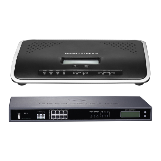
Grandstream Networks UCM6200 Series Basic Configuration Manual
Ip
Hide thumbs
Also See for UCM6200 Series:
- User manual (469 pages) ,
- Manual (28 pages) ,
- Configuring (13 pages)
Table of Contents
Advertisement
Quick Links
Download this manual
See also:
User Manual
Advertisement
Table of Contents

Related Manuals for Grandstream Networks UCM6200 Series


Summary of Contents for Grandstream Networks UCM6200 Series
- Page 1 Grandstream Networks, Inc. UCM6200 Basic Configuration Guide...
-
Page 2: Table Of Contents
OVERVIEW ........................4 SETUP GUIDE SCENARIO .................... 4 QUICK INSTALLATION ....................5 Connecting the UCM6200........................5 Access UCM6200 series Web Interface ....................5 CREATE USER EXTENSION ..................7 Configure Extension Range ........................7 Batch & Single User Creation ........................8 Steps on Adding Single User ...................... - Page 3 Table of Figures Figure 1: Typical UCM6200 Scenario ......................4 Figure 2: Quick Installation Guide for UCM6202 ..................5 Figure 3: Quick Installation Guide – Login Screen ..................6 Figure 4: Create User Extension – Extension Range ................... 7 Figure 5: Create User Extension – Extensions ..................... 8 Figure 6: Create User Extension –...
-
Page 4: Overview
OVERVIEW This document will provide instructions on how to set up a UCM6200 series from an out of the box state to a fully functional state. This includes design considerations, creating user extensions, provisioning endpoints with Zero-Config, conferencing, auto attendant configuration, analog/VoIP trunks, routing inbound/outbound calls and voicemail/fax to email setup. -
Page 5: Quick Installation
UCM6200 series LCD. This address is the WAN IP. If the computer is connected to the LAN side of the UCM6200 series, then users would browse to the default IP of the UCM6200 series which is 192.168.2.1. If connected successfully, the UCM6200 series login page will be displayed as shown below. -
Page 6: Figure 3: Quick Installation Guide - Login Screen
Figure 3: Quick Installation Guide – Login Screen P a g e UCM6200 Basic Configuration Guide... -
Page 7: Create User Extension
CREATE USER EXTENSION Configure Extension Range First part of configuring the UCM6200 series should be about planning for expansion. Here are some questions to think about when setting up extension ranges: • How many users are in the office? •... -
Page 8: Batch & Single User Creation
In the figure above, the user extension range is set with a starting extension of 100 and ending at 195. This allows up to 196 extensions to assign to users. We have also created a conference extension range from 196 to 199, which gives 4 conference bridges. -
Page 9: Steps On Adding Batch Of Users
Figure 6: Create User Extension – Create New User After clicking “Save” the Extensions page will display with the single SIP extension that was just created. Here the user has the ability to edit the extensions by clicking the at the right. Figure 7: Create User Extension –... -
Page 10: Figure 8: Create User Extension - Batch Add User
“Create Number”. In this tutorial, we will have a starting extension of 101 and have the UCM6200 series generate 5 extensions with a password randomly generated. This would create extensions 101, 102, 103, 104 and 105. -
Page 11: Figure 10: Create User Extension - Single And Batch Add Extensions Created
Figure 10: Create User Extension – Single and Batch Add Extensions Created For more details on Extension, parameters please see the UCM6200 series User Manual. P a g e UCM6200 Basic Configuration Guide... -
Page 12: Provisioning & Zero Config
GXP2135 with an IP address. By default, the IP assigned would be within the 192.168.2.X range. When the UCM6200 series offers an IP address to the phone it also offers DHCP Option 66, which provides the phone with a config server path that points to the UCM6200 series. All of Grandstream VoIP devices have Option 66 turned on by default and this is how the GXP2135 was discovered by the UCM6200. -
Page 13: Extension Assignment
The next screen provides details of the device and also allows a user to assign an extension. Since our GXP2135 is a 4-line phone, the UCM6200 series gives us the option to assign 4 extensions to the phone. Figure 12: Provisioning with Zero Config – Extension Assignment Check Account 1 and select the desired extension, then click “Save”. -
Page 14: Figure 13: Provisioning With Zero Config - Manually Assigned Extension
After assigning an extension, the phone may be rebooted in order to pick up the configuration file from the UCM6200 series. During this process, the phone will boot up, request for config file, download the config file, then reboot once more in order to apply the changes. -
Page 15: Conference Bridge
CONFERENCE BRIDGE The UCM6200 supports conference bridge allowing multiple bridges used at the same time: • UCM6202/6204 supports up to 3 conference bridges allowing up to 25 simultaneous PSTN or IP participants. • UCM6208 supports up to 6 conference bridges allowing up to 32 simultaneous PSTN or IP participants. conference bridge configurations... -
Page 16: Figure 16: Conference Bridge - New Conference Room Created
During a conference call, the admin can log in to the UCM6200 series and view the conference room status. This provides the admin with details on which conference room is active, who the participants are and the conference call’s current duration. -
Page 17: Ivr (Interactive Voice Response)
IVR (INTERACTIVE VOICE RESPONSE) Configure IVR IVR configuration can be accessed under the UCM6200 Web GUICall FeaturesIVR. Users could create, edit, view and delete an IVR. • Click on "Create New IVR" to add a new IVR. • Click on to edit the IVR configuration. -
Page 18: Figure 19: Ivr - Create New Ivr
For example, a caller reaches the IVR and the Welcome Prompt plays, “Thank you for calling Grandstream Networks. For support, please dial 0. For Sales, please dial 1.” Click on the drop down box for the first event, which is “Press 0” and select Extension. Another drop down box will appear and the user can then select an extension from the list. -
Page 19: Figure 20: Ivr - Key Pressing Events
Figure 20: IVR – Key Pressing Events 8. Click “Save” at the bottom and then click on “Apply Changes” at the top. To find out more options and parameter descriptions in regard to the IVR, please refer to the UCM6200 series User Manual. -
Page 20: Trunks
The UCM6200 series has built in FXO ports which allows it to pull in PSTN lines and provide analog trunk service. For this example, we will configure an analog line that is connected to FXO1. -
Page 21: Voip Trunks
Note: If there are reports of calls being dropped and lines are not disconnecting properly, this could mean that there are line settings mismatched. The UCM6200 series offers an auto detect feature that tests the line and provides the best possible settings. This option is called “PSTN Detection” which can be found under the Analog trunk configuration page. -
Page 22: Set Up Voip Trunk
There are 4 different type of VoIP trunks that can be configured. The types are Peered/Registered SIP trunk or Peered/Registered IAX trunk. This tutorial will demonstrate how to configure a SIP Registered Trunk. Set up VoIP Trunk 1. Click on “Create New SIP Trunk”. 2. -
Page 23: Figure 23: Voip Trunks - Advanced Settings
Figure 23: VoIP Trunks – Advanced Settings To verify if the SIP trunk is registered, the user may navigate to Web GUIStatus. Figure 24: Status – Trunks P a g e UCM6200 Basic Configuration Guide... -
Page 24: Call Routes
CALL ROUTES Outbound Routes In the UCM6200, an outgoing calling rule pairs an extension pattern with a trunk used to dial the pattern. This allows different patterns to be dialed through different trunks (e.g., "Local" 7-digit dials through a FXO while "Long distance"... -
Page 25: Inbound Routes
Figure 25: Routes – Create Outbound Route Inbound Routes In the UCM6200, an incoming calling rule allows for various inbound destinations. Users can route inbound calls by DID, to Extension, Voicemail, Conference Room, Queue, Ring Group, Page, Voicemail Group, FAX, DISA or IVR. -
Page 26: Set Up Inbound Route
Set up Inbound Route 1. Click on “Add”. 2. For “Trunks” select the SIP trunk that has been configured. (e.g. GS Trunk). 3. The DID pattern can be composed of two parts, divided by a ‘/’ character. The first part is used to specify the dialed number and the second part is used to specify the caller ID, which is optional.
Need help?
Do you have a question about the UCM6200 Series and is the answer not in the manual?
Questions and answers