Table of Contents
Advertisement
Quick Links
Advertisement
Table of Contents

Related Manuals for AnyTone THE OBLITERATOR OBLTR-8R


Summary of Contents for AnyTone THE OBLITERATOR OBLTR-8R
- Page 1 Package and Product Designed in U.S.A. MADE IN CHINA AnyToneTech.com Copyright © 2015 by AnyTone Tech All rights reserved. No part of this publication may be reproduced, distributed, or transmitted in any form or by any means without the permission of AnyTone Tech...
- Page 2 USER'S MANUAL...
- Page 4 THANK YOU FOR TRUSTING US WITH YOUR RADIO NEEDS ! transceivers provide you with reliable, clear, and precise communications. This transceiver includes innovative DSP (digital signal processing) technology - allowing for easy integration into all environments. We encourage you to read through the manual to understand the various functions to get the most from your handset.
- Page 5 THIS MANUAL IS FOR: OBLTR-8R OBLTR-8R Programming Software: OBLTR-8R_Setup_1.01.exe TERMN-8R TERMN-8R Programming Software: TERMN_8R_Setup_1.01.exe USB PROGRAMMING PRECAUTION When programming the transceiver, irst read from the radio, before modifying the frequencies data and settings. This will prevent errors caused from incompatible iles.
- Page 6 WARNINGS transceivers are intelligently designed with advanced technologies. The following tips are required to prevent voiding warranty and understanding the safety of transceiver usage. 1.Keep the transceiver and all accessories away from children. 2.Do not try to open or modify the transceiver without permission. Irresponsible operation of the transceiver may also cause damage.
-
Page 7: Table Of Contents
TABLE OF CONTENTS UNPACKING ........................................01 Supplied Accessories ..................................01 STANDARD ACCESSORIES/ADDITIONAL ACCESSORIES ....................02 Standard Accessories ..................................02 Additional Accessories ..................................02 USER MODE SETUP:AMATEUR OR COMMERCIAL RADIO ..................... 03 BATTERY INFORMATION ..................................05 Charging Operation ....................................05 Battery Charger Type ................................... - Page 8 TABLE OF CONTENTS Channel Adjusting ....................................15 Frequency Adjusting ..................................... 16 Receiving ........................................16 Transmitting ......................................17 Emergency Alarm ....................................17 Side Key [PF1] Setup and Use ............................... 17 Side Key [PF2] Setup and Use ............................... 19 Add a channel ......................................
- Page 9 TABLE OF CONTENTS NOAA .......................................... 33 MSK (Text) Signal Sending (TERMN-8R ONLY) ........................34 Function Menu Setup(OBLTR-8R) ..............................35 ..............................42 Function Menu Setup(TERMN-8R) ....................................49 Function Menu Setup ................................49 CTCSS/DCS Encode Setup ................................49 CTCSS/DCS Decode Setup CTCSS/DCS Encode/Decode Synchronous Setup ......................
- Page 10 TABLE OF CONTENTS Voice Operated Transmission (VOX) Setup ........................61 VOX Delay Setup ................................... 62 Automatic Power Off Time setup ............................62 DTMF Transmitting Time Setup ............................... 63 Squelch level setup ..................................63 Scanning Resume Time Setup ..............................64 Scan Speed .......................................
- Page 11 .................................... 102 Usage of Your Transceiver on Part 90 (Commercial) and Part 97 (Amateur) Frequencies ..... 102 Usage of Your Transceiver on Part 95 (Public) Frequencies .................. 102 LIMITED WARRANTY (UNITED STATES) ..........................103 ............................104 ANYTONE TECH’S LETTER TO YOU...
-
Page 12: Unpacking
UNPACKING Carefully unpack the transceiver. We recommend that you identify the items listed in the following table before discarding the packaging. If any items are missing or have been damaged during shipment, please contactyour dealer immediately. Supplied Accessories Item Number Quantity Antenna QA09UV1... -
Page 13: Standard Accessories/Additional Accessories
STANDARD ACCESSORIES/ADDITIONAL ACCESSORIES Standard Accessories Li-ion Battery Antenna* Battery Charger AC Adaptor Earphone QB-35L QBC-35L (12V/500mA) HS03 QA09UV1 155/435MHz QPS-01 *1.Note: For frequency band of antenna, please refer to label indicated in the bottom of the antenna. Belt Clip Instruction BC07 Manual Additional Accessories... -
Page 14: User Mode Setup:amateur Or Commercial Radio
USER MODE SETUP:AMATEUR OR COMMERCIAL RADIO The transceiver is a high performance amateur and professional radio with dual band, dual standby, dual display and other advanced features. According to your speciic application, you can set the radio to operate as an Amateur Transceiver or as a Professional (Commercial) Transceiver. There are 3 operating modes - and you can pick the mode best suited for your needs at anytime. - Page 15 USER MODE SETUP:AMATEUR OR COMMERCIAL RADIO channel operations are the same as described in frequency + channel mode. (As pic 2) This mode shows only frequency on the display. You can enter this VFO Mode(Frequency mode): " key, while you are in both FREQ and NAME Channel Modes. mode by simple pressing the "...
-
Page 16: Battery Information
BATTERY INFORMATION Charging Operation The battery is not charged at the factory, please charge it before your initial use. Charging the battery for the irst time or charging it after extended storage (more than 2 months) may not bring the battery to its maximum operating capacity after the irst charge.It may take repeating a full charge/discharge cycle for two or three times before the operating capacity reaches its maximum performance. -
Page 17: How To Charge
BATTERY INFORMATION ▲ Do not recharge the battery if it is already fully charged. This could shorten the life of the battery or damage the battery. ▲ Do not charge the battery or transceiver if it is damp or wet. Dry it before charging to avoid any danger. WARNING:When keys, ornamental chains, or other metals contact or short the battery terminals, the battery could cause a shock or injury. - Page 18 BATTERY INFORMATION NOTE: When charging a powered on transceiver equipped with battery, the LED will not turn to green to show the full charge status. Only when you turn off the transceiver, will the LED indicate normally. If the transceiver is powered on, it will continually consume energy. The charger cannot detect when the battery has been fully charged and will fail to indicate correctly.
-
Page 19: Charging Prompts Explained
BATTERY INFORMATION Charging Prompts Explained Self- examination: When plugging in your charger, the ORANGE light may lash for 1 second and go out. This means that the charger has passed its self-examination and it can charge the battery normally. If the light remains orange or the red light lashes this means the charger cannot pass its self-examination test and it will not charge the battery. -
Page 20: Installation & Connection Installing / Removing The Battery
INSTALLATION & CONNECTION Installing / Removing the Battery ■ Installing the Battery: Lay the battery to face the back of the radio. Press the bottom of the battery, the latch in the bottom of the transceiver lock will release. After hearing a "click", the battery has been locked. -
Page 21: Installing / Removing The Belt Clip
INSTALLATION & CONNECTION Installing / Removing the Belt Clip ■ Installing the Belt Clip: Place the belt clip to the grooves on the back of the transceiver, and then install the screws, turning clockwise. ■ Removing the Belt Clip: Remove the screws turning counterclockwise, allowing you to remove the belt clip. -
Page 22: Getting Acquainted Lcd Display
GETTING ACQUAINTED LCD Display On the LCD display screen, you will see various icons appear which stand for the functions you may have enabled. In order to thoroughly understand the icons and their meanings an overview is provided below: Frequency VOX Function Reverse Offset Frequency... - Page 23 GETTING ACQUAINTED DCIN...
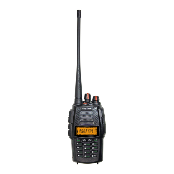
- Page 24 GETTING ACQUAINTED Antenna Channel Selector Knob Power / Volume Knob Rotate it clockwise to turn on the transceiver, rotate it counterclockwise until you hear the "click" to turn off the transceiver. When the transceiver is powered on, turn the knob clockwise to increase volume, or turn the knob counterclockwise to reduce the volume.
-
Page 25: Basic Operations
BASIC OPERATIONS Turn the Radio On & OFF When the radio is off turn [POWER]/ [VOLUME] clockwise to turn on the transceiver. When the radio is on,turn [POWER]/ [VOLUME] counterclockwise to turn off the transceiver. Adjusting Volume When the radio is on, turn [POWER] / [VOLUME] to adjust volume. The volume increases when you turn the knob clockwise and decreases when you turn the knob counterclockwise. -
Page 26: Switch Between Main Band And Sub Band
BASIC OPERATIONS Switch between Main band and Sub band While in standby press key to switch between Main band and Sub band. The Display Arrow will point to the current operating channel. Switch between Channel mode and VFO mode While in standby, press key to set the selected band into channel mode or frequency mode(VFO). -
Page 27: Frequency Adjusting
BASIC OPERATIONS Frequency Adjusting When the transceiver is in VFO frequency mode or is in FM radio frequency mode, rotate the channel knob to adjust the frequency, or you can input the frequency by the keypad. Enter the desired frequency by increments. Rotate the channel knob clockwise to increase the frequency, rotate it counterclockwise to decrease the frequency. -
Page 28: Transmitting
BASIC OPERATIONS is receiving and will light blue if the sub band is receiving) and the arrow icon will lash, and if the volume is up high enough you will also hear the transmission. NOTE: You may not receive the call if your transceiver is set at a high squelch level. If the current channel is programmed with a mandatory decode (RX) tone (CTCSS, DCS, etc), the selected tone also must be present for the call to be heard. - Page 29 BASIC OPERATIONS Battery capacity inquiry: Under standby, press [PF1] key, LCD displays current battery capacity, VOLT: press this key again to exit. Transmit the prestored DTMF/5TONE/2TONE/MSK Encode signal in channel. CALL: Frequency hopping function. Press the [PF1] key to activate the frequency FHSS (TERMN-8R Only): hopping function,The LCD display will "FHSS", and the transceiver will communicate on the frequency in the pre-set hopping frequency range (set by software).
-
Page 30: Side Key [Pf2] Setup And Use
BASIC OPERATIONS Side Key [PF2] Setup and Use The [PF2] key can be customized to suit your needs, the available options are below: Battery capacity inquiry: Under standby, press [PF2] key, LCD displays current battery capacity, VOLT: press this key again to exit. Transmit the prestored DTMF/5TONE/2TONE/MSK Encode signal in channel. -
Page 31: Add A Channel
BASIC OPERATIONS Add a channel Under frequency mode (VFO), after you have set up your desired frequency and settings (read through the Function Menu Setup in order to understand how to set your desired frequency settings), Press the key, the top left corner of LCD will display the " "... -
Page 32: Limit Vfo Frequency Scanning Range
BASIC OPERATIONS Limit VFO frequency scanning range Setting the frequency of L1 channel, U1 channel, L2 channel, and U2 channel will set a VFO frequency scanning border (channels are found before channel 0 and after channel 199). L1 and U1 must be used on the same frequency band. -
Page 33: Shortcut Operations
SHORTCUT OPERATIONS Keypad reference chart When Pressed Entering a Frequency Inputting an Alpha Tag The Key is Pressed The Key is Pressed or Recalling a Memory Inputting CTCSS / DCS and held when after " " is Pressed Channel (Or FM Mode) Tone power on Enters Function Mode... - Page 34 SHORTCUT OPERATIONS Enable / Disable: CTCSS / Number "3" DCS Tone Scan (on active selected tone mode) NAME Alpha Tag: Previous Enable / Disable: Offset Number "4" Character Direction Number "5" Enable Scan Enable / Disable: Channel Number "6" Skip Enable / Disable: Frequency Number "7"...
- Page 35 SHORTCUT OPERATIONS (TERMN-8R) MSK message (TERMN-8r) MSK signal Cloning Cable See Programmed PF 1 Function Alpha Tag: Next Character (text) edit function Explanation in Guide (TERMN-8R)MSK message Enters Advanced Programmed PF 2 Function Alpha Tag: Previous Function Mode See Explanation in Guide Character Memory Bank Remove Channel: After A is Pressed,...
-
Page 36: Turn On/ Off Fm Radio
SHORTCUT OPERATIONS Turn On/ Off FM Radio key, the top left corner of the LCD will display " When in standby, press " key. The LCD will displays "FM ON" and the current FM radio icon, then press frequency, The FM radio is now on. When the FM radio is on, press key, LCD displays "FM OFF",The FM radio is now muted. -
Page 37: Add/Cancel Optional Signal Decode Function
SHORTCUT OPERATIONS NOTE:AM/SW/LW require another antenna (For Optimal Performance). Also when you are in an AM mode (AM/LW/SW), the sub-band UHF/VHF channel will be occupied for the AM monitoring. Add/Cancel Optional signal decode function key, the top left corner of LCD displays " When in standby, press "... -
Page 38: Ctcss/Dcs Scan
SHORTCUT OPERATIONS CTCSS/DCS Scan key, the top left corner of LCD displays " Press " icon, press key to enter into CTCSS/DCS scan. Under this state, rotate the channel knob to change the scanning direction. When the scan receives CTCSS/DCS signaling, it will stay 5seconds and then continue scanning. -
Page 39: Frequency/Channel Scan
SHORTCUT OPERATIONS Under frequency mode (VFO) or channel mode, press key then press key to choose plus offset direction(+), minus offset direction (-) ,remove offset (Please refer to offset frequency setup). NOTE: This function is unavailable in professional transceiver mode. Frequency/Channel Scan key, the top left corner of LCD displays Under the corresponding mode, press... -
Page 40: Channel Scan Skip
SHORTCUT OPERATIONS ▼ Frequency/channel scan can change the scanning direction by rotating the channel knob, If a signal is found the transceiver will stay 5 seconds then continue scanning. (Please refer to scan setup) ▼ Frequency scan can be limited to UHF / VHF if you have the single band mode enabled (See: Function Menu - Single Band Mode (VHF/UHF) ▼... -
Page 41: Tx Power Selection
SHORTCUT OPERATIONS set, they will also interchange. When " R" icon disappears, it means that the channel is normal and is not reversed. TX Power selection key, the top left corner of LCD displays " When in standby, press " icon, key to choose High/Middle/Low power for the current selected then press channel. -
Page 42: Keypad Lock
SHORTCUT OPERATIONS Rotate channel selector knob to choose desired group and DTMF data, press [PTT] key to transmit selected DTMF signaling. If the current group has no entered DTMF data, the LCD will display the current group number and "EMPTY". When the current group displays "EMPTY", Press key, the top left corner of... -
Page 43: Single-Band Switching
SHORTCUT OPERATIONS Single-band Switching To avoid interference from the sub channels when the main channel is in use, you can use the single band function to turn off the sub channel band quickly. will cycle LCD display to show Main + Sub-Band / Sub-Band Only / Main-Band Continuous pressing of Only. -
Page 44: Noaa
SHORTCUT OPERATIONS LCD shows "RPT ON". LCD shows the " " lashing in the top left corner. Repeat the above operation and the LCD will display "RPT OFF" which means that you have turned off the cross band repeater function. NOAA key to enter the NOAA Weather Radio, and then press Under standby, press... -
Page 45: Msk (Text) Signal Sending (Termn-8R Only)
SHORTCUT OPERATIONS NOTE: If the ALT is activated (noted as it will display on your sub-band) - the receiver will automatically turn on the radio when an emergency ALT message is received! The receiver will turn off after 3 minutes - or if it is canceled manually. -
Page 46: Function Menu Setup(Obltr-8R)
FUNCTION MENU SETUP(OBLTR-8R) OBLTR-8R Menu 1-16 of this transceiver are channel operations. Channel operations will temporarily change the functions of the current channel. When the power is off or the channel has been changed, the relevant setup will be erased. Only under VFO mode, will the channel operations will be saved until your next change. Menu 17-48 (menu 35-46 are memory bank setup, please refer to page 89-91) are background operations, and they are valid for all channels, the relevant setup will be saved until next change. - Page 47 FUNCTION MENU SETUP(OBLTR-8R) Menu LCD Display Function Options Description No CTCSS/DCS Encode 62.5HZ-254.1Hz+Self 51 groups ixed CTCSS encode+1 group selfdeined CTCSS/DCS T-CDC deined Encode encode 1024 groups DCS Encode 000N-777I No CTCSS/DCS Decode 62.5HZ-254.1Hz+Self 51 groups ixed CTCSS decode+1 group selfdeined CTCSS/DCS R-CDC deined...
- Page 48 FUNCTION MENU SETUP(OBLTR-8R) 16 groups 2TONE decode list(programmable by 2TONE Decode list DEC 00-15 2T-DEC software) When current channel received matching RF signals, transceiver can hear the talking from the other party. When current channel received matching RF signals and CTCSS/DCS matching CTCSS/DCS signaling, transceiver can hear the talking from the other party.
- Page 49 FUNCTION MENU SETUP(OBLTR-8R) Turn on Talk Around function, current channel will transmit at RX frequency, if CTCSS/DCS signaling TX=RX TALKAR is set, it will interchange decoding CTCSS/DCS as Talk Around encoding. Close Talk Around function. Offset Frequency Note: It is available to setup in Programming software. OFFSET 0-70MHz RX:UHF, TX:VHF or RX:VHF, TX:UHF...
- Page 50 FUNCTION MENU SETUP(OBLTR-8R) Turn off time-out timer Time-Out-Timer 1-27MIN Total 27 levels for optional, each level step 1minute Turn off VOX function Voice Operated Transmission Total 10 VOX levels for optional (VOX) Setup 1--10 VDELAY VOX Delay Setup 0.5S-3S Total 27 levels for optional, each interval is 0.1S Disable the Automatic power off function Automatic Power Off Setup...
- Page 51 FUNCTION MENU SETUP(OBLTR-8R) ON/OFF Always on/off LIGHT LCD Backlight AUTO Backlight will automatic closed after a period. LCD Backlight COLOR BLUE/ORG/PUR Blue/Orange/Purple Color LCD displays radio self ID, DTMF ID is 3 digits. 5TONE Self ID inquiry 001/12345 ID is 5 digits. Tone Pulse 1750Hz/2100Hz Frequency...
- Page 52 FUNCTION MENU SETUP(OBLTR-8R) BLK 7 Link Group 7 OFF/ON Add or remove the group 7 in group linking BLK 8 Link Group 8 OFF/ON Add or remove the group 8 in group linking BLK 9 Link Group 9 OFF/ON Add or remove the group 9 in group linking BLK 0 Link Group 0 OFF/ON...
-
Page 53: Function Menu Setup(Termn-8R)
FUNCTION MENU SETUP(TERMN-8R) TERMN-8R Menu 1-17 of this transceiver are channel operations. Channel operations temporarily changed the functions of current channel. When power off or the channel has been changed, the relevant setup will be erased. Only under VFO mode, the channel operations will be saved until next change. Menu 18-52 are background operations (menu 20-29 are memory bank setup, please refer to page 89-91), and they are valid for all channels, the relevant setup will be saved until next change. - Page 54 FUNCTION MENU SETUP(TERMN-8R) Menu LCD Display Function Options Description No CTCSS/DCS Encode 62.5HZ-254.1Hz+Self 51 groups ixed CTCSS encode+1 group selfdeined CTCSS/DCS T-CDC deined Encode encode 1024 groups DCS Encode 000N-777I No CTCSS/DCS Decode 62.5HZ-254.1Hz+Self 51 groups ixed CTCSS decode+1 group selfdeined CTCSS/DCS R-CDC deined...
- Page 55 FUNCTION MENU SETUP(TERMN-8R) When current channel received matching RF signals, transceiver can hear the talking from the other party. When current channel received matching RF signals and CTCSS/DCS matching CTCSS/DCS signaling, transceiver can hear the talking from the other party. When current channel received matching RF signals and TONE matching optional signaling, transceiver can hear the talking...
- Page 56 FUNCTION MENU SETUP(TERMN-8R) Turn on Talk Around function, current channel will transmit at RX frequency, if CTCSS/DCS signaling TX=RX TALKAR is set, it will interchange decoding CTCSS/DCS as Talk Around encoding. Close Talk Around function. Offset Frequency Note: It is available to setup in Programming software. OFFSET 0-70MHz RX:UHF, TX:VHF or RX:VHF, TX:UHF...
- Page 57 FUNCTION MENU SETUP(TERMN-8R) BLK 5 Link Group 5 OFF/ON Add or remove the group 5 in group linking BLK 6 Link Group 6 OFF/ON Add or remove the group 6 in group linking BLK 7 Link Group 7 OFF/ON Add or remove the group 7 in group linking BLK 8 Link Group 8 OFF/ON...
- Page 58 FUNCTION MENU SETUP(TERMN-8R) Voice Operated Turn off VOX function Transmission Total 10 VOX levels for optional (VOX) Setup 1--10 VDELAY VOX Delay Setup 0.5S-3S Total 27 levels for optional, each interval is 0.1S Disable the Automatic power off function Automatic Power Off Setup 30MIN-2HOUR 30minutes ~ 2hours: Total 3 levels for optional.
- Page 59 FUNCTION MENU SETUP(TERMN-8R) ON/OFF Always on/off LIGHT LCD Backlight AUTO Backlight will automatic closed after a period LCD Backlight COLOR BLUE/ORG/PUR Blue/Orange/Purple Color LCD displays radio self ID, DTMF ID is 3 digits, 5TONE Self ID inquiry 001/12345 ID is 5 digits. 1750Hz/2100Hz Tone Pulse Tone plus frequency is 1750Hz/2100HZ/...
-
Page 60: Function Menu Setup
FUNCTION MENU SETUP CTCSS/DCS Encode Setup key, the top left corner of LCD displays " 1. Press " icon, then press key to enter into function menu. key to choose NO.01 function item, it shows "T-CDC" on LCD. 2. Press key to choose CTCSS, DCS or OFF, when DCS signaling is selected, 3. -
Page 61: Ctcss/Dcs Encode/Decode Synchronous Setup
FUNCTION MENU SETUP key to choose CTCSS,DCS or OFF, when DCS signaling is selected, 3. Press press key to choose DCS positive or inverse code. 4. Rotate channel selector knob to choose desired CTCSS/DCS code. CTCSS:62.5HZ~254.1HZ,51 groups in total, and 1 group user-deined code. DCS: 000N-777I, 1024 groups in total. -
Page 62: 5Tone Encode Group Selection
FUNCTION MENU SETUP DCS: 000N-777I, 1024 groups in total. "N" stands for positive code, "I" stands for inverse code. key to conirm and exit. 5. Press Note: User-defined CTCSS decode must be setup by programming software. 5TONE encode group selection key, the top left corner of LCD displays "... -
Page 63: Optional Signaling Setup
FUNCTION MENU SETUP key to choose NO.05(OBLTR-8R)/NO.04(TERMN-8R) function 2. Press item, it shows "2T-ENC" on LCD. 3. Rotate channel selector knob to choose desired 2TONE encode group. CALL00~CALL31, 32 groups in total for optional. 4. Press [PTT] key to transmit selected 2TONE encode, press key to conirm and key or exit. -
Page 64: 2Tone Decode Group Selection
FUNCTION MENU SETUP DTMF: Current optional signaling is DTMF. 5TONE/2TONE/MSK: Current optional signaling is 5TONE/2TONE/MSK. OFF: Close optional signaling. 4. Press key to conirm and exit. key or 2TONE decode group selection key, the top left corner of LCD displays " Press "... -
Page 65: Squelch Mode Setup
FUNCTION MENU SETUP Squelch mode setup This function is used for setting squelch mode to prevent receiving unrelated singals. key, the top left corner of LCD displays " 1. Press " icon, then press key enter into function menu. key to choose NO.08(OBLTR-8R)/NO.09(TERMN-8R) function 2. -
Page 66: Frequency Step Size Setup
FUNCTION MENU SETUP Frequency step size setup key, the top left corner of LCD displays " 1. Press " icon, then press key enter into function menu. key to choose NO.09(OBLTR-8R)/NO.10(TERMN-8R) function 2. Press item, it shows "STEP" on LCD. 3. -
Page 67: Frequency Reverse
FUNCTION MENU SETUP Frequency Reverse key, the top left corner of LCD displays " 1. Press " icon, then press key enter into function menu. key to choose NO.11(OBLTR-8R)/NO.12(TERMN-8R) function 2. Press item, it shows "REV" on LCD. 3. Rotate channel selector knob to choose desired setup. ON: Turn on Frequency reverse function, TX and RX frequency of current channel will be interchanged. -
Page 68: Offset Frequency Setup
FUNCTION MENU SETUP OFF: Close Talk Around function. 4. Press key to conirm and exit. key or Offset Frequency setup This function will allow your radio to communicate through a repeater. When the repeater receives signals at one frequency, it will transmit them on another frequency. The difference between these two frequencies is called the offset frequency. -
Page 69: Busy Channel Lockout
FUNCTION MENU SETUP Busy Channel Lockout BCLO function is used to prohibit transmitting on a busy channel, it can prevent disturbing other transceivers operating on the same frequency. If you press PTT, the radio will beep as warning and go back to a receiving state. -
Page 70: Single Band Mode (Vhf/Uhf) (Vfo)
FUNCTION MENU SETUP key, the top left corner of LCD displays " 1. Press " icon, then press key enter into function menu. key to choose NO.16(OBLTR-8R)/NO.17(TERMN-8R) function 2. Press item, it shows "TX" on LCD. 3. Rotate channel selector knob to choose desired setup. ON: TX OFF is enabled. -
Page 71: Sub Band Display Setup
FUNCTION MENU SETUP Sub Band Display Setup key, the top left corner of LCD displays " 1. Press " icon, then press key enter into function menu. key to choose NO.18(OBLTR-8R)/NO.33(TERMN-8R) function 2. Press item, it shows "DSPSUB" on LCD. 3. -
Page 72: Time-Out-Timer (Tot)
FUNCTION MENU SETUP Time-Out-Timer (TOT) The purpose of Time-out-Timer is to restrict the transceiver from accidental long-term transmissions. If the transmission time goes beyond the preset time limit, the transceiver is forced to stop transmitting and warn the user and make a beep sound. key, the top left corner of LCD displays "... -
Page 73: Vox Delay Setup
FUNCTION MENU SETUP(VERSION D) 1~10: Total 10 VOX levels for optional. OFF: VOX function is disabled. 4. Press key to conirm and exit. key or VOX Delay Setup In order to prevent the transceiver from returning back to the receive mode during a VOX initiated call, (which may cause some of the transmission to be missed) the user can set a suitable delay time before the VOX transmission is ended. -
Page 74: Dtmf Transmitting Time Setup
FUNCTION MENU SETUP 3. Rotate channel selector knob to choose desired setup. 30minutes ~ 2hours: Total 3 levels for optional. OFF: Automatic Power Off Time is disabled. 4. Press key to conirm and exit. key or DTMF Transmitting Time Setup key, the top left corner of LCD displays "... -
Page 75: Scanning Resume Time Setup
FUNCTION MENU SETUP NOTE: Individual Squelch levels per channel can be set if you have a PF1/PF2 key programmed as Squelch off. While the Squelch is off - turn the channel selector knob which will allow a Per-Channel Squelch change. when the receiving signal strength hits a minimum strength clarity, otherwise, the transceiver will remain muted. -
Page 76: Scan Speed
FUNCTION MENU SETUP 5ST: When scanning matched signal, transceiver will stop scaning for 5seconds then resume. 10ST: When scanning matched signal, transceiver will stop scaning for 10seconds then resume. 15ST: When scanning matched signal, transceiver will stop scaning for 15seconds then resume. 2SP: When scanning matched signal, transceiver will stop scaning, 2seconds after signal disappears, scanning will resume. - Page 77 FUNCTION MENU SETUP Function Icon Stay Time Setup key, the top left corner of LCD displays " 1. Press " icon, then press key enter into function menu. key to choose NO.28(OBLTR-8R)/NO.43(TERMN-8R) function 2. Press item, it shows "FTIME" on LCD. 3.
-
Page 78: Lcd Backlight Setup
FUNCTION MENU SETUP LCD Backlight Setup key, the top left corner of LCD displays " 1. Press " icon, then press key enter into function menu. key to choose NO.29(OBLTR-8R)/NO.44(TERMN-8R) function 2. Press item, it shows "LIGHT" on LCD. 3. Rotate channel selector knob to choose desired setup. AUTO: Backlight will automatic turn off after a period. -
Page 79: Self Id Inquiry
FUNCTION MENU SETUP Self ID inquiry key, the top left corner of LCD displays " 1. Press " icon, then press key enter into function menu. key to choose NO.31(OBLTR-8R)/NO.46(TERMN-8R) function item, it shows "ID" on 2. Press LCD. 3. Rotate channel selector knob to choose desired setup. The ID code displaying on LCD is transceiver self ID code. -
Page 80: Battery Save Setup
FUNCTION MENU SETUP Battery Save Setup You can set a battery save ratio according to your requirements. The standby time can be extended if you enable the battery save function, but if you set the ratio setting too high, it may cause you to miss the beginning of a transmission. -
Page 81: Fm Radio
FUNCTION MENU SETUP FM radio FM Radio Mode allows listening to FM Broadcast stations. key, the top left corner of LCD displays " 1. Press " icon, then press key enter into function menu. key to choose NO.34(OBLTR-8R)/NO.49(TERMN-8R) function 2. Press item, it shows "RADIO"... -
Page 82: Pf1 Key Function Setup
FUNCTION MENU SETUP frequency of a desired FM Broadcast station. 4. Depending on mode, rotating Selector Knob will step through saved channels or through VFO frequencies. to scan FM frequencies. Press 5. Press to end scan when desired station is found. 6. -
Page 83: Pf2 Key Function Setup
FUNCTION MENU SETUP(TERMN-8R) PF2 key Function Setup , the top left corner of LCD display " 1.Press " icon, then press to enter into function menu. key to choose NO.48(OBLTR-8R)/NO.31(TERMN-8R) function 2.Press item, it shows "PF2" on LCD. 3.Turn channel selector knob to choose desired setup. VOLT: Display current battery voltage. -
Page 84: Sub-Radio Volume Setting(Termn-8R Only)
FUNCTION MENU SETUP(TERMN-8R) o choose No.50 function item, it shows "AMSQ" on LCD. 2.Press 3.Turn channel knob to select your desired setting. Total is 10 SQL levels for choice. 4.Press to conirm and exit. Sub-Radio Volume Setting(TERMN-8R ONLY) Because of the duplex option - when your main band and sub band both receive a signal at the same time, you can set the sub band volume to be adjusted quieter to avoid confusion. - Page 85 FUNCTION MENU SETUP (TERMN-8R) key to choose NO.52 item, LCD displays "MUTE". 2. Press 3. Rotate channel switch to choose desired setup. ON: Mute RX when TX. OFF: Not mute RX when TX. 4. Press key to conirm and exit. key or...
-
Page 86: Advanced Function Operations
ADVANCED FUNCTION OPERATIONS Display Mode Setup There are three kinds of display (user) modes. Press [PF2] key as you turn on the radio, continue holding the [PF2] key until the transceiver emits a beep. key to choose No.01 function item, it shows "DSP" on LCD. Press Rotate channel switch to choose desired setup. -
Page 87: Public Usage Frequency Mode (Fcc Part 95)
ADVANCED FUNCTION OPERATIONS Press [PF2] key to turn on radio, hold [PF2] key until transceiver emits beep. Press key to choose No.02 function item, it shows "RESTOR" on LCD. Rotate channel switch to choose desired setup. OFF: No operations. FACT: Resume all items to factory default, including channel and background settings. - Page 88 ADVANCED FUNCTION OPERATIONS MURS:Multi-Use Radio Service .The Multi-Use Radio Service (MURS) uses channels in the 151 – 154 MHz spectrum range. The most common use of MURS channels is for short-distance, two-way communications using small, portable hand-held radios that function similar to walkie-talkies. key to conirm current selection.
-
Page 89: Programming A Duplex Channel Example
ADVANCED FUNCTION OPERATIONS Programming a Duplex Channel Example This example is for: 146.700MHz 600kHz minus offset into channel 99 CTCSS tone 123.0 (optional). 1. Set radio to VFO Mode (Frequency Mode) button switch VFO/MR a.) Press 2. Select Display A (select the Upper Display) a.) Press button and select the Upper Display. -
Page 90: Optional Signaling (Dtmf)
ADVANCED FUNCTION OPERATIONS button and then press PF2 button a.) Press or PF2 button to choose CTCSS, DCS or OFF, when DCS signaling is selected, press b.) Press button to choose DCS positive or inverse code c.) Rotate channel switch to select 123.0HZ,when CTCSS display 88.5HZ(default ) exit menu d.) Press 8. - Page 91 ADVANCED FUNCTION OPERATIONS a. The caller can call different groups by sending different group call codes. When the receiving party receives a valid ID code, wildcard characters can replace one or all of the characters and the receiving party can: call all, group call, or selectively call. It is easy and lexible to utilize DTMF tones. For example: Group code: "C"...
-
Page 92: 2Tone Calling
ADVANCED FUNCTION OPERATIONS NOTE:Radios must be set up to 'Decode' optional signaling (DTMF), otherwise they will ignore the DTMF tones being received. 2TONE Calling Two-tone sequential, also known as 1+1, is a selective calling method (2 Tones received to set off the pager function). -
Page 93: Optional Signal (5Tone)
ADVANCED FUNCTION OPERATIONS Optional signal (5TONE) Users can set the "Optional Signaling" as 5Tone in each channel by programming software. 5Tone has similar functions to CTCSS/DCS and DTMF, it allows for Selective Calling, Group Calling, All Call, PTT ID, Remote Stun, Remote Kill, Data Transmission (Text), Alarm, ANI etc. First setup your radios encode (sending) and decoding (receiving) options on your radio via programming software Selective Calling: Call the receiver’s self ID directly –... - Page 94 ADVANCED FUNCTION OPERATIONS Radio A Radio B Radio C Radio D Radio E 78125 68125 ID Code 79225 69225 65125 If the calling party uses "A8125" to call, Radio A and Radio C will receive the call. If the calling party uses "AE125" to call, Radio A, Radio C and Radio E will receive the call. If the calling party uses "7AE25"...
- Page 95 ADVANCED FUNCTION OPERATIONS Remote Wake: Set the 5TONE wake code by programming software, the only way to bring a radio out of `Remote Kill' or `Remote Stun' is by receiving the 5TONE wake code. Data transmission: You can setup 5TONE Messages to be sent by your 5TONE Encode Function. You need to pre-set up the receiver (by ID or Group) and the message to be sent –...
-
Page 96: Communication Note (Caller Id/Pttid List) (Ani)
ADVANCED FUNCTION OPERATIONS Communication Note (Caller ID/PTTID List) (ANI) Use the programming software to setup a database of Names and PTTIDs. When a PTTID /ANI is received and matches a name in your contact list – it will display the coordinating alpha numeric “Name” instead of the ANI/PTTID. - Page 97 ADVANCED FUNCTION OPERATIONS Set up your frequency hopping. When you set a frequency it will have a frequency within 1 Mhz of the base frequency. (Insure it is the same frequency on the radios you want to communicate on via FHSS).
-
Page 98: Cloning Cable
ADVANCED FUNCTION OPERATIONS Cloning Cable This feature will copy the programmed data and parameters from the master unit to slave units. It copies the parameters and memory program settings. Connection: Use optional CP04 cloning cable, connect Read/write frequency port on both master and slave, setting and programing as the requirement below. - Page 99 ADVANCED FUNCTION OPERATIONS [Settings: Slave side] In the standby mode, when the slave receives the data, the display shows "CLONE XX" XX stands for the data being cloned. When data reception is complete, the slave unit returns to normal mode and restarts automatically.
-
Page 100: Memory Bank
MEMORY BANK Memory Bank Basics: There are 10 memory banks 0-9 that are available for the OBLTR-8R/TERMN-8R. Bank 0 includes all edited channels (all channels are in Bank 0). Bank 1-9 can be assigned maximum 32channels, a channel can be assigned to more than 1 group by either software programming or the radio itself. -
Page 101: Memory Bank Exit
MEMORY BANK Note: When the bank linking is on, if no channel in the selected bank, radio will enter into the next linking bank. When the bank linking is off, if no channel in the selected bank, current channel will be assigned to this bank. Memory Bank Exit key twice to exit and return to channel mode. - Page 102 MEMORY BANK OFF: Turn off Bank linking, hide menu 37-46(OBLTR-8R)/20-29(TERMN-8R). When bank linking is on, one or more banks can be added into scan list. In memory bank mode, enable the scanning function, transceiver will scan the channels in current bank. During scanning, long pressing key 0-9 will add or delete the corresponding memory bank.
-
Page 103: Programming Software Starting (Takes Windows Xp System For Example)
Programming software starting (Takes Windows XP system for example) 1.Double Click "OBLTR-8R/TERMN-8R.exe", then follow through with the installation. 2.Please plug the programming cable into the USB port of the PC device,then connect to transceiver. (A Genuine FTDI cable from is recommended) 3.Double click "OBLTR-8R/TERMN-8R"... -
Page 104: Technical Specification
TECHNICAL SPECIFICATION General USA version(FCC market) European Version(CE market) VHF:136~174MHz VHF:144~146MHz OBLTR-8R UHF:400~480MHz(Ex:400~520MHz) UHF:430~440MHz FM:76~108MHz(RX) FM:76~108MHz(RX) Frequency Range VHF:136~174MHz VHF:144~146MHz UHF:400~480MHz(Ex:400~520MHz) UHF:430~440MHz TERMN-8R FM:64~108MHz(RX) AM: 108~136M Hz(RX) SW: 2.3~29.99MHz(RX) LW: 0.52~1.71MHz(RX) Channel Capacity 200 channels 25KHz (wide band) Channel Spacing 12.5KHz (narrow band) 0.1KHz Phase-locked Step... - Page 105 TECHNICAL SPECIFICATION Receiving Part Wide band Narrow band Sensitivity ≤0.25μV ≤0.35μV (12dB SINAD) ≥65dB ≥60dB Adjacent Channel Selecitvity ≥60dB ≥60dB Intermodulation Spurious Rejection ≥70dB ≥70dB Hum & Noise ≥45dB ≥40dB ≤5% Audio Distortion Audio Power Output 1000mW/10% Transimitting Part Wide band Narrow band Power Output VHF:6W/2W/1W...
- Page 106 TECHNICAL SPECIFICATION GMRS FREQUENCY CHART (MHz) CH. No CH. Freq. CH. No CH. Freq. CH. No CH. Freq. Offset 462.5625 462.5500 462.5500 +5.0000 GMRS01 GMRS15 REPT15 462.5875 462.5750 462.5750 +5.0000 GMRS02 GMRS16 REPT16 462.6125 462.6000 462.6000 +5.0000 GMRS03 GMRS17 REPT17 462.6375 462.6250 462.6250...
-
Page 107: Trouble Shooting Guide
TROUBLE SHOOTING GUIDE Problem Corrective Action A.The battery may be depleted. Recharge or replace the battery. B.The battery may not be installed correctly. Remove the battery and install it again. No power C.The power switch is broken; Contact local dealer for repair. D.Battery tabs or the connection is broken;... - Page 108 TROUBLE SHOOTING GUIDE Can not power on or frequent Check if the battery is making good contact and is locked in place. power off The transmitting audio gets low Check if the MIC hole is plugged. If you cannot diagnose the issue or intermittent -contact local dealer for repair.
-
Page 109: Attached Chart
ATTACHED CHART CTCSS Frequency Chart 94.8 218.1 62.5 136.5 177.3 97.4 141.3 67.0 179.9 225.7 146.2 183.5 69.3 100.0 229.1 151.4 186.2 71.9 103.5 233.6 74.4 189.9 241.8 107.2 156.7 159.8 192.8 77.0 110.9 250.3 114.8 254.1 79.7 162.2 196.6 82.5 118.8 user-deined... -
Page 110: 1024 Groups Dcs Frequency Chart
ATTACHED CHART 1024 groups DCS frequency chart... - Page 111 ATTACHED CHART...
- Page 112 ATTACHED CHART NOTE: N stands for positive code. I stands for inverted code. 1024 groups of DCS in total.
-
Page 113: Fcc Compliance
If you replace or substitute any unique parts (including crystals, transistors, IC’s, regulator diodes, etc.) with parts other than those recommended by AnyTone Tech, you may be in violation of FCC technical regulations (in Part 95) or type acceptance requirements of the FCC rules. -
Page 114: Limited Warranty (United States)
LIMITED WARRANTY (UNITED STATES) You MUST ile your warranty information online at: AnyToneTech.com within 45 days of purchase. will repair or replace, at its option without charge, subject to the exclusions set forth below, any Two-Way -Radio transceiver which fails due to a defect in material or workmanship within ONE year following the initial consumer purchase. -
Page 115: Anytone Tech's Letter To You
ANYTONE TECH’S LETTER TO YOU: specializes in communication equipment, but even more important than communication with others - is your communication with God. To become a Christian and receive salvation is the greatest step you can take with God. To be real it must be a personal commitment from the heart.
Need help?
Do you have a question about the THE OBLITERATOR OBLTR-8R and is the answer not in the manual?
Questions and answers