Table of Contents
Advertisement
Advertisement
Table of Contents

Related Manuals for AnyTone 929


Summary of Contents for AnyTone 929
- Page 2 FCC Warning: This device complies wit h part 15 of the FCC Rules. Operation is subject to the following two conditions: (1) This device may not cause harmful interference, and (2) this device must acceptany interference received, including interference that may cause undesired operation. Any Changes or modifications not expressly approved by the party responsible for compliance could void the user’s authority to operate the equipment.
- Page 3 To ensure that your expose to RF electromagnetic energy is within the FCC allowable limits foroccupational use, always adhere to the following guidelines: 1. DO NOT operate the radio without a proper antenna attached, as this may damaged the radio and may also cause you to exceed FCC RF exposure limits.
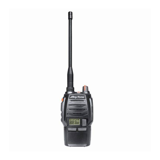
- Page 4 929 is a compact and fashionable transceiver that allows you to enjoy instant communication at ease. The features like novelty, nice timbre, high power (4W), make 929 a high cost-effective professional transceiver.
- Page 5 SAFETY INFORMATION FOR USER Our transceiver is excellently designed with advanced technology. Please observe the following precautions to perform your obligation, prevent personal injury and ensure the safety of transceiver usage. 1. Keep the transceiver and accessories away from children. 2.
-
Page 6: Table Of Contents
CONTENTS UNPACKING ..................01 Supplied Accessories ..................01 STANDARD ACCESSORIES/OPTIONAL ACCESSORIES ....02 Standard Accessories ..................02 Optional Accessories ..................02 BATTERY INFORMATION ..............03 Charging the Battery Pack ................03 Charger Applied ....................03 NOTES ......................03 How to Store the Battery ................04 Emergent Charging .................. - Page 7 CONTENTS CTCSS/DCS Encode/Decode ............... 17 CTCSS/DCS Encode/Decode Setup .............. 17 Mode Selection ....................18 FM Radio ....................... 18 Beep Voice Prompt ..................19 Squelch Level Setup ..................19 On/Off VOX ....................20 VOX Level Setup .................... 20 Frequency Step Setup ..................20 ADVANCE OPERATIONS ..............
-
Page 8: Unpacking
UNPACKING Carefully unpack the transceiver. We recommend you identify the items listed in the table as bellows before discarding the packing material. If any items are missing or have been damaged during shipment, please contact local dealers immediately. Supplied Accessories Item Number Quantity... -
Page 9: Standard Accessories/Optional Accessories
STANDARD ACCESSORIES/OPTIONAL ACCESSORIES Standard Accessories Antenna * Charger AC Adaptor Li-ion Battery QBC-33L (12V/500mA) Pack)1300mAh QA07V(400-470MHZ) QPS-05 QB-33L Belt Clip BC06 Instruction Manual Note: For frequency band of antenna, please refer to label glued on the bottom of the antenna. Optional Accessories Earphone HS03 Backup Li-ion Battery... -
Page 10: Battery Information
BATTERY INFORMATION Charging the Battery Pack The battery pack is not charged at the factory; please charge it before use. Charging the battery pack for the first time after purchase or extended storage (more than 2 moths) may not bring the battery pack to its normal operating capacity. -
Page 11: How To Store The Battery
BATTERY INFORMATION • Do not charge the battery or transceiver if it is damp. Dry it before charging to avoid danger. WARNING: When keys, ornamental chain or other electric metals contact with the battery terminal, the battery may cause damage or hurt bodies. -
Page 12: Emergent Charging
BATTERY INFORMATION Working Indicator Battery Charge Transceiver Charge Charging Indicator Plug the Li-ion battery or the transceiver installed with Li-ion battery into the matched charger. A. Make sure that the battery is well connected with charging connectors. Charging indicator---Red Fully charged. Charging indicator--Green. Note: It takes approximately 4 hours to fully charge the battery. -
Page 13: Preparation
PREPARATION Installing / Removing the Battery ■Installing the battery: Match the battery pack with the corresponding guides on the back of the transceiver, and push it upwards till it is fully locked by the battery latch. ■Removing the battery pack: Slide up the battery latch and remove the pack away from the transceiver. -
Page 14: Installing / Removing The Belt Clip
PREPARATION Installing / Removing the Belt Clip ■Installing the Belt Clip: Place the belt clip to the corresponding grooves on the back of the transceiver, and then clockwise screw it. ■Removing the Belt Clip: Anticlockwise turn the screws to remove the belt clip. -
Page 15: Getting Acquainted
GETTING ACQUAINTED LCD Display Screen On the screen, icons for the optional functions are displayed on the screen. It helps a lot when you forget the functions settings. TX Power Narrow Band Transmitting Voice Compander Keypad Lockout Battery Capacity CTCSS FM Radio Code group/Function Channel/... - Page 16 GETTING ACQUAINTED...
- Page 17 GETTING ACQUAINTED Antenna POWER / VOLUME Switch: Turn clockwise to switch on the transceiver, and turn anticlockwise till hearing "Ka" to switch off the transceiver. After switching on the transceiver, turn clockwise to increase the volume and anticlockwise to decrease the volume. Jacklight: under standby state, press this key to Emergency Alarm Key to power on the jacklight.
-
Page 18: Backlight Status And Voice Prompt
GETTING ACQUAINTED Backlight Status and Voice Prompt Transceiver emits a low voltage beep Warning on low voltage at intervals of 60 seconds, and red light twinkles. Receive Backlight lightens all the time Transceiver emits"DU" when entering Keypad operation a function menu, "DU DU" to exit any function. -
Page 19: Auxiliary Functions
AUXILIARY FUNCTIONS Users can setup the key [PF1] and PF2] to be one of the optional functions as bellows: • Squelch off • Monitor • Hi/Low Power switch • Scan • Frequency Reverse • Talk around • Current battery capacity enquiry •... -
Page 20: Basic Operations
BASIC OPERATIONS Switch on / off the Transceiver Switch on the Transceiver: Under power-off state, turn POWER/ VOLUME knob clockwise till hearing "Click" to switch on the transceiver. The transceiver will announce "Power on" and current channel. Switch off the Transceiver: When the transceiver is in the open state, turn POWER / VOLUME anticlockwise till hearing "Click"... -
Page 21: Fast Adjust Frequency
BASIC OPERATIONS dot on the LCD twinkles. Under this state, press to set desired current frequency. Press to increase the frequency value by step, to decrease the frequency value. Press [PF1] or [PF2] key to confirm the selected frequency and exit the frequency setting mode. After entering the setting mode, if users do not set the frequency or not exit the mode after adjusting the frequency, the transceiver will exit the setting mode automatically... -
Page 22: Receiving
BASIC OPERATIONS need to press repeatedly till the channel number displayed on the LCD twinkles, secondly, press to up or down the channel number, and then the transceiver will announce the adjusted channel number. Press to upward the channel number and to downward the channel number. -
Page 23: Emergency Alarm Function
BASIC OPERATIONS into microphone. Please keep around 2.5-5cm distance between microphone and your lip. And please speak in normal tone to make the receiver obtain best tone quality. Note: Pressing and holding [PTT], if the backlight lightens for 10seconds and goes out afterwards and TX icon displayed on the LCD, the transceiver is transmitting. -
Page 24: Functions Setup
FUNCTIONS SETUP Basic Functions Setup 1. Press repeatedly to select desired sub-menu to setup. 2. Press to set desired function value. 3. Press [PF1] or [PF2] to save and exit. CTCSS/DCS Encode/Decode When the transceiver is edited with this function, only when CTCSS/DCS signaling is received can the transceiver hear the calling of the other party. -
Page 25: Mode Selection
FUNCTIONS SETUP Press to select desired CTCSS/DCS decode. CTCSS: 67-254.1H, totally 50 groups. Default: 67HZ. DCS: 017N-765I, totally 232 groups. "N" on the LCD means positive code. "I" on the LCD means inverse code. Default: 017N Press [PF1] or [PF2] to save and back to standby state. -
Page 26: Beep Voice Prompt
FUNCTIONS SETUP OFF: turn off FM radio function (reset the transceiver when FM radio is on can also turn this function off) Press [PF1] or [PF2] to exit. NOTE: When FM radio function is on, press to search FM radio station and announce current channel number. When a certain radio station is detected, the radio will rest on the station. -
Page 27: On/Off Vox
FUNCTIONS SETUP On/Off VOX When this function is enabled, you can begin transmitting by fitted high voice, no needing to press the [PTT] key. Press repeatedly till "VOX" on the LCD twinkles. Press to on/off VOX function. ON: turn on VOX function OFF: turn off VOX function Press [PF1] or [PF2] to exit. - Page 28 FUNCTIONS SETUP channel mode. Under VFO mode, users can upward or downward the frequency by frequency step. Under standby state, Press repeatedly till "STP" icon and current value of frequency step are displayed on the LCD. Press to select desired value. There are five options: 5k, 6.25k, 10k, 12.5k.
-
Page 29: Advance Operations
ADVANCE OPERATIONS [PF1] and [PF2] are programmable, which can realize certain functions as bellows via programming software. NOTE: To start the function programmed on the [PF1]-1s or [PF2]-1s, users need to press and hold [PF1] or [PF2] till the transceiver voice "DU"... -
Page 30: Scan
ADVANCE OPERATIONS "H" icon on the LCD means high power. "L" icon on the LCD means low power 2. Scan Scan function can be used to monitor every channel. Under the standby state, pressing the programmed "Scan" key, transceiver emits "Du" beep and comes into scan state. It scans channels in scan list one by one. -
Page 31: Battery Capacity Enquiry
ADVANCE OPERATIONS Note: Under the talk around state, the transceiver can not communicate with other transceivers via repeaters. Battery Capacity Enquiry Pressing the programmed "Battery Capacity Enquiry", the transceiver will announce current battery capacity. There are 10 grades in total. Grade 10th means full battery capacity. When the battery state is grade 1th(6.1V), the LED lights red. - Page 32 ADVANCE OPERATIONS deletes this channel from scan list. But the priority channels cannot be temporarily deleted. If only one or two channels are in scan list, this operation is not available. Restart the transceiver to add the temporarily deleted channels into scan list again.
-
Page 33: Background Operations
BACKGROUND OPERATIONS Wide / Narrow Band Setup On the basis of national conditions, users can set channel spacing as 12.5K (narrow band) to communicate on the transceiver by programming software. This transceiver can realize 12.5K (narrow band) etc as communication way. NOTE: "N"... -
Page 34: Time-Out Timer Pre-Alarm
BACKGROUND OPERATIONS using a channel for an extended period of time. If you continuously transmit for a period of time that exceeds the programmed time set in advance, the transceiver will stop transmitting with voice prompt. Users can set TOT timer by programming software. Time-Out Timer Pre-Alarm The Time-Out Timer Pre-Alarm is to alarm users that overtime transmission is pending. - Page 35 BACKGROUND OPERATIONS This transceiver is setup with different ways to return to appointed channel. Users can choose the desired way by programming software. NOTE: Users can set the basic and advanced operations via programming software.
-
Page 36: Windows Xp As An Example)
Resume Factory Default Once transceiver works abnormally for wrong operations or wrong programming, users can start this function to resume all functions and channels as Factory Default. Press [PTT] and [PF1] key synchronously to switch on transceiver. Holding the two keys for more than 1 second, the transceiver will resume Factory Default after announcing current channel number. - Page 37 TECHNICAL SPECIFICATIONS General Frequency Range UHF:400-470MHZ Channel Capacity 128 channels Channel Spacing 12.5KHz Phase-locked Step 5KHz, 6.25KHz Operating Voltage 7.4 DC ±20% More than 8 Hours (5-5-90 duty Battery Life cycle with 1200mAh Libattery) Frequency Stability ±2.5ppm Operating Temperature -20~ +60℃ Size 108×56×32mm (with battery pack, no antenna) Weight...
-
Page 38: Technical Specifications
TECHNICAL SPECIFICATIONS Transmitting Part 4W/1W Power Output 11KΦF3E Modulation ≥65dB Adjacent Channel ≥40dB Hum & Noise Spurious Emission ≤-36dB 6dB / per interval Audio Response ≤5% Audio Distortion Note: No further advice when any necessary amendments are made for technical need. - Page 39 TROUBLE SHOOTING GUIDE Problem Corrective Action A.The battery pack may be exhausting. Recharge or replace the battery pack. B. The battery pack may not be installed correctly. Remove the battery pack and install it again. No power. C. The power switch is broken; send it to local dealers to repair.
-
Page 40: Trouble Shooting Guide
TROUBLE SHOOTING GUIDE Can not power on or Check whether the battery touch is out of frequent power-off sharp or broken. The other party gets low Check weather the MIC is stoppage. or intermittent receiving (Otherwise, please contact with local sound dealers to repair it.) Out of communication range or obstruct... -
Page 41: Ctcss Frequency Chart
ATTACHED CHART CTCSS Frequency Chart 67.0 97.4 23 141.3 34 179.9 45 225.7 69.3 13 100.0 24 146.2 35 183.5 46 229.1 71.9 14 103.5 25 151.4 36 186.2 47 233.6 74.4 15 107.2 26 156.7 37 189.9 48 241.8 77.0 16 110.9 27 159.8 38 192.8 49 250.3... -
Page 42: Attached Chart
ATTACHED CHART DCS Chart 017 21 446 101 627 023 22 452 102 631 025 23 454 103 632 026 24 455 104 645 031 25 462 105 654 032 26 464 106 662 036 27 465 107 664 043 28 466 108 703 047 29 503 109 712...
Need help?
Do you have a question about the 929 and is the answer not in the manual?
Questions and answers