AnyTone AT-D878UV Operating Manual
Hide thumbs
Also See for AT-D878UV:
- Operating manual (52 pages) ,
- Firmware manual (8 pages) ,
- Operating manual (60 pages)

Related Manuals for AnyTone AT-D878UV


Summary of Contents for AnyTone AT-D878UV
- Page 1 AT-D878UV Digital DMR and Analog UHF/VHF Two Way Radio DIGITAL MOBILE RADIO ASSOCIATION Operating Manual...
- Page 3 It offers great stability, and reliability, together with long distance communication as well as fashionable design and compant exterior lines. AT-D878UV has Text message, recording, voice message, digital encryption, emergency alarm, Man down alarm, lone work, GPS,APRS Location Reporting, Vibration, Analog DTMF, 2TONE 5TONE, CTCSS/DCS encode/decode functions.
-
Page 4: Table Of Contents
CONTENTS 1.UNPACKING AND CHECKING THE EQUIPMENT ......1 1.1 Supplied Accessories ..............1 1.2 Standard Accessories ..............2 1.3 Optional Accessories ..............2 2.BATTERY INFORMATION .............. 3 2.1 Charging the Battery Pack ............3 2.2 Charger Supplied ............... 3 2.3 Use Caution with the Li-ion Battery ..........3 2.4 How to Charge ................ - Page 5 5.10 New Channel .................15 5.11 Delete Channel ............... 15 5.12 Receiving and Responding to a Radio Call ......16 5.13 Making a Call ................16 5.14 Monitor ..................17 5.15 Digital Monitor ................ 5.16 Response and Save a call in Digital Monitor mode ....
- Page 6 9.8 Blue Tooth(Optional) ..............9.9 Reset ..................38 10.TROUBLE SHOOTING GUIDE ........... 39 11.PROGRAMMING GUIDE ............40 12.ON-LINE SERVICE AND SUPPORT .......... 42 13.SAFETY ..................43 14.EU DECLARATION OF CONFORMITY ........45 15.TECHNICAL SPECIFICATIONS ..........46...
-
Page 7: Unpacking And Checking The Equipment
1. UNPACKING AND CHECKING THE EQUIPMENT Unpack the radio carefully. We recommend that you identify the items listed in the following table before discarding the packing materials. If any items are missing or have been damaged during shipment, please contact the carrier or the dealers immediately. -
Page 8: Standard Accessories
1. UNPACKING AND CHECKING THE EQUIPMENT Standard Accessories Antenna* Li-ion Battery Pack Charger AC Adaptor QBC-45L QPS-17 QA-11UV QB-44HL(3100mAh) USB Programming Belt Clip Instruction Manual PC-04 BC-05 Optional Accessories Earphone Li-ion Battery Pack Programming Software EJX-023 QB-44HL(3100mAh) Car Charger Battery Eliminator CPL-01 CPS-02 AT-D87 8UV Digital DMR and Analog UHF/VHF Two Way Radio... -
Page 9: Battery Information
Use Caution with the Li-ion Battery attempt to remove the casing from the battery pack, as AnyTone cannot be held responsible for any accident caused by modifying the battery. The ambient temperature should be between 5 -40 while charging the battery. -
Page 10: How To Charge
2. BATTERY INFORMATION WARNING: When keys, ornamental chain or other electric metals contact the battery terminal, the battery may become damage or injure a human. If the battery terminals are short circuited it will generate a lot of heat. Take care when carrying and using the battery. Remember to put the battery or radio into an insulated container. -
Page 11: Normal Charging Tips
2. BATTERY INFORMATION e. Charging Process Charging Status Indicator Status Standby (Self-examine lights red None 1second when power on) Charging Lights red for about 3 hours (Charge in a constant current) Fully charged Lights green (Charge in a constant voltage) f. -
Page 12: How To Store The Battery
2. BATTERY INFORMATION Trickle charging (Pre-Charging Mode) time cannot last beyond 30 minutes. If the indicating lamp still blinks red after 30-minute trickle-charging, it means that the charger cannot charge the battery correctly. Please check whether the battery or charger is damaged. -
Page 13: Preparation
3. PREPARATION Installing / Removing the Battery Match the two bottom grooves of the battery pack with the corresponding guides on the back of the radio and then push it. To remove the battery pack, slide the release latch at the top away from the battery and remove the pack away from the transceiver. -
Page 14: Installing / Removing The Belt Clip
3. PREPARATION Installing / Removing the Belt Clip Installing the Belt Clip: Place the belt clip above the corresponding holes on the back of the radio, and screw it into place clockwise with the two supplied screws. Removing the Belt Clip:Unscrew counter-clockwise to remove the belt clip. -
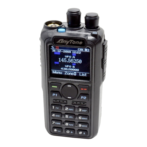
Page 15: Radio Overview
4. RADIO OVERVIEW Emergency Alarm Key (PF3) Channel Switch Antenna POWER/VOL Status Indicator Menu key Exit Key P1 key/ P2 key Speaker MIC Input PTT Button Speaker/Mic Jacks [PF1]/[PF2] Key AT-D87 8UV Digital DMR and Analog UHF/VHF Two Way Radio... -
Page 16: Led Indications
4. RADIO OVERVIEW Status Indications The top LED will help you to identify the current radio status. LED Indication Status Flashes Red Low battery voltage Constant Red Transmitting Constant Green Analog Receiving Constant Cyan Digital Receiving Flashes Green Scan Programmable Key It is possible to set different functions for [PF1], [PF2], [PF3], keys. -
Page 17: Programmed Key
4. RADIO OVERVIEW Main Choose Choose channel A or channel B as the main channel One Touch 1~6 hot key setup details in next page. Work Alone Turn on/off the work alone function. Nuisance Delete During scanning, press the key to skip the unwanted channel Digi Monitor In DMR mode, press the key to turn on/off digital monitor Sub CH Switch... -
Page 18: Hot Key
4. RADIO OVERVIEW Hot Key Setting for PF1, PF2, PF3, P1, P2 Enter radio Menu - Settings - Radio Set - PF1, PF2,PF3,P1,P2,sub menu. users can choose One Touch 1-6 (Also called Hot Key 1 - 6 ) Hot Key function details shall be setup in PC software – Public – Hot key Analog the hot key set. -
Page 19: Basic Operations
5. BASIC OPERATIONS Power on the radio Turn on the radio by turning the [Power/Volume] switch clockwise till a click is heard, and the LCD displays will show a start-up message, and you will hear a beep after 7seconds. Adjust Volume Rotate the [Power/Volume] knob to adjust the volume. -
Page 20: Select A Zone
5. BASIC OPERATIONS Select a Zone A Zone is a group of channels grouped together. The D878UV DMR radio has 250 Zones. A Zone can have the maximum of 160 analog and/or digital channels. Operation 1: Press directly to switch the zone, the LCD will display the selected zone number or name. -
Page 21: New Channel
5. BASIC OPERATIONS channel 99, input 0+0+9+9 a total of 4 digits, and it will switch to channel A channel can either be Analog or Digital. For the analog channels the Push-To-Talk button is always available, and on the Digital Channels parameters can be set up by the users / system operators by channel to allow talk permit. -
Page 22: Receiving And Responding To A Radio Call
5. BASIC OPERATIONS 5.12 Receiving and Responding to a Radio Call When the radio is in the digital mode, it can receive and respond to a call with the same frequency/color code/ slot. When receiving a call: If the radio is programed with callers DMR ID number in the digital The blue LED lights up. -
Page 23: Monitor
5. BASIC OPERATIONS 5.14 Monitor In standby, press the [PF2] key to enter Monitor. When receiving matched carrier but the signaling / ID is unmatched or the signal is too weak, this function allows monitor the weak signal and signal with unmatched ID. Press the [PF2] key again to shut off speaker and return to standby. -
Page 24: Emergency Alarm
5. BASIC OPERATIONS 5.17 Emergency Alarm Press Emergency Alarm key to turn alarm function, then press this key again to return. 5.18 Man Down Alarm Press (Menu) to enter main Menu, press key to Settings. Select Radio Set, press key to Man Down. Select Man Down On to turn on the function. -
Page 25: Advanced Features
6. ADVANCED FEATURES Advanced Features for Private Call Method 1: Access from Contact list Press the (Exit) key to enter the Contact list, press the to a private call ID name. Press Select to View Contact, press Select to see the contact information. - Page 26 6. ADVANCED FEATURES Kill Select Kill, and it will send out a kill signaling to the target radio which will be killed (No display, no operation) when receiving the signaling and it will send back a kill successful message to the transmit radio. Wake Select Wake, and it will send out a wake signaling to the killed radioand the target radio will return to standby when it receives this signaling and send...
-
Page 27: Gps Positioning Function
7. GPS POSITIONING FUNCTION(OPTIONAL) Turn on GPS Press (Menu) to enter the main Menu. Select "GPS" Select "GPS On". Check GPS Information Method 1: Check GPS info from Menu Press (Menu) key to enter Main Menu, select " GPS", then select "GPS Info" Method 2: Check GPS info from programmed key In the PC software, Public –... -
Page 28: Recording
8. RECORD The voice record is designed for security use purpose. Each call will The standard voice 10hours record allows in DMR mode only. The optional 500 hours voice record allow in both DMR or analog mode. Turn on/ off the Recording Press (Menu) enter main Menu, press key to Record. -
Page 29: Recording Manually
8. RECORD Recording Manually In the PC software, Public – Optional Setting – Key function, program a key as Record. Press the programmed Record key, and the radio will start the recording, and speak into the microphone. Select Record Play, and the radio will play the record. Select Record Send, and the radio will display Contact list or Manual Dial. -
Page 30: Main Menu
9. MAIN MENU Contacts Contacts List: Will display the digital contact list which had been programmed in the PC software. This list is used as a look-up table to display the contact person information when receiving a call. New Contact: Allows to create a new digital contact. - Page 31 9. MAIN MENU 9.4.2 Scan list Operation Press (Menu) to enter the main Menu. Select "SCAN" c. Select " Scan List' d. Select a scan list and press to enter scan list sub menu. Select scan list Select "Select Cu list", and press to add current list into working scan list.
-
Page 32: Settings
9. MAIN MENU Settings 9.5.1 Radio Set Beep Beep On: The radio will beep when you press the keypad Beep Off: No beep when you press the keypad. Back Light LCD backlight intensity is adjustable in 5 steps Light Time Always: The backlight is always on. - Page 33 When the time is reached, the radio will auto exit the menu. (13) Intro Display (Power on display) Picture: The radio will display an AnyTone picture when powered on. Character: The radio will display the characters set up in PC software when powered on.
- Page 34 9. MAIN MENU (18) Msg Note Different prompt options when receive a new message. (19) Call Ring Different prompt options when receive a new call. (20) Freq Step 2.5K,5K,6.25K,10K,12.5K,20K,25K,30K,50K, total of 9 frequency steps (21) Ana SQ Level Adjusts the squelch level to receive signal with different signal strength, and a total of 5 levels offered.
- Page 35 9. MAIN MENU (27) Mic Level Allows to adjust the Microphone gain, level 1 is the lowest, level and 5 is highest gain. (28) DTMF Speed Offers DTMF encode speed which will help the receiver decode successfully, 50~500ms are the options. (29) FM Radio Turn on or off the FM radio.
- Page 36 9. MAIN MENU (35-44) Key PF1, PF2, PF3, P1, P2 You can program these keys for different functions.(Refer to page 10 & 11 ) (45) Roaming Timing Set up the time interval for automatical roaming. The radio will search repeater list and lock on the strongest signal one.
-
Page 37: Chan Set
9. MAIN MENU 9.5.2 Chan Set Channel set menu Route: Main Menu- Settings - Chan Set. The channel set menu will change accordingly to the channel type. When the channel type is digital, it will automatical hide the analog menus Chan Set (Digital channel) Store Chan Allows to store current channel and its setup. - Page 38 9. MAIN MENU TX Freq Input the TX frequency by keypad, click the Menu key to save, press P2 key to return. Talk Around When the TX radio and RX radio both are set up with Talk Around on, they can communicate directly without a repeater.
- Page 39 9. MAIN MENU (16) Digi Encrypt of 32 digital encryptions is offered, and it can be programmed in the PC (17) Encrypt Type Choose normal encryption or enhanced encryption type. (18) RX Group List It will allow edit the RX Group List and assign a new RX Group List to the channel.
- Page 40 9. MAIN MENU Repeater: Enable talk with other radio by repeat frequency throught repeaters. Double Slot When TX/RX frequency is same, turn on this function to communicate by the slot set in simplex mode. If DMR mode not choosed Doulbe Slot, the radio will work on Slot in repeat mode.
- Page 41 9. MAIN MENU SQ: You can hear the call once the channel receive matched carrier. CDT: You can hear the call when receive matched CTCSS/DCS signal TONE: You can hear the call when receives a matched signaling. C&T: You can hear the call when receives a matched CTCSS/DCS and matched signaling.
-
Page 42: Device Info
9. MAIN MENU 9.5.3 Device Info Show the Radio ID, Radio name, serial number, model name, frequency version, language version etc. Roaming APRS Location Reporting(Supported by GPS) Upload Type Press (Menu) to enter the main Menu. Select "APRS" Select "Upload Type" d. -
Page 43: Blue Tooth(Optional)
9. MAIN MENU APRS Infor Press (Menu) to enter the main Menu. Select "APRS" Select "APRS Infor" to check stored received APRS information. select "Delete All" to delete all APRS history. Upload Power Press (Menu) to enter the main Menu. Select "APRS"... -
Page 44: Reset
9. MAIN MENU Reset Then power it on while holding the [PTT] and the [PF1] button below the PTT at the same time. The radio will start up with a note on the display - Are you sure you want to intialize radio. -
Page 45: Trouble Shooting Guide
10. TROUBLE SHOOTING GUIDE Problems Solutions A. Battery pack may not be installed properly. Remove the battery pack The radio cannot be switched and install it again. on or no display after being switched on. Recharge or replace the battery pack. -
Page 46: Programming Guide
In addition, Multiple Radio ID’s The AT-D878UV radio will allow multiple DMR Radio ID numbers to be used with the radio. This feature will allow one radio to be used for example as a Commercial Radio with its own DMR ID, and at the same time also be used as an Amateur radio with another DMR ID. - Page 47 Worldwide Amateur Contact Database The AT-D878UV DMR radios contain a separate database memory for importing and displaying Amateur DMR individual IDs, call sign and user name in comma-delimited format (.csv) Please reference in the programming guide for import and export database operations detailed.
-
Page 48: On-Line Service And Support
12. ON-LINE SERVICE AND SUPPORT The Anytone website provides additional information about obtaining service or support for the Anytone line of two-way radios . Visit: www.anytone.net Warning Notes Every effort has been made to ensure that the information in this document is complete, accurate, and up to-date. -
Page 49: Safety
Grasp the handheld by its base (not the antenna) when you need to place or remove it. parts of the body, while transmitting. Anytone radios will perform best, if you speak 2-4 inches away from the microphone and the radio is vertical. - Page 50 This could result in short circuiting the battery. supplied battery charger (AC adapter). If you are not sure, check with your authorized Anytone dealer. or place anything on it as this could result in a damaged charger power cord.
-
Page 51: Eu Declaration Of Conformity
RE Directive 2014/53/EU. 1. INFORMATION ON THE EQUIPMENT Product: Digital DMR and Analog UHF/VHF Two Way Radio Model Name: AT-D878UV 2. INFORMATION ON THE MANUFACTURER Manufacturer: Qixiang Electron Science & Technology Co., Ltd. Qixiang Building,Tangxi Industrial Zone,Luojiang... -
Page 52: Technical Specifications
15. TECHNICAL SPECIFICATIONS General Frequency Range 136-174MHz (V) , 400-480MHz (U) Channel Capacity 4000 channels Channel Spacing 12.5KHz (Narrow Band) Phase-locked Step 5KHz, 6.25KHz Operating Voltage 7.4V DC ±20% Frequency Stability ±2.5ppm Operating Temperature -10 ~ +40 Size 129×61×39mm (with battery pack) Weight 282g (with battery pack, antenna) Receiving Part... - Page 53 European Users should note that operation of this unit in Transmit mode requires the operator to have a valid Amateur Radio Licence from their respective Countries Amateur Radio Licencing Authority for the Frequencies and Transmitter Power levels that this Radio transmits on. Failure to comply may be unlawful and liable for prosecution.
- Page 54 FCC NOTICES FCC STATEMENTS WARNINGAND COMPLIANCE STATEMENT: This device complies with Part 15 of the FCC Rules. Operation is subject to the following two conditions: (1) This device may not cause harmful interference. (2) This device must accept any interference received, including interference that may cause undesired operation.
- Page 55 FCC STATEMENTS WARNINGAND COMPLIANCE STATEMENT: Electromagnetic Interference/Compatibility During transmissions, The radio generates RF energy that can possibly cause interference with other devices or systems. To avoid such interference, turn off the radio in areas where signs are posted to do so. DO NOT operate the transmitter in areas that are sensitive to electromagnetic radiation such as hospitals, aircraft,and blasting sites.
- Page 56 FCC PART 15.21 WARNING STATEMENT This equipment has been tested and found to comply with the limits for a Class B digital device, pursuant to Part 15 of FCC Rules. These limits are designed to provide reasonable protection against harmful interference in a residential installation.
- Page 57 FCC PART 15.21 WARNING STATEMENT Licensing Information Use of the radio in USA is subject to the rules & regulations of FCC. Changes or modifications not expressly approved by our may void the user authority granted by the FCC to operate this radio and should not be made. To comply with FCC requirements, transmitter adjustments should be made only by or under the supervision of a person certified as technically qualified to perform transmitter maintenance and repairs in the private land mobile and fixed services as certified...
- Page 58 A4.180526...
Need help?
Do you have a question about the AT-D878UV and is the answer not in the manual?
Questions and answers
What is and where can I find the rdt file?
The RDT file for the AnyTone AT-D878UV is a codeplug file used by the radio programming software. It contains configuration settings such as channels, frequencies, IDs, and other radio parameters. It can be opened in the programming software by selecting the "Open File" icon on the top bar, not through the "Import" function.
This answer is automatically generated
Where would I find the rdt file?
The RDT file for the AnyTone AT-D878UV can be obtained by downloading a codeplug, such as the example mentioned in the context. It is not imported through the "Import" function in the software but opened directly using the "Open File" icon on the top bar of the D878UV software.
This answer is automatically generated