Table of Contents
Advertisement
Quick Links
Advertisement
Table of Contents

Related Manuals for GE AKTA avant


Summary of Contents for GE AKTA avant
- Page 1 ÄKTA ™ avant Operating Instructions Original instructions...
-
Page 2: Table Of Contents
Table of Contents Table of Contents Introduction ......................About this manual ..........................Important user information ......................Regulatory information ........................1.3.1 EU Directives ............................ 1.3.2 Eurasian Customs Union ......................1.3.3 Regulations for USA and Canada ................... 1.3.4 Other regulations and standards .................... Associated Documentation ...................... - Page 3 Table of Contents Prepare the system for a run ................Before you prepare the system ...................... Prepare the flowpath .......................... Prime buffer inlets and purge system pumps ................. Connect a column ..........................Set pressure alarms ..........................Calibrate the pH monitor ........................Prepare the built-in fraction collector ..................
-
Page 4: Introduction
1 Introduction Introduction About this chapter This chapter contains important user information, descriptions of safety notices, regula- tory information, intended use of the ÄKTA avant instrument, and lists of associated documentation. In this chapter Section See page 1.1 About this manual 1.2 Important user information 1.3 Regulatory information 1.4 Associated Documentation... -
Page 5: About This Manual
1 Introduction 1.1 About this manual About this manual Purpose of this manual The Operating Instructions provide you with the information needed to install, operate and maintain the product in a safe way. Scope of this manual The Operating Instructions cover ÄKTA avant 25 and ÄKTA avant 150 instruments, using previously created methods in UNICORN software 6.3.2 and later. -
Page 6: Important User Information
1 Introduction 1.2 Important user information Important user information Read this before operating the product All users must read the entire Operating Instructions before installing, operating or maintaining the product. Always keep the Operating Instructions at hand when operating the product. Do not operate the product in any other way than described in the user documentation. - Page 7 1 Introduction 1.2 Important user information Safety notices This user documentation contains safety notices (WARNING, CAUTION, and NOTICE) concerning the safe use of the product. See definitions below. WARNING WARNING indicates a hazardous situation which, if not avoided, could result in death or serious injury. It is important not to proceed until all stated conditions are met and clearly understood.
-
Page 8: Regulatory Information
This section lists the regulations and standards that apply to the ÄKTA avant instrument. Manufacturing information The table below summarizes the required manufacturing information. Requirement Information Name and address of manufacturer GE Healthcare Bio-Sciences AB, Björkgatan 30, SE 751 84 Uppsala, Sweden In this section Section See page 1.3.1 EU Directives 1.3.2 Eurasian Customs Union... -
Page 9: Eu Directives
• used according to the Operating Instructions or user manuals, and • used in the same state as it was delivered from GE, except for alterations described in the Operating Instructions or user manuals. ÄKTA avant Operating Instructions 29101556 AB... -
Page 10: Eurasian Customs Union
Telephone: + 46 771 400 600 Importer and/or company for obtain- GE Healthcare LLC ing information about importer GE Healthcare Life Sciences Presnenskaya nab., 10C, 12th floor RU-123 317 Moscow, Russian Federation Telephone 1: + 7 495 411 9714 Fax nr: + 7 495 739 6932 Email: LSrus@ge.com... -
Page 11: Regulations For Usa And Canada
The user is cautioned that any changes or modifications not expressly approved by GE could void the user’s authority to operate the equipment. This equipment has been tested and found to comply with the limits for a Class A digital device, pursuant to part 15 of the FCC Rules. -
Page 12: Other Regulations And Standards
1 Introduction 1.3 Regulatory information 1.3.4 Other regulations and standards 1.3.4 Other regulations and standards Introduction This section describes the standards that apply to the ÄKTA avant system. Environmental conformity This product conforms to the following environmental requirements. Requirement Title 2012/19/EU Waste Electrical and Electronic Equipment (WEEE) Directive China RoHS... - Page 13 1 Introduction 1.3 Regulatory information 1.3.4 Other regulations and standards Standard Description EN 300 330-2 Electromagnetic compatibility and Radio spectrum Matters (ERM); Short Range Devices (SRD); Radio equip- ment in the frequency range 9 kHz to 25 MHz and induc- tive loop systems in the frequency range 9 kHz to 30 MHz;...
-
Page 14: Associated Documentation
1 Introduction 1.4 Associated Documentation Associated Documentation Introduction This section describes the user documentation that is delivered with ÄKTA avant. User documentation on the CD The user documentation listed in the table below is available in printed or PDF format. The complete documentation is also available on the User Documentation CD. - Page 15 1 Introduction 1.4 Associated Documentation Documentation Main contents Getting started with Video clips showing common workflows in the • Evaluation Evaluation module. Note: Overview of features of the Evaluation module. • Available in UNICORN 7.0 and later. UNICORN Method Manual Overview and detailed descriptions of the method •...
- Page 16 1 Introduction 1.4 Associated Documentation Additional literature For practical tips on chromatography, refer to ÄKTA Laboratory-scale: Chromatography Systems Instrument Management Handbook (product code 29010831). ÄKTA avant Operating Instructions 29101556 AB...
-
Page 17: Safety Instructions
2 Safety Instructions Safety Instructions About this chapter This chapter describes safety precautions, labels and symbols that are attached to the equipment. In addition, the chapter describes emergency and recovery procedures, and provides recycling information. Important WARNING Before installing, operating or maintaining the product, all users must read and understand the entire contents of this chapter to become aware of the hazards involved. -
Page 18: Safety Precautions
2 Safety Instructions 2.1 Safety Precautions Safety Precautions Introduction ÄKTA avant is powered by mains voltage and handles materials that may be hazardous. Before installing, operating or maintaining the system, you must be aware of the hazards described in this manual. Follow the instructions provided to avoid personal injuries or damage to the product, or to other personnel and equipment in the area. - Page 19 2 Safety Instructions 2.1 Safety Precautions WARNING • Only properly trained personnel may operate and maintain the product. • Before connecting a column, read the instructions for use of the column. To avoid exposing the column to excessive pres- sure, make sure that the pressure limit is set to the specified maximum pressure for the column.
- Page 20 2 Safety Instructions 2.1 Safety Precautions WARNING • Spread of biological agents. The operator must take all nec- essary actions to avoid spreading hazardous biological agents. The facility must comply with the national code of practice for biosafety. • High pressure. The product operates under high pressure. Wear protective glasses and other required Personal Protective Equipment (PPE) at all times.
- Page 21 2 Safety Instructions 2.1 Safety Precautions WARNING • Fraction collector. Do not fractionate flammable liquids in the built-in fraction collector. When running RPC methods, collect fractions through the outlet valve or the optional external Fraction collector F9-R. • RPC runs with 100% acetonitrile and system pressure above 5 MPa (50 bar) in ÄKTA avant 25.
- Page 22 WARNING • Power cord. Only use power cords with approved plugs deliv- ered or approved by GE. • Access to power switch and power cord with plug. Do not block access to the power switch and power cord. The power switch must always be easy to access.
- Page 23 2 Safety Instructions 2.1 Safety Precautions NOTICE • Any computer used with the equipment must comply with EN/IEC 60950-1, and be installed and used according to the manufacturer's instructions. System operation WARNING To avoid personal injury when operating the ÄKTA avant system, follow these instructions.
- Page 24 2 Safety Instructions 2.1 Safety Precautions WARNING • Over-pressure. Never block the outlet tubing with, for instance, stop plugs, since this will create over-pressure and might result in injury. • Hazardous chemicals during run. When using hazardous chemicals, run System CIP and Column CIP to flush the entire system tubing with distilled water, before service and mainte- nance.
- Page 25 2 Safety Instructions 2.1 Safety Precautions NOTICE To avoid damage to the ÄKTA avant instrument or other equipment when operating the instrument, follow these instruc- tions. • Keep UV flow cell clean. Do not allow solutions containing dissolved salts, proteins or other solid solutes to dry out in the flow cell.
- Page 26 WARNING • Electrical shock hazard. All repairs should be done by service personnel authorized by GE. Do not open any covers or replace parts unless specifically stated in the user documentation. • Disconnect power. Always disconnect power from the instru- ment before replacing any component on the instrument, un- less stated otherwise in the user documentation.
-
Page 27: Labels
2 Safety Instructions 2.2 Labels Labels Introduction This section describes the system label and other safety or regulatory labels that are attached to the product. Labels on the ÄKTA avant instrument The following illustration shows the labels that are attached to the ÄKTA avant instrument. ÄKTA avant Operating Instructions 29101556 AB... - Page 28 Warning! Read the Operating Instruction before using the system. Electrical shock hazard. All repairs should be done by service personnel authorized by GE. Do not open any covers or replace parts unless specifically stated in the user documentation. Supply voltage. Before connecting the power cord, make sure that the supply voltage at the wall outlet corresponds to the marking on the instrument.
- Page 29 2 Safety Instructions 2.2 Labels Label Meaning This symbol indicates that the product contains hazardous materials in excess of the limits established by the Chinese standard GB/T 26572 Requirements of concentration limits for certain hazardous substances in electrical and electronic prod- ucts.
-
Page 30: Emergency Procedures
2 Safety Instructions 2.3 Emergency procedures Emergency procedures Introduction This section describes how to perform an emergency shutdown of the ÄKTA avant instru- ment, including connected equipment. This section also describes the results in the event of power failure or network interruption. Emergency shutdown In an emergency situation, stop the run by either pausing the run or switching off the instrument as described in the following table:... - Page 31 2 Safety Instructions 2.3 Emergency procedures If you want then... to... switch off the Push the Power switch to the O position, • instrument disconnect the power cord from the wall socket. • Result: The run is interrupted immediately. Note: The sample and data may be lost as a result of switching off the power.
- Page 32 2 Safety Instructions 2.3 Emergency procedures Uninterruptible power supply (UPS) A UPS can prevent data loss during a power failure, and allow time for a controlled shut- down of ÄKTA avant. For UPS power requirements, see the system specifications in this manual. Remember to also take into account the specifications for the computer and monitor.
-
Page 33: Recycling Information
2 Safety Instructions 2.4 Recycling information Recycling information Introduction This section contains information about the decommisioning of ÄKTA avant. Decontamination The product must be decontaminated before decommissioning. All local regulations must be followed with regard to scrapping of the equipment. Disposal of the product When taking the product out of service, the different materials must be separated and recycled according to national and local environmental regulations. -
Page 34: Declaration Of Hazardous Substances (Dohs)
2 Safety Instructions 2.5 Declaration of Hazardous Substances (DoHS) Declaration of Hazardous Substances (DoHS) 根据SJ/T11364-2014《电子电气产品有害物质限制使用标识要求》特提供如下有关污染控制方面的 信息。 The following product pollution control information is provided according to SJ/T11364-2014 Marking for Restriction of Hazardous Substances caused by electrical and electronic products. 电子信息产品污染控制标志说明 Explanation of Pollution Control Label 该标志表明本产品含有超过中国标准GB/T 26572 《电子电气产品中限用物质的限... - Page 35 2 Safety Instructions 2.5 Declaration of Hazardous Substances (DoHS) 有害物质的名称及含量 Name and Concentration of Hazardous Substances 产品中有害物质的名称及含量 Table of Hazardous Substances’ Name and Concentration 部件名称 有害物质 Component name Hazardous substance 铅 汞 镉 六价铬 多溴联苯 多溴二苯醚 (Pb) (Hg) (Cd) (Cr(VI)) (PBB) (PBDE) 28930842...
-
Page 36: System Description
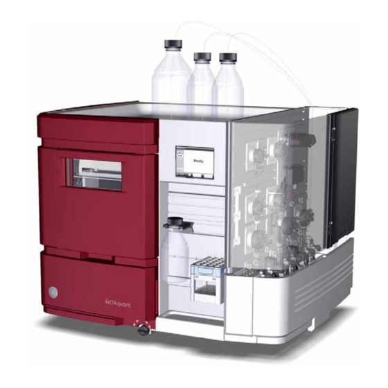
3 System description System description About this chapter This chapter gives an overview of the ÄKTA avant instrument, software and accessories. In this chapter This chapter contains the following sections: Section See page 3.1 ÄKTA avant instrument overview 3.2 UNICORN software Illustration of the system The following illustration shows the ÄKTA avant instrument with UNICORN software in- stalled on a computer. -
Page 37: Äkta Avant Instrument Overview
3 System description 3.1 ÄKTA avant instrument overview ÄKTA avant instrument overview Introduction This section shows an overview of the ÄKTA avant instrument. Technical details about the instrument and the individual modules are found in ÄKTA avant User Manual. Exterior design The ÄKTA avant instrument has a modular design, with all the liquid handling modules placed on the exterior of the instrument. - Page 38 3 System description 3.1 ÄKTA avant instrument overview Illustration of the main parts of the instrument The following illustration shows the location of the main parts of the instrument. Part Function Part Function Fraction collector Buffer tray Instrument display Wet side Foldable door Pump cover Holder rails...
- Page 39 3 System description 3.1 ÄKTA avant instrument overview Illustration of the wet side modules of the instrument The following illustration shows the modules of the wet side of the instrument. Part Function Part Function Injection valve Flow restrictor pH valve Column valve UV monitor Conductivity monitor...
- Page 40 3 System description 3.1 ÄKTA avant instrument overview Available modules The ÄKTA avant instrument is always delivered with the standard modules installed, but one or more optional modules may be added to the flow path. The following tables contains information on the standard modules and the optional modules of the ÄKTA avant 25 and ÄKTA avant 150 instruments.
- Page 41 3 System description 3.1 ÄKTA avant instrument overview Optional modules Module Label in ÄKTA avant 25 ÄKTA avant 150 Second Inlet valve A V9-A2 V9H-A2 Second Inlet valve B V9-B2 V9H-B2 Extra Inlet valve X1 V9-IX V9H-IX Extra Inlet valve X2 V9-IX V9H-IX Second Sample inlet valve...
- Page 42 3 System description 3.1 ÄKTA avant instrument overview Module Description Sample pump P9-S or P9H S A high precision pump which delivers sample or buffer in purification runs. Pressure monitor R9 Pressure monitor which reads the system pressure after System Pump A and System Pump B. Pump flow restrictor Prevents the system from siphoning when the flow path after the pump is open.
- Page 43 3 System description 3.1 ÄKTA avant instrument overview Module Description Column valve V9-C or V9H-C Column valve which connects up to five columns to the instrument, and directs the flow to one column at a time. The column valve features two integrated pressure sensors.
- Page 44 3 System description 3.1 ÄKTA avant instrument overview Module Description Second Inlet valve B V9-B2 Second inlet valves for System pump B, to extend the or V9H-B2 number of inlets up to 14. Inlet valve X1 and Inlet Inlet valve with eight inlet ports. No integrated air sensor. valve X2 V9-IX or V9H-IX Second Sample inlet valve Second inlet valve for Sample pump to extend the...
- Page 45 3 System description 3.1 ÄKTA avant instrument overview Illustration of the instrument display The following illustration shows the instrument display with the system state Ready showing. Instrument display indicators and buttons The instrument display is a touchscreen that shows the current system status. The in- strument display includes the following indicators and buttons Indicator/Button Description...
-
Page 46: Unicorn Software
3 System description 3.2 UNICORN software UNICORN software Introduction This section gives an overview of the UNICORN software. It also describes the System Control module. To learn more about System Control and the other three modules Administration, Method Editor and Evaluation, see the UNICORN documentation package. In this section Section See page... -
Page 47: Unicorn Software Overview
3 System description 3.2 UNICORN software 3.2.1 UNICORN software overview 3.2.1 UNICORN software overview Introduction This section gives a brief overview of the UNICORN software: a complete package for control, supervision and evaluation of chromatography instruments and purification runs. From hereon, UNICORN refers to compatible versions of the software. The examples given in this manual are from UNICORN 6.4. - Page 48 3 System description 3.2 UNICORN software 3.2.1 UNICORN software overview When working with the modules Administration, Method Editor, System Control and Evaluation Classic it is possible to access descriptions of the active window by pressing the F1 key. This can be especially helpful when editing methods ÄKTA avant Operating Instructions 29101556 AB...
-
Page 49: The System Control Module
3 System description 3.2 UNICORN software 3.2.2 The System Control module 3.2.2 The System Control module Introduction The System Control module is used to start, view, and control a manual or method run. System Control panes As seen in the following illustration, three panes are shown in the System Control module by default. - Page 50 3 System description 3.2 UNICORN software 3.2.2 The System Control module System Control toolbar buttons The following table shows the System Control toolbar buttons that are referred to in this manual. Button Function Button Function Open Method Navigator. Run. Starts a method run. Opens the Method Naviga- tor where available meth- ods are listed.
-
Page 51: Installation
4 Installation Installation About this chapter This chapter provides the instructions necessary to enable users and service personnel to install the instrument and the software. Read the entire Installation chapter before starting to install the ÄKTA avant instrument. Note: For information on how to how to unpack the ÄKTA avant instrument and how to lift the instrument onto a laboratory bench see ÄKTA avant Unpacking In- structions. -
Page 52: Site Preparation
4 Installation 4.1 Site preparation Site preparation Introduction This section describes the site planning and the preparations necessary to perform before installation of an ÄKTA avant system. The purpose is to provide planners and technical staff with the data needed to prepare the laboratory for the installation. The laboratory site must be planned and prepared before installing the ÄKTA avant system. -
Page 53: Delivery And Storage
When you receive the delivery • Record on the receiving documents if there is any apparent damage on the delivery box. Inform your GE representative of such damage. • Move the delivery box to a protected location indoors. Delivery box ÄKTA avant instruments are shipped in a delivery box with the following dimensions and... - Page 54 4 Installation 4.1 Site preparation 4.1.1 Delivery and storage Equipment for transportation The following equipment is recommended for handling the delivery boxes: Equipment Specifications Pallet mover Suitable for a lightweight pallet 80 × 100 cm Cart for transporting the instru- Dimensioned to accommodate the size and weight ment to the lab of the instrument...
-
Page 55: Room Requirements
4 Installation 4.1 Site preparation 4.1.2 Room requirements 4.1.2 Room requirements Introduction This section describes the requirements for the transportation route and the room where the ÄKTA avant instrument is placed. WARNING Access to power switch and power cord with plug. Do not block access to the power switch and power cord. - Page 56 4 Installation 4.1 Site preparation 4.1.2 Room requirements Allow space on the laboratory bench for: • handling of samples and buffers (2 × 30 cm) • computer and monitor (80 cm) • access for service (see the following topic) Service access To access the rear panel, the instrument can be rotated on a swivel foot.
- Page 57 4 Installation 4.1 Site preparation 4.1.2 Room requirements Equipment dimensions The outer dimensions of the ÄKTA avant instrument are shown in the following illustration. 66 cm 71 cm 86 cm Equipment weight Item Weight ÄKTA avant instrument 116 kg Computer approximately 9 kg Monitor approximately 3 kg...
-
Page 58: Site Environment
4 Installation 4.1 Site preparation 4.1.3 Site environment 4.1.3 Site environment Introduction This section describes the environmental requirements for installation of the ÄKTA avant instrument. Environmental conditions The following general requirements must be fulfilled: • The room must have exhaust ventilation •... - Page 59 4 Installation 4.1 Site preparation 4.1.3 Site environment Heat output The heat output data is listed in the following table. Component Heat output ÄKTA avant instrument Typically 400 W Maximum 800 W Computer, incl. monitor and printer Typically 300 W Refer to manufacturer's instructions for more information.
-
Page 60: Power Requirements
4 Installation 4.1 Site preparation 4.1.4 Power requirements 4.1.4 Power requirements Introduction This section describes the electrical power requirements for the ÄKTA avant instrument. Electrical power requirements The following table specifies the power requirements. Parameter Requirement Supply voltage 100 to 240 V AC ±10% Frequency 50/60 Hz Transient overvoltages... -
Page 61: Computer Requirements
4 Installation 4.1 Site preparation 4.1.5 Computer requirements 4.1.5 Computer requirements Introduction ÄKTA avant systems are controlled by UNICORN software running on a PC. The PC can be part of the delivery or be supplied locally. The PC used must fulfill the recommendations stated in this section. General computer specifications For information about compatibility between UNICORN versions and the supported op- erating systems and database versions see the UNICORN compatibility matrix at... - Page 62 4 Installation 4.1 Site preparation 4.1.5 Computer requirements • UNICORN is not compatible with the Windows 7 feature High DPI Aware- ness, which allows the graphic user interface to be scaled. The interface scale must remain at 100% to avoid issues with clipping and misaligning of parts of the UNICORN user interface.
-
Page 63: Required Materials
4 Installation 4.1 Site preparation 4.1.6 Required materials 4.1.6 Required materials Introduction This section describes the accessories required for the installation and operation of the ÄKTA avant instrument. Buffers and solutions The buffers and solutions listed in the following table are required during the installation procedure and should be provided at the installation site. - Page 64 4 Installation 4.1 Site preparation 4.1.6 Required materials Fraction collector tubes and bottles The tubes and bottles used in the built-in fraction collector must fulfill the requirements listed in the following table. Examples of manufacturers are also listed in the table. Tube or bottle Diameter (mm) Height (mm)
- Page 65 4 Installation 4.1 Site preparation 4.1.6 Required materials Approved deep well plates The deep well plates listed in the table below are tested and approved by GE to be used with the built-in fraction collector. Plate type Manufacturer Part no.
-
Page 66: Hardware Installation
WARNING Power cord. Only use power cords with approved plugs delivered or approved by GE. WARNING Access to power switch and power cord with plug. Do not block access to the power switch and power cord. The power switch must always be easy to access. - Page 67 4 Installation 4.2 Hardware installation Section See page 4.2.6 Start the instrument and the computer ÄKTA avant Operating Instructions 29101556 AB...
-
Page 68: Install The Computer Equipment
4 Installation 4.2 Hardware installation 4.2.1 Install the computer equipment 4.2.1 Install the computer equipment Introduction The computer is supplied as a part of the ÄKTA avant delivery, or supplied locally. Unpacking and installing Unpack and install the computer according to the manufacturer's instructions. NOTICE Any computer used with the equipment must comply with IEC 60950 and be installed and used according to the manufacturer's... -
Page 69: Connect The System Units
ÄKTA avant instrument WARNING • Power cord. Only use power cords with approved plugs deliv- ered or approved by GE. • Supply voltage. Before connecting the power cord, make sure that the supply voltage at the wall outlet corresponds to the marking on the instrument. - Page 70 4 Installation 4.2 Hardware installation 4.2.2 Connect the system units Part Function Power input connector Network connector (Ethernet) UniNet-9 connectors Note: Termination plugs must be connected to the connectors that are not in use. Other connectors are for use by authorized service engineers only. NOTICE Misuse of UniNet-9 connectors.
- Page 71 4 Installation 4.2 Hardware installation 4.2.2 Connect the system units Connect power to the ÄKTA avant instrument Follow the instructions to connect power to the ÄKTA avant instrument. Step Action Select the correct power cord to be used. Each instrument is delivered with 2 alternative power cords: Power cord with US-plug, 2 m •...
- Page 72 Note: If the computer has not been supplied by GE and if network configuration is to be used, see UNICORN Administration and Technical Manual for further information on network settings.
-
Page 73: Prepare Waste Tubing
4 Installation 4.2 Hardware installation 4.2.3 Prepare waste tubing 4.2.3 Prepare waste tubing Location of waste tubing All waste tubing is found on the rear of the instrument, see the following illustration. Part Description Waste tubing from the injection valve, the pH valve and the outlet valve (pieces of tubing marked W, W1, W2 and W3). - Page 74 4 Installation 4.2 Hardware installation 4.2.3 Prepare waste tubing Prepare the waste tubing Follow the instructions to prepare the waste tubing. Step Action Place the four pieces of waste tubing from the injection valve, the pH valve and the outlet valve (pieces of tubing marked W, W1, W2 and W3) in a vessel placed below the bench.
- Page 75 4 Installation 4.2 Hardware installation 4.2.3 Prepare waste tubing Note: If the tubing is too short, replace it with new tubing. Do not lengthen the tubing as this might cause obstruction of the tubing and flooding in the fraction col- lector chamber.
-
Page 76: Install The Barcode Scanner 2-D And The Ph Electrode
4 Installation 4.2 Hardware installation 4.2.4 Install the Barcode Scanner 2-D and the pH electrode 4.2.4 Install the Barcode Scanner 2-D and the pH electrode Introduction This section describes how to install the Barcode Scanner 2-D and the pH electrode. Install the barcode scanner Connect the cable of the Barcode Scanner 2-D to the scanner head and to a USB port on the computer. -
Page 77: Prepare The Pump Rinsing System
4 Installation 4.2 Hardware installation 4.2.5 Prepare the pump rinsing system 4.2.5 Prepare the pump rinsing system Illustration of the pump piston rinsing systems Part Description Inlet tubing to the sample pump piston rinsing system Outlet tubing from the sample pump piston rinsing system Inlet tubing to the system pump piston rinsing system Outlet tubing from the system pump piston rinsing system ÄKTA avant Operating Instructions 29101556 AB... - Page 78 4 Installation 4.2 Hardware installation 4.2.5 Prepare the pump rinsing system Prime the pump piston rinsing system Follow the instructions to fill the pump piston rinsing systems with rinsing solution. See the tubing configuration of the rinsing systems in Illustration of the pump piston rinsing systems, on page Step Action...
- Page 79 4 Installation 4.2 Hardware installation 4.2.5 Prepare the pump rinsing system Step Action Connect a 25 to 30 ml syringe to the outlet tubing of the system pump piston rinsing system. Draw liquid slowly into the syringe. Disconnect the syringe and discard its contents. Immerse the outlet tubing in the rinsing solution tube where the inlet tubing of the system pump piston rinsing system is immersed.
-
Page 80: Start The Instrument And The Computer
4 Installation 4.2 Hardware installation 4.2.6 Start the instrument and the computer 4.2.6 Start the instrument and the computer Introduction This section describes how to start the instrument and the computer. Instruction Follow the instructions to start the instrument and the computer. Step Action Switch on the instrument by pressing the Power switch to the I position. -
Page 81: Software Installation
4 Installation 4.3 Software installation Software installation Introduction This section gives an overview of the different UNICORN installation types. The software should be installed by an assigned UNICORN system administrator. Detailed information about software installation and configuration is available in the UNICORN Administration and Technical Manual. -
Page 82: Start Unicorn And Connect To System
4 Installation 4.4 Start UNICORN and connect to system Start UNICORN and connect to system Introduction This section describes how to start and log on to UNICORN and how to connect the in- strument to UNICORN. Prerequisites UNICORN must be correctly installed according to instructions in the UNICORN Administration and Technical Manual. - Page 83 4 Installation 4.4 Start UNICORN and connect to system Step Action In the Log On dialog box: select User Name • enter Password. • Note: It is also possible to select the Use Windows Authentication checkbox and enter a network ID in the User Name field. click OK.
- Page 84 4 Installation 4.4 Start UNICORN and connect to system Step Action In the System Control module, click the Connect to Systems button. Result: The Connect to Systems dialog box opens. In the Connect to Systems dialog box: Select a system check box. •...
-
Page 85: Prime Inlets And Purge Pump Heads
4 Installation 4.5 Prime inlets and purge pump heads Prime inlets and purge pump heads About this section Before using the sample pump or system pumps it is important to do the following: • Prime the inlets (fill the inlets with liquid). •... -
Page 86: Prime Buffer Inlets And Purge System Pumps
4 Installation 4.5 Prime inlets and purge pump heads 4.5.1 Prime buffer inlets and purge system pumps 4.5.1 Prime buffer inlets and purge system pumps Overview The procedure consists of the following stages: Stage Description Prime all inlet tubing to be used during the run. Validate priming of inlet tubing. - Page 87 4 Installation 4.5 Prime inlets and purge pump heads 4.5.1 Prime buffer inlets and purge system pumps Step Action In the Process Picture: Click the inlet valve icons. (Click both the Inlet A and Inlet B icons, one • at a time, if both inlets are to be primed.) Click the position of the inlet to be filled.
- Page 88 4 Installation 4.5 Prime inlets and purge pump heads 4.5.1 Prime buffer inlets and purge system pumps Step Action Check that there is no air left in the pump by following the instructions in Validate prime or purge of System Pump A or B or Sample Pump, on page If air bubbles are indicated, follow the instructions in Purge System Pump B, on page 88...
- Page 89 4 Installation 4.5 Prime inlets and purge pump heads 4.5.1 Prime buffer inlets and purge system pumps Step Action In the Process Picture: Click the Inlet valve B icon. • Click the position of one of the inlets that will be used at the beginning •...
- Page 90 4 Installation 4.5 Prime inlets and purge pump heads 4.5.1 Prime buffer inlets and purge system pumps Step Action Connect a 25 to 30 ml syringe to the purge valve of the left pump head of System Pump B. Make sure that the syringe fits tightly into the purge con- nector.
- Page 91 4 Installation 4.5 Prime inlets and purge pump heads 4.5.1 Prime buffer inlets and purge system pumps Purge System Pump A Purge both pump heads of System Pump A by following the same procedure as in Purge System Pump B, on page 88, but replace step 3 and 4 with the following: Step Action...
- Page 92 4 Installation 4.5 Prime inlets and purge pump heads 4.5.1 Prime buffer inlets and purge system pumps Validate prime or purge of System Pump A or B or Sample Pump Follow these instructions to check that there is no air left in the pump after performing a prime or a purge.
-
Page 93: Prime Sample Inlets And Purge Sample Pump
4 Installation 4.5 Prime inlets and purge pump heads 4.5.2 Prime sample inlets and purge Sample Pump 4.5.2 Prime sample inlets and purge Sample Pump Overview The procedure consists of the following stages: Stage Description Prime all sample inlet tubing to be used during the run. Validate priming of inlet tubing. - Page 94 4 Installation 4.5 Prime inlets and purge pump heads 4.5.2 Prime sample inlets and purge Sample Pump Step Action In the Process Picture Click the Sample inlet valve icon. • Select the position of the inlet to be filled. Start at the inlet position with •...
- Page 95 4 Installation 4.5 Prime inlets and purge pump heads 4.5.2 Prime sample inlets and purge Sample Pump Step Action Check that there is no air left in the pump by following the instructions in Validate prime or purge of System Pump A or B or Sample Pump, on page If air bubbles are indicated, follow the instructions in Purge Sample Pump, on page...
- Page 96 4 Installation 4.5 Prime inlets and purge pump heads 4.5.2 Prime sample inlets and purge Sample Pump Step Action In the Process Picture: Click the Sample inlet icon, then click Buffer. • Click the Sample pump icon: Set the Sample flow to 1.0 ml/min for ÄKTA •...
- Page 97 4 Installation 4.5 Prime inlets and purge pump heads 4.5.2 Prime sample inlets and purge Sample Pump Step Action Connect the syringe to the right purge valve on the sample pump, and repeat step 6 to 8. Check that there is no air left in the pump by following the instructions in Validate prime or purge of System Pump A or B or Sample Pump, on page End the run Click the End button in the System Control toolbar to end the run.
-
Page 98: Prime Q Inlets
4 Installation 4.5 Prime inlets and purge pump heads 4.5.3 Prime Q inlets 4.5.3 Prime Q inlets Overview The procedure consists of the following stages: Stage Description Prime all Q inlet tubing. Validate priming of Q inlet tubing. Purge Quaternary Valve and the system pumps if pressure signal indicates air bubbles. - Page 99 4 Installation 4.5 Prime inlets and purge pump heads 4.5.3 Prime Q inlets Step Action Connect a 25 to 30 ml syringe to one of the purge valves of either of the system pumps. Make sure that the syringe fits tightly into the purge connec- tor.
- Page 100 4 Installation 4.5 Prime inlets and purge pump heads 4.5.3 Prime Q inlets Purge Quaternary Valve and the system pumps If the priming was done thoroughly and the final buffer was drawn all the way into the syringe and the validation of the priming showed that there was no air left in the pump it is not necessary to purge Quaternary Valve and the system pumps.
- Page 101 4 Installation 4.5 Prime inlets and purge pump heads 4.5.3 Prime Q inlets Step Action Connect a 25 to 30 ml syringe to the left purge valve of the selected system pump. Make sure that the syringe fits tightly into the purge connector. Open the purge valve by turning it counterclockwise about 3 quarters of a turn.
-
Page 102: Performance Tests
4 Installation 4.6 Performance tests Performance tests Introduction Before taking the ÄKTA avant instrument into use, run performance tests to check the function of the equipment. See ÄKTA avant User Manual for further instructions. ÄKTA avant Operating Instructions 29101556 AB... -
Page 103: Prepare The System For A Run
5 Prepare the system for a run Prepare the system for a run About this chapter This chapter describes the preparations necessary before starting a run. In this chapter This chapter contains the following sections: Section See page 5.1 Before you prepare the system 5.2 Prepare the flowpath 5.3 Prime buffer inlets and purge system pumps 5.4 Connect a column... -
Page 104: Before You Prepare The System
5 Prepare the system for a run 5.1 Before you prepare the system Before you prepare the system Introduction It is important to prepare the system in accordance with the settings in the method to be run. Before preparing the system, verify the settings in the Method Editor and make sure that all accessories to be used are available. - Page 105 5 Prepare the system for a run 5.1 Before you prepare the system WARNING When using flammable liquids with the ÄKTA avant instrument, follow these precautions to avoid any risk of fire or explosion. • Fraction collector. Do not fractionate flammable liquids in the built-in fraction collector.
-
Page 106: Prepare The Flowpath
5 Prepare the system for a run 5.2 Prepare the flowpath Prepare the flowpath Introduction The flow path contains tubing, valves, pumps and monitors. This section gives an overview of the flow path and describes how to prepare the flow path before a run. CAUTION •... - Page 107 5 Prepare the system for a run 5.2 Prepare the flowpath Illustration of the flow path The following illustration shows an overview of the standard flow path. Part Description Pressure monitor Sample pump Sample inlet valve Quaternary valve Inlet valve A Inlet valve B System pump B ÄKTA avant Operating Instructions 29101556 AB...
- Page 108 5 Prepare the system for a run 5.2 Prepare the flowpath Part Description System pump A Pressure monitor Mixer Injection valve Sample loop or Superloop Column valve Column UV monitor Conductivity monitor Flow restrictor pH valve with pH monitor Outlet valve Fraction collector Prepare the inlet tubing Connect inlet tubing to the inlet ports that are to be used, and immerse all inlet tubing...
- Page 109 5 Prepare the system for a run 5.2 Prepare the flowpath Waste ports The following table shows the waste ports of Injection Valve, pH Valve and Outlet Valve. Valves and ports Illustrations Injection Valve (label V9- Inj and V9H-Inj) Waste ports: W1, W2 •...
- Page 110 5 Prepare the system for a run 5.2 Prepare the flowpath Prepare the waste tubing Make sure that the waste tubing is prepared according to the instructions in Section 4.2.3 Prepare waste tubing, on page Prepare the outlet tubing Connect outlet tubing to the outlet ports of the outlet valve that are to be used during the run.
-
Page 111: Prime Buffer Inlets And Purge System Pumps
5 Prepare the system for a run 5.3 Prime buffer inlets and purge system pumps Prime buffer inlets and purge system pumps Introduction Before you start the system pumps, it is important to do the following: • Prime the inlets (fill the buffer inlets with liquid). •... -
Page 112: Connect A Column
5 Prepare the system for a run 5.4 Connect a column Connect a column Introduction This section describes how to connect a column to the instrument using a column holder and without introducing air into the flow path. Several types of column holders are available for the ÄKTA avant instrumen, see ÄKTA avant User Manual. - Page 113 5 Prepare the system for a run 5.4 Connect a column Attach a column holder and connect a column Follow the instructions to connect a column to the instrument. Always use a column holder. The column is connected to two opposite parts of the column valve, using appro- priate tubing and connectors.
- Page 114 5 Prepare the system for a run 5.4 Connect a column Step Action Connect a suitable tubing to a column valve port, for example port 1A if column position 1 was chosen in the method to be run. In the Process Picture: Click the Column valve icon.
- Page 115 5 Prepare the system for a run 5.4 Connect a column Step Action In the Process Picture: Click the System pumps icon. • Enter a low System flow (e.g., 0.2 ml/min). • Click Set flow rate. • Result: A system flow of 0.2 ml/min starts. When buffer leaves the tubing on port 1A (if port 1A was chosen in the method to be run) in a continuous mode and the top part of the column is filled with buffer, connect the tubing to the top of the column.
- Page 116 5 Prepare the system for a run 5.4 Connect a column Step Action Connect a piece of tubing to the bottom of the column. When buffer leaves the tubing at the bottom of the column in a continuous mode, connect this piece of tubing to the column valve. Use the port opposite to the one already connected to the column, in this example port 2B.
-
Page 117: Set Pressure Alarms
5 Prepare the system for a run 5.5 Set pressure alarms Set pressure alarms Introduction The columns can be protected by two different types of pressure alarms: • The pre-column pressure alarm protects the column hardware. • The delta-column pressure alarm protects the column media. The column valves V9-C and V9H-C have built-in pressure sensors that automatically measure the pre-column and delta-column pressure. - Page 118 5 Prepare the system for a run 5.5 Set pressure alarms Step Action In the System Control module, on the Manual menu, click Execute Manual Instructions . Result: The Manual instructions dialog box opens. In the Instructions box, select Alarms:Alarm pre column pressure. Click Enabled in the Mode field.
-
Page 119: Calibrate The Ph Monitor
5 Prepare the system for a run 5.6 Calibrate the pH monitor Calibrate the pH monitor Introduction If pH will be measured during the chromatographic run, the pH monitor should be cali- brated before the run is started. Use two pH calibration buffers with a difference of at least one pH unit. - Page 120 5 Prepare the system for a run 5.6 Calibrate the pH monitor Step Action Enter the pH of the first pH standard buffer in the pH for buffer 1 box. Fill a syringe with approximately 10 ml of the first pH standard buffer. Con- nect the syringe to the Luer connector in pH valve port Cal, and inject the buffer.
-
Page 121: Prepare The Built-In Fraction Collector
5 Prepare the system for a run 5.7 Prepare the built-in fraction collector Prepare the built-in fraction collector Introduction This section describes how to prepare the built-in fraction collector. For detailed informa- tion regarding the types of deep well plates, tubes and cassettes, see ÄKTA avant User Manual. - Page 122 5 Prepare the system for a run 5.7 Prepare the built-in fraction collector Workflow for preparing the built-in fraction collector Before starting to prepare the built-in fraction collector, check the fractionation settings in the method to be run. Perform the steps described below according to the settings in the method.
- Page 123 5 Prepare the system for a run 5.7 Prepare the built-in fraction collector Step Action Place the tubes and deep well plates in the cassettes. Make sure that the deep well plates are rotated so that the well marked A1 is positioned above the A1 marking on the cassette.
- Page 124 Action Place the cassettes on the cassette tray. Make sure that the cassette type code (see the illustration) faces the front of the tray marked with the GE monogram. Open the fraction collector drawer by pressing the handle upwards, and pulling out the drawer.
- Page 125 Action Place the cassette tray on the tray support of the fraction collector drawer. Make sure that the front of the tray (marked with the GE monogram) faces the front of the drawer and is hooked onto the two pins.
- Page 126 Place the rack on the tray support of the fraction collector drawer. Make sure that the front of the rack (marked with the GE monogram) faces the front of the drawer and is hooked onto the two pins.
- Page 127 5 Prepare the system for a run 5.7 Prepare the built-in fraction collector Cassette and tray identification When the door of the fraction collector is closed automatic scanning is performed. There are two types of scanning procedures: • Full scan: Scanning of cassette type codes to determine which types of cassettes are used, and scanning of rows and columns in deep well plates to identify which types of plates are used (24, 48, or 96 wells).
-
Page 128: Prepare For A Run At Cold Temperature
5 Prepare the system for a run 5.8 Prepare for a run at cold temperature Prepare for a run at cold temperature Introduction To fit the ÄKTA avant instrument in a cold cabinet, the foldable door and pump cover can be removed. For instructions, see ÄKTA avant User Manual. When using the instrument in a cold room or cold cabinet, make sure to follow the precautions listed in the next topic. -
Page 129: Run A Method
6 Run a method Run a method About this chapter This chapter describes how to start up and run a method, and also how to handle the system after the run. In this chapter This chapter contains the following sections: Section See page 6.1 Before you start... -
Page 130: Before You Start
6 Run a method 6.1 Before you start Before you start Introduction Before starting a run, it is necessary to read and understand the information in this section and to perform the checks listed in the next topic. WARNING • Always use appropriate Personal Protective Equipment (PPE) during operation and maintenance of this product. - Page 131 6 Run a method 6.1 Before you start Warnings concerning use of hazardous substances WARNING • Hazardous chemicals during run. When using hazardous chemicals, run System CIP and Column CIP to flush the entire system tubing with distilled water, before service and mainte- nance.
- Page 132 6 Run a method 6.1 Before you start If you want to... then... resume, for example, a held or paused click the Continue button. method run. Note: An ended method cannot be continued. permanently end the run click the End button. Note: When ending a method run in advance, it is possible to save the partial result.
-
Page 133: Applying The Sample
6 Run a method 6.2 Applying the sample Applying the sample Introduction A number of different sample application techniques are available. The sample can be applied either directly onto the column using the sample pump, or via a loop. A loop can be filled either manually or by using the sample pump. - Page 134 6 Run a method 6.2 Applying the sample Step Action Connect the syringe to the Injection Valve port Syr. Load sample into the sample loop. To avoid sample loss due to siphoning, leave the syringe in the port until the sample has been injected onto the column during the run.
- Page 135 6 Run a method 6.2 Applying the sample Tip: Empty the sample loop with a buffer volume that exceeds the volume of the loop. This will ensure that the loop is completely emptied. ÄKTA avant Operating Instructions 29101556 AB...
-
Page 136: Start A Method Run
6 Run a method 6.3 Start a method run Start a method run Introduction This section describes how to start a run using a previously created method. If Column Logbook was enabled during installation of the software, registration and selection of individual columns is possible at method start. - Page 137 6 Run a method 6.3 Start a method run Step Action Click Start on the last page of the Start Protocol. Result: If column logging was chosen at installation of UNICORN and a column • type was selected at method creation, the Select Columns dialog box opens.
- Page 138 6 Run a method 6.3 Start a method run Register a column and start a The following instructions describe how to register a column and start a run. Step Action Is the column to be used already registered? If No, continue to step 2. •...
- Page 139 6 Run a method 6.3 Start a method run Step Action Register the column using the Barcode Scanner 2-D as follows: Make sure that the pointer is placed in the first position of the Code box. • Point the Barcode Scanner 2-D towards the data matrix tag on the col- •...
- Page 140 6 Run a method 6.3 Start a method run Step Action In the expanded New Column dialog box: Enter an column alias in the Alias box (optional). • Click a chromatography technique on the Technique menu. • Click a column type on the Column type menu. •...
- Page 141 6 Run a method 6.3 Start a method run Step Action In the Select Columns dialog box: Click Enter ID. • Use the Barcode Scanner 2-D (see step 3) to enter the column ID. • Alternatively, click Select ID and click the column individual to be used •...
-
Page 142: Monitor The Run
6 Run a method 6.4 Monitor the run Monitor the run Introduction You may follow the on-going method run in the System Control module. The current system status is shown in the System state panel in the Run Data pane. For example, it may state Run, Wash or Hold. - Page 143 6 Run a method 6.4 Monitor the run Process Picture The Process Picture displays the current flow path, run parameters and real-time data from monitors during a run. It also allows manual interactions with the system. Tubing colors indicate flow path states, as shown in the following illustration and de- scribed in the following table.
- Page 144 6 Run a method 6.4 Monitor the run Actions in the Process Picture pane It is possible to interact with the Process Picture pane. • To open a related instruction, click the component icon. The example below shows the pop-up toolbar for the Injection valve icon. Instructions can be given from the pop-up toolbar of each component icon.
-
Page 145: After Run Procedures
6 Run a method 6.5 After run procedures After run procedures Introduction This section describes how to clean the instrument and columns after a chromatographic run, and how to prepare the system for storage. The instrument and the columns should be cleaned between the runs. This will prevent, for example, sample contamination, protein precipitation and column clogging. - Page 146 6 Run a method 6.5 After run procedures System storage If the instrument is not going to be used for a couple of days or longer, also perform the following: • Fill the system and inlets with storage solution (e.g., 20% ethanol) using the System CIP method.
- Page 147 6 Run a method 6.5 After run procedures Log off or exit UNICORN Follow the instructions to log off or exit UNICORN. This can be performed from any of the UNICORN modules. If you want to... then... log off UNICORN on the File menu, click Log off.
-
Page 148: Maintenance
7 Maintenance Maintenance About this chapter Regular maintenance is essential for reliable function and results. This chapter provides schedules for preventive maintenance that should be performed by the user of the ÄKTA avant instrument. Instructions for replacing pump parts and cleaning pump head check valves are included in this chapter. -
Page 149: Maintenance Program
Maintenance when required WARNING Electrical shock hazard. All repairs should be done by service personnel authorized by GE. Do not open any covers or replace parts unless specifically stated in the user documentation. Periodic maintenance program The following periodic maintenance should be performed by the user of the ÄKTA avant instrument. -
Page 150: 7.2 Replace Pump Piston Seal, O-Rings, And Rinse Membrane Of Pump P9 Or Pump
7 Maintenance 7.1 Maintenance program Maintenance when required The following maintenance should be performed by the user of the ÄKTA avant instrument when required. Refer to the ÄKTA avant User Manual for detailed instructions. Maintenance action Clean the instrument externally Run System CIP (System cleaning-in-place) Run Column CIP (Column cleaning-in-place) Clean the fraction collector... - Page 151 7 Maintenance 7.1 Maintenance program Maintenance action Replace pump rinsing system tubing Replace valve modules ÄKTA avant Operating Instructions 29101556 AB...
-
Page 152: Replace Pump Piston Seal, O-Rings, And Rinse Membrane Of Pump P9 Or Pump P9H
7 Maintenance 7.2 Replace pump piston seal, O-rings, and rinse membrane of Pump P9 or Pump P9H Replace pump piston seal, O-rings, and rinse mem- brane of Pump P9 or Pump P9H Introduction Follow the instructions to replace the O-rings, piston seal, and rinse membrane of pumps P9, P9H A, P9H B, or P9H S. - Page 153 7 Maintenance 7.2 Replace pump piston seal, O-rings, and rinse membrane of Pump P9 or Pump P9H Required material The following materials are required: • Adjustable wrench • For Pump P9: Star screwdriver, T20 • For Pump P9H: Star screwdriver, T10 and T20 •...
- Page 154 7 Maintenance 7.2 Replace pump piston seal, O-rings, and rinse membrane of Pump P9 or Pump P9H Pump P9H Part Description Part Description Piston Piston seal Return spring Outlet check valve Pump membrane housing O-ring Star screws Purge valve O-ring Star screws Support washer Inlet check valve...
- Page 155 7 Maintenance 7.2 Replace pump piston seal, O-rings, and rinse membrane of Pump P9 or Pump P9H Step Action Unscrew the two white plastic screws located below each pump head by hand. Pull the plastic connectors to the sides to release the inlet manifold. Disconnect the tubing of the pump piston rinsing system.
- Page 156 7 Maintenance 7.2 Replace pump piston seal, O-rings, and rinse membrane of Pump P9 or Pump P9H Step Action Place the front section of the pump head face down on the bench. For Pump P9, unscrew the two screws of the support washer using a star screwdriver, T20.
- Page 157 7 Maintenance 7.2 Replace pump piston seal, O-rings, and rinse membrane of Pump P9 or Pump P9H Step Action Carefully pull off the pump membrane housing together with the piston and return spring. Inspect the piston and return spring for signs of damage. If damaged, discard the piston and return spring and use a new piston and return spring when assembling the pump head.
- Page 158 7 Maintenance 7.2 Replace pump piston seal, O-rings, and rinse membrane of Pump P9 or Pump P9H Replace O-rings, piston seal and pump membrane housing Step Action Unscrew the purge valve of the pump head. Replace the O-ring on the purge valve with a new O-ring, and screw the purge valve back into the pump head.
- Page 159 7 Maintenance 7.2 Replace pump piston seal, O-rings, and rinse membrane of Pump P9 or Pump P9H Step Action Place the support washer on top of the new seal in the front section of the pump head. Screw the two or four screws of the support washer. Make sure to tighten the screws fully.
- Page 160 7 Maintenance 7.2 Replace pump piston seal, O-rings, and rinse membrane of Pump P9 or Pump P9H Assemble the pump head Make sure to assemble the pump head correctly. Refer to Illustrations, on page 153. Step Action Insert the piston into the return spring. Insert piston and return spring into hole in the pump module.
- Page 161 7 Maintenance 7.2 Replace pump piston seal, O-rings, and rinse membrane of Pump P9 or Pump P9H Step Action For Pump P9: Connect the reference capillary Ref 2 (or an equivalent • capillary that gives a backpressure of 6 to 8 MPa [60 to 80 bar]) to one of the column positions of the column valve (e.g., ports 1A and 1B).
- Page 162 7 Maintenance 7.2 Replace pump piston seal, O-rings, and rinse membrane of Pump P9 or Pump P9H Step Action Run the flow for 2 hours. Discard the used buffer. ÄKTA avant Operating Instructions 29101556 AB...
-
Page 163: Replace Pump Piston Seal, O-Ring, And Rinse Membrane Of Pump P9-S
7 Maintenance 7.3 Replace pump piston seal, O-ring, and rinse membrane of Pump P9-S Replace pump piston seal, O-ring, and rinse mem- brane of Pump P9-S Introduction Follow the instructions to replace the O-ring, piston seal, and rinse membrane of Pump P9-S. - Page 164 7 Maintenance 7.3 Replace pump piston seal, O-ring, and rinse membrane of Pump P9-S Required material The following materials are required: • Adjustable wrench • Star screwdriver, T20 • Cross-headed screwdriver • Hex wrench • Ultrasonic bath • Ethanol, 20% •...
-
Page 165: Unscrew The Two White Plastic Screws Located Below Each Pump Head By Hand. Pull The Plastic Connectors To The Sides To Release The Inlet Manifold
7 Maintenance 7.3 Replace pump piston seal, O-ring, and rinse membrane of Pump P9-S Disassemble the pump head Step Action Make sure that no run is in progress on the instrument. Disconnect the tubing from the pump head, and disconnect the pump inlet tubing. - Page 166 7 Maintenance 7.3 Replace pump piston seal, O-ring, and rinse membrane of Pump P9-S Step Action Place the pump head face down on the bench. Pull out the piston together with the return spring. Inspect the piston and return spring for sign of damage. If damaged, discard the piston and return spring and use a new piston and return spring when assembling the pump head.
- Page 167 7 Maintenance 7.3 Replace pump piston seal, O-ring, and rinse membrane of Pump P9-S Step Action Lift off the rinse chamber. Gently pull off the piston seal. Discard the used seal. Clean the pump head, rinse chamber and drain plate in an ultrasonic bath. If there are particles on any surfaces, the check valves should be removed and cleaned separately, see Section 7.5 Clean pump head check valves, on...
- Page 168 7 Maintenance 7.3 Replace pump piston seal, O-ring, and rinse membrane of Pump P9-S Step Action Wet a new seal with 20% ethanol. Place the new seal in the hole in the front section of the pump head and press it into position. With the pump head facing downwards on the bench, place the rinse chamber onto the front section of the pump head with the rinse ports in line with the check valves.
- Page 169 7 Maintenance 7.3 Replace pump piston seal, O-ring, and rinse membrane of Pump P9-S Step Action Wipe clean the piston and remove all finger prints. Wet the piston with 20% ethanol, and insert the piston into the return spring. With the pump head facing downwards on the bench, insert the piston into the pump head by pushing it gently but firmly vertically downwards into the seal.
- Page 170 7 Maintenance 7.3 Replace pump piston seal, O-ring, and rinse membrane of Pump P9-S Step Action In the Manual instructions dialog: Select Flow path:Column position, and select the Position of the capillary • connected to the column valve. Click Insert. Select Flow path:Sample inlet and select a Position.
-
Page 171: Replace Pump Pistons
7 Maintenance 7.4 Replace pump pistons Replace pump pistons Introduction Follow the instructions to replace the pump pistons of the pumps P9, P9H and P9-S. Note: Always replace the O-rings, piston seals, and rinse membranes of both pump heads of a pump at the same time. NOTICE •... - Page 172 7 Maintenance 7.4 Replace pump pistons Replace pump pistons of Pump P9 and P9H If a damaged piston has been in operation, the piston seal will be destroyed and should also be replaced. To replace the piston and the seal of a system pump, see Section 7.2 Replace pump piston seal, O-rings, and rinse membrane of Pump P9 or Pump P9H, on page...
-
Page 173: Clean Pump Head Check Valves
7 Maintenance 7.5 Clean pump head check valves Clean pump head check valves Introduction Clean the check valves when required, for example if particles like dust or salt crystals in the check valve cause irregular or low flow. The cleaning procedure is the same for the system pumps and the sample pump. - Page 174 7 Maintenance 7.5 Clean pump head check valves Step Action Unscrew the purge valve by turning it counter-clockwise, and lift off the metal ring. Unscrew the plastic nut of the upper check valve using an adjustable wrench, and gently lift off the upper check valve. Unscrew the two white plastic screws located below each pump head.
- Page 175 7 Maintenance 7.5 Clean pump head check valves Step Action Unscrew the lower check valve using an adjustable wrench. WARNING Hazardous substances. When using hazardous chemicals, take all suitable protective measures, such as wearing protective clothing, glasses and gloves re- sistant to the substances used.
-
Page 176: Cleaning Before Planned Service
7 Maintenance 7.6 Cleaning before planned service Cleaning before planned service Cleaning before planned maintenance/service To ensure the protection and safety of service personnel, all equipment and work areas must be clean and free of any hazardous contaminants before a Service Engineer starts maintenance work. -
Page 177: Reference Information
8 Reference Information Reference Information About this chapter This chapter lists the technical specifications of the ÄKTA avant instrument. The chapter also includes a chemical resistance guide. See also ÄKTA avant 25 Product Documentation and ÄKTA avant 150 Product Documentation for detailed technical specifications. In this chapter This chapter contains the following sections: Section... -
Page 178: System Specifications
8 Reference Information 8.1 System specifications System specifications Technical specifications Parameter Data System configuration Benchtop system, external computer Control system UNICORN™ 6.3.2 or later version Connection between PC and instrument Ethernet Dimensions (Length x Depth x Height) 860 x 710 x 660 mm Weight (excluding computer) 116 kg Power supply... - Page 179 8 Reference Information 8.1 System specifications Enviromental requirements Parameter Data Storage and transport temperature range -25°C to 60°C Chemical environment Section 8.2 Chemical resistance guide, on page 180. Operating temperature range 4°C to 35°C Relative humidity 20% to 95%, noncondensing Equipment noise level Equipment Acoustic noise...
-
Page 180: Chemical Resistance Guide
8 Reference Information 8.2 Chemical resistance guide Chemical resistance guide Introduction This section provides general information about biocompatibilty and detailed information about chemical resistance of the ÄKTA avant instrument. In this section Section See page 8.2.1 General information about biocompatibility and chemical resis- tance 8.2.2 Chemical resistance specifications ÄKTA avant Operating Instructions 29101556 AB... -
Page 181: General Information About Biocompatibility And Chemical Resistance
8 Reference Information 8.2 Chemical resistance guide 8.2.1 General information about biocompatibility and chemical resistance 8.2.1 General information about biocompatibility and chemical resistance Biocompatibility The ÄKTA avant instrument is designed for maximum biocompatibility, with biochemically inert flow paths constructed mainly from titanium, PEEK and highly resistant fluoropoly- mers and fluoroelastomers. - Page 182 8 Reference Information 8.2 Chemical resistance guide 8.2.1 General information about biocompatibility and chemical resistance • Room temperature and limited overpressure is assumed. Note: Chemical influences are time and pressure dependent. Unless otherwise stated, all concentrations are 100%. ÄKTA avant Operating Instructions 29101556 AB...
-
Page 183: Chemical Resistance Specifications
This section provides detailed information about chemical resistance of the ÄKTA avant instrument to some of the most commonly used chemicals in liquid chromatography. Regarding exposure to solutions not covered by this information, contact your GE repre- sentative for recommendations. - Page 184 8 Reference Information 8.2 Chemical resistance guide 8.2.2 Chemical resistance specifications Chemical Concentra- CAS no/EC no tion Sodium hydroxide/ethanol 1 M/40% Sodium chloride 7647-14-5/ 231-598-3 Sodium hypochlorite 7681-52-9/231-668-3 If hydrochloric acid, HCl, is used as a cleaning agent when columns are connected to the system, the HCl concentration should not exceed 0.1 M in the pressure sensors.
- Page 185 8 Reference Information 8.2 Chemical resistance guide 8.2.2 Chemical resistance specifications Chemical Concentra- CAS no/EC no tion Acetonitrile/water/Trifluo- Max 0.2% roacetic acid (TFA) Ethanol 100% 75-08-1/ 200-837-3 Isopropanol 100% 67-63-0/ 200-661-7 Methanol 100% 74-93-1/ 200-659-6 Water/organic mobile Max 5% phase/formic acid formic acid Organic solvents can penetrate weaknesses in PEEK tubing walls more easily than water based buffers.
- Page 186 8 Reference Information 8.2 Chemical resistance guide 8.2.2 Chemical resistance specifications Reducing agents and other additives The following chemicals are suitable for continuous use. Chemical Concentra- CAS no/EC no tion Arginine 74-79-3/ 200-811-1 Benzyl alcohol 100-51-6/ 202-859-9 Dithioerythritol (DTE) 100 mM 3483-12-3 / 222-468-7 Dithiothreitol (DTT) 100 mM...
-
Page 187: Ordering Information
8 Reference Information 8.3 Ordering information Ordering information Introduction This chapter lists accessories and user replaceable spare parts available for ÄKTA avant. Tubing Item Code no. Reference capillary 1 28950749 Reference capillary 2 28950750 ETFE Tubing kit 10×1.0 m, id 1.0 mm, od 1/16″ 28980995 Note: Outlet tubing for ÄKTA avant 25. - Page 188 8 Reference Information 8.3 Ordering information Item Code no. Inlet/outlet tubing tag kit, ÄKTA avant 25 28981001 Note: Tags for all inlet and outlet tubing in ÄKTA avant 25. Inlet/outlet tubing tag kit, ÄKTA avant 150 28981004 Note: Tags for all inlet and outlet tubing in ÄKTA avant 150. Union 1/16″...
- Page 189 8 Reference Information 8.3 Ordering information Item Product code Ferrule for 1/16" tubing connector, blue 18112706 Ferrule for 1/8" tubing connector, yellow 18112118 Ferrule for 3/16" tubing connector, blue 18111248 Stop plug, 5/16" male 18111250 Stop plug, 1/16" male 18111252 Holders Item Code no.
- Page 190 8 Reference Information 8.3 Ordering information Conversion kits Item Code no. ÄKTA avant Conversion kit, 25 to 150 28980168 Note: Contact Service for installation. ÄKTA avant Conversion kit, 150 to 25 28981861 Note: Contact Service for installation. Pump spare parts Item Code no.
- Page 191 8 Reference Information 8.3 Ordering information Item Code no. O-ring 13.1 × 1.6 mm 28953545 Note: For Mixer chamber 0.6, 1.4, and 5 ml. O-ring 13.1 × 1.6 mm High resistance 29011326 (can be used as an alternative to 28953545) O-ring 22.1 ×...
- Page 192 8 Reference Information 8.3 Ordering information Item Code no. Outlet Valve V9-O3 28957240 Versatile Valve V9-V 29011353 Loop Valve V9-L 29011358 ÄKTA avant 150 Item Code no. Column Valve V9H-C 28979241 pH Valve V9H-pH 28979246 Inlet Valve V9H-IA 28979248 Inlet Valve V9H-IB 28979277 Inlet Valve V9H-IS 28979279...
- Page 193 8 Reference Information 8.3 Ordering information Injection valve accessories Item Code no. Sample loop, 10 µl 18112039 Sample loop, 100 µl 18111398 Sample loop, 500 µl (mounted at delivery) 18111399 Sample loop, 1 ml 18111401 Sample loop, 2 ml 18111402 Sample loop, FEP 10 ml 18116124 Superloop, M6 fitting, 10 ml...
- Page 194 8 Reference Information 8.3 Ordering information Item Code no. Rack, for 50 ml tubes 28980319 Note: For 55 tubes Rack, for 250 ml bottles 28981873 Fraction Collector F9-R Item Code no. Fraction Collector F9-R 29011362 Tube Rack Complete, 175 × 12 mm 19868403 Tube Rack Complete, 95 ×...
- Page 195 8 Reference Information 8.3 Ordering information UV monitor Item Code no. UV flow cell U9-0.5, 0.5 mm for U9-M 28979386 UV flow cell U9-2, 2 mm for U9-M 28979380 UV flow cell U9-10, 10 mm for U9-M 28956378 UV Monitor U9-L (fixed wavelength) 29011360 UV flow cell 2 mm for U9-L 29011325...
- Page 196 8 Reference Information 8.3 Ordering information Module components Item Code no. Module Panel 29011364 Dummy Module 28956493 Extension Box 29110806 Cables Item Code no. Jumper 1 IEC 1394 (F-type) 28956489 External module cable, short (F-type) 29012474 External module cable, long (F-type) 29011366 Flow restrictor Item...
- Page 197 8 Reference Information 8.3 Ordering information Trays Item Code no. Wet side waste tray 28956487 Front side waste tray 28956485 User Documentation Item Code no. ÄKTA avant User Manual 29035184 Note: Covers ÄKTA avant 25 and ÄKTA avant 150. ÄKTA avant Operating Instructions 29101556 AB...
-
Page 198: Health And Safety Declaration Form
Service Ticket #: To make the mutual protection and safety of GE service personnel and our customers, all equipment and work areas must be clean and free of any hazardous contaminants before a Service Engineer starts a repair. To avoid delays in the servicing of your equipment, please complete this checklist and present it to the Service Engineer upon arrival. - Page 199 To make sure the mutual protection and safety of GE personnel, our customers, transportation personnel and our environment, all equipment must be clean and free of any hazardous contaminants before shipping to GE. To avoid delays in the processing of your equipment, please complete this checklist and include it with your return.
-
Page 200: Index
Index Index Cassettes and racks, 121 ÄKTA avant preparation, 122 General precautions, 18 ÄKTA avant system specifications, 178 Ambient environment, 58 Holders ordering information, 189 conformity, 9 Important user information, 6 marking, 9 Inlet tubing Cleaning prime inlet tubing B, 86 column, 146 Installation Cold room... - Page 201 Index mixer, 191 module panel, 196 after run procedures, 145 multi module front, 196 monitor a run, 142 pH monitor, 194 start, 136 trays, 197 tubing, 188–189 UniTag, 196 Safety notices, 7 UV monitor, 193, 195 Safety precautions valves, 192 emergency procedures, 30 Outlet tubing general precautions, 18...
- Page 202 All goods and services are sold subject to the terms and conditions of sale of the company within GE Healthcare which supplies them. A copy of these terms and conditions is available on request. Contact your local GE Healthcare repre- sentative for the most current information.
Need help?
Do you have a question about the AKTA avant and is the answer not in the manual?
Questions and answers