GE AKTAprocess Operating Instructions Manual
Hide thumbs
Also See for AKTAprocess:
- Site preparation manual (17 pages) ,
- Assembly instructions (4 pages)

Related Manuals for GE AKTAprocess


Summary of Contents for GE AKTAprocess
- Page 1 GE Healthcare Life Sciences ÄKTAprocess™ Operating Instructions Original instructions...
-
Page 3: Table Of Contents
Table of Contents Table of Contents Introduction ......................About this manual ..........................Important user information ......................Regulatory information ........................Associated documentation ......................Safety instructions ....................Safety precautions ..........................Labels ................................. Emergency procedures ........................Recycling information ......................... Declaration of Hazardous Substances (DoHS) ................ System description .................... -
Page 4: Decontamination
Table of Contents 5.1.2 Prepare system components ......................5.1.3 Priming and leakage test ........................ 5.1.4 Set pressure control valve parameters ..................5.1.5 Final checks ............................Perform a run ............................Shut down the system and software ..................Maintenance ......................User maintenance schedule ......................Cleaning .............................. -
Page 5: Introduction
1 Introduction Introduction About this chapter This chapter contains important user information, descriptions of safety notices, regula- tory information, intended use of ÄKTAprocess, and lists of associated documentation. In this chapter Section See page 1.1 About this manual 1.2 Important user information 1.3 Regulatory information 1.4 Associated documentation ÄKTAprocess Operating Instructions 29-0252-49 AA... -
Page 6: About This Manual
1 Introduction 1.1 About this manual About this manual Purpose of this document The Operating Instructions provide you with the instructions needed to install, operate and maintain ÄKTAprocess in a safe way. Scope of this document This manual is valid for all variants of standard ÄKTAprocess. Your system is either CE- classified or UL-classified. -
Page 7: Important User Information
1 Introduction 1.2 Important user information Important user information Read this before operating ÄKTAprocess All users must read the entire Operating Instructions before installing, operating or maintaining ÄKTAprocess. Always keep the Operating Instructions at hand when operating ÄKTAprocess. Do not operate ÄKTAprocess in any other way than described in the user documentation. If you do, you may be exposed to hazards that can lead to personal injury and you may cause damage to the equipment. - Page 8 1 Introduction 1.2 Important user information Prerequisites In order to operate ÄKTAprocess safely, and according to the intended purpose, the fol- lowing prerequisites must be met: • You should be acquainted with the use of bioprocessing equipment and with the handling of biological materials.
- Page 9 1 Introduction 1.2 Important user information Notes and tips Note: A note is used to indicate information that is important for trouble-free and optimal use of the product. Tip: A tip contains useful information that can improve or optimize your procedures. ÄKTAprocess Operating Instructions 29-0252-49 AA...
-
Page 10: Regulatory Information
The table below summarizes the required manufacturing information. For further infor- mation, see the EC Declaration of Conformity (DoC) document. Requirement Content Name and address of manufacturer GE Healthcare Bio-Sciences AB, Björkgatan 30, SE 751 84 Uppsala, Sweden Place and date of declaration See EC Declaration of Conformity... - Page 11 1 Introduction 1.3 Regulatory information International standards Harmonized standard requirements fulfilled by this product are summarized in the table below. Standard Description Notes EN 61010-1, IEC Safety requirements for electrical EN standard is 61010-1, UL equipment for measurement, control, and harmonized with 61010-1, laboratory use...
- Page 12 1 Introduction 1.3 Regulatory information Requirement Description Notes Animal Origin Free or in Free from animal derived Applicable for polymeric compliance with EMA ingredients or in compli- materials in contact with 410/01 ance with EMA 410/01 process stream and for part 6.4 Tallow derivates the manufacturing pro- cess of whatever part...
- Page 13 • connected to other products recommended or described in the user documentation, • used in the same state as it was delivered from GE Healthcare, except for alterations described in the user documentation. UL conformity The system is listed according to UL508a.
-
Page 14: Associated Documentation
Equipment List Description of process-related compo- nents, including wetted materials and specifications. Functional Specification UNICORN function description. Declaration of Conformity EC declaration of conformity. Spare Part List List of spare parts available from GE Healthcare. ÄKTAprocess Operating Instructions 29-0252-49 AA... - Page 15 The Online help contains dialog descriptions for • UNICORN. The Online help is accessed from the Help menu. Component documentation Documentation for components produced both by GE Healthcare and by a third-party are, if existent, also included in the document package. ÄKTAprocess Operating Instructions 29-0252-49 AA...
-
Page 16: Safety Instructions
2 Safety instructions Safety instructions About this chapter This chapter describes safety precautions and emergency shutdown procedures for ÄKTAprocess. The labels on the system and information regarding recycling are also described. Important WARNING Before installing, operating or maintaining ÄKTAprocess, all users must read and understand the entire contents of this chapter to become aware of the hazards in- volved. -
Page 17: Safety Precautions
2 Safety instructions 2.1 Safety precautions Safety precautions Introduction The safety precautions in this section are grouped in the following categories: • General precautions, on page 17 • Flammable liquids and explosive environment, on page 18 • Personal protection, on page 19 •... - Page 18 • damage caused by splashing liquid onto it WARNING Only personnel authorized by GE Healthcare may open the cabinet doors. There is high voltage inside the cabinet that can cause human injury or death. WARNING The electric cabinet doors may only be opened when ÄKTAprocess...
-
Page 19: Personal Protection
2 Safety instructions 2.1 Safety precautions WARNING Explosive environment. ÄKTAprocess is not approved for work in a potentially explosive atmosphere, in areas classified as Zone 0 to Zone 2 according to IEC 60079-10 2002. ÄKTAprocess does not fulfill the requirements of the ATEX Directive. Personal protection WARNING Hazardous substances. -
Page 20: Installing And Moving
Use ear protection whenever working close to the system in operation. Installing and moving WARNING ÄKTAprocess must be installed and prepared by GE Healthcare personnel or third party authorized by GE Healthcare. WARNING Move transport crates. Make sure that the forklift has capacity to safely lift the crate weight. - Page 21 2 Safety instructions 2.1 Safety precautions WARNING Heavy object. The ramp is not reinforced in the center. Do not use a pallet lifter or forklift on the ramp. WARNING Heavy object. Take great care to avoid the wheels slipping off the edge of the ramp, especially the higher wheels of 1"...
- Page 22 2 Safety instructions 2.1 Safety precautions CAUTION ÄKTAprocess is designed for indoor use only. CAUTION Do not use ÄKTAprocess in a dusty atmosphere or close to spraying water. CAUTION Make sure that correct air pressure is always maintained. Too high or too low air pressure may be hazardous and may cause erroneous results and leakage.
-
Page 23: Power Supply
2 Safety instructions 2.1 Safety precautions CAUTION Make sure that the console arm is firmly positioned with the top part of the handle fully inserted, so that the bushing is able to ab- sorb the weight of the console when the console arm is fully extend- ed. - Page 24 120 V. CAUTION Connection of an Uninterruptible Power Supply (UPS) shall only be performed by authorized personnel to avoid mismatching or con- nection errors. Contact your local GE Healthcare representative for more information. Sample pump WARNING Always move or lift the sample pump separately and disconnected from the ÄKTAprocess system.
- Page 25 2 Safety instructions 2.1 Safety precautions WARNING Take extra care to make sure that the sample pump trolley does not overturn when moving the trolley. WARNING The sample pump must be positioned so that it does not interfere with access to the emergency stop buttons. WARNING The sample pump must be powered from the system.
- Page 26 2 Safety instructions 2.1 Safety precautions WARNING Before operation, all process connections and the piping system must be tested for leakage at maximum pressure for continued protection against injury risks due to fluid jets, burst pipes or potentially explosive atmosphere. WARNING Use a harmless fluid in the beginning of the process.
- Page 27 2 Safety instructions 2.1 Safety precautions WARNING Use columns that withstand expected pressures. If not, the columns might rupture, resulting in injury. WARNING Never operate ÄKTAprocess with pressure control valves (PCVs) completely closed. A pressure increase may result, and cause leakage.
- Page 28 • all process wetted areas are clean and decontaminated. WARNING Only personnel authorized by GE Healthcare may perform service, installation, and maintenance of components inside the ÄKTAprocess cabinet. ÄKTAprocess Operating Instructions 29-0252-49 AA...
- Page 29 2 Safety instructions 2.1 Safety precautions WARNING Only spare parts and accessories that are approved or supplied by GE Healthcare may be used for maintaining or servicing ÄKTAprocess. WARNING For continued protection against injury risks due to fluid jets, burst...
-
Page 30: Labels
50-60 Hz Max power consumption: 1500 VA Protection class: IP 56 / NEMA 4X GE Healthcare Bio-Sciences AB Björkgatan 30 S - 751 84 UPPSALA Sweden The system label information is explained in the following table. ÄKTAprocess Operating Instructions 29-0252-49 AA... - Page 31 2 Safety instructions 2.2 Labels Label text Description The system complies with applicable European directives. Refer to International standards, on page 11. This symbol indicates that the product contains hazardous materials in excess of the limits established by the Chinese standard SJ/T11363-2006 Requirements for Concentration Limits for Certain Hazardous Substances in Electronics.
- Page 32 2 Safety instructions 2.2 Labels Safety labels The table below describes the various safety labels that may be found on ÄKTAprocess. Symbol/text Description Warning! Read the user documentation before using the system. Do not open any covers or replace parts unless specifically stated in the user documentation.
- Page 33 2 Safety instructions 2.2 Labels Symbol/text Description Warning! Before connecting the system, make sure that the system setting corresponds with the power supply. Disconnect switch and branch circuit to be provided by installer. NOTE! Different power supply cables in CE/UL systems Brown White Protective Earth...
-
Page 34: Emergency Procedures
2 Safety instructions 2.3 Emergency procedures Emergency procedures Introduction This section describes how to perform an emergency shutdown of ÄKTAprocess, the result in the event of power failure, and the procedure for restarting ÄKTAprocess in this case. Precautions WARNING Emergency stop. Pressing the EMERGENCY STOP will not shut off mains power to the cabinet. - Page 35 2 Safety instructions 2.3 Emergency procedures Emergency shutdown Step Action Result Press one of the EMERGENCY All motors and externally moving • STOP buttons (A). components stop immediately. The built-in computer and other • components remain powered. No data is lost. •...
-
Page 36: Air Trap Valves
2 Safety instructions 2.3 Emergency procedures Valve shutdown order If an EMERGENCY STOP button is used, the valves will shut in the following order: 1 CIP/AxiChrom Column packing valves 2 InletA valves / InletB valves (optional) / Sample inlet valves (optional) 3 Air trap valves 4 Filter valves (optional) 5 Sample connection valves (optional) - Page 37 2 Safety instructions 2.3 Emergency procedures Restart after emergency shutdown or power failure Follow the instruction below to restart ÄKTAprocess after emergency shutdown or power failure. Step Action Make sure that the condition that caused the power failure or emergency stop is corrected.
-
Page 38: Recycling Information
Recycling of hazardous substances ÄKTAprocess contains hazardous substances. Detailed information is available from your GE Healthcare representative. Disposal of electrical components Waste electrical and electronic equipment must not be disposed as unsorted municipal waste and must be collected separately. -
Page 39: Declaration Of Hazardous Substances (Dohs)
2 Safety instructions 2.5 Declaration of Hazardous Substances (DoHS) Declaration of Hazardous Substances (DoHS) Introduction The following product pollution control information is provided according to SJ/T11364- 2006 Marking for Control of Pollution caused by Electronic Information Products. 根据SJ/T11364-2006《电子信息产品污染控制标识要求》特提供如下有关污染 控制 方面的信息 Symbols used in pollution control label 电子信息产品污染控制标志说明... - Page 40 2 Safety instructions 2.5 Declaration of Hazardous Substances (DoHS) Label Meaning 该标志表明本产品含有超过SJ/T11363-2006《电子信息产品中有毒 有害物质的限 量要求》中限量的有毒有害物质。标志中的数字为本 产品的环保使用期,表明本 产品在正常使用的条件下,有毒有害物 质不会发生外泄或突变,用户使用本产品 不会对环境造成严重污染 或对其人身、财产造成严重损害的期限。单位为年。 为保证所申明的环保使用期限,应按产品手册中所规定的环境条件 和方法进行正 常使用,并严格遵守产品维修手册中规定的期维修和 保养要求。 产品中的消耗件和某些零部件可能有其单独的环保使用期限标志, 并且其环保使 用期限有可能比整个产品本身的环保使用期限短。应 到期按产品维修程序更换那 些消耗件和零部件,以保证所申明的整 个产品的环保使用期限。 本产品在使用寿命结束时不可作为普通生活垃圾处理,应被单独收 集妥善处理 List of hazardous substances and their concentrations 产品中有毒有害物质或元素的名称及含量 Indication for each major part if substance exceeds limit Value Meaning Indicates that this toxic or hazardous substance contained in all of the...
- Page 41 2 Safety instructions 2.5 Declaration of Hazardous Substances (DoHS) List of hazardous substances Component Hazardous substance name 有毒有害物质或元素 部件名称 Cr6+ PBDE 铅 汞 镉 六价铬 多溴联苯 多溴二苯醚 ÄKTAprocess The product has not been tested as per the Chinese standard SJ/T11363-2006 Requirements for Concentration Limits for Certain Hazardous Substances in Electronic Information Product.
-
Page 42: System Description
3 System description System description About this chapter This chapter provides descriptions of ÄKTAprocess and an overview of all components, including the UNICORN control system. In this chapter Section See page 3.1 Configurations 3.2 Illustrations of ÄKTAprocess 3.3 Standard components 3.4 Optional components 3.5 Flowchart 3.6 UNICORN control system... -
Page 43: Configurations
3 System description 3.1 Configurations Configurations Introduction ÄKTAprocess can be individually configured according to the specific process require- ments. This section summarizes the standard and optional components of ÄKTAprocess, and indicates where further information on these components is to be found. Components Standard ÄKTAprocess components are described in Section 3.3 Standard components, on page 53. -
Page 44: Illustrations Of Äktaprocess
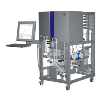
3 System description 3.2 Illustrations of ÄKTAprocess Illustrations of ÄKTAprocess Introduction This section provides illustrations of ÄKTAprocess in both the basic configuration and with all options. The main features and components are indicated. Battery limits The term 'battery limit' appears in the tables that explain the illustrations of ÄKTAprocess. Battery limit is used to indicate a delimitation point between ÄKTAprocess and the cus- tomer process equipment. - Page 45 3 System description 3.2 Illustrations of ÄKTAprocess System with standard configuration: front view The illustration below shows a front view of the standard configuration of ÄKTAprocess. ÄKTAprocess Operating Instructions 29-0252-49 AA...
- Page 46 3 System description 3.2 Illustrations of ÄKTAprocess Part Function pH probe Battery limit: System outlets (2) pH probe calibration holder EMERGENCY STOP Battery limit: Column 1 connections (2) Flow meter Battery limit: Common waste outlet Swiveling wheel with brake (4) Common waste collection cup Pre-column pressure meter Skid maneuvering handle (2)
- Page 47 3 System description 3.2 Illustrations of ÄKTAprocess System with standard configuration: rear view The illustration below shows a rear view of the standard configuration of ÄKTAprocess. ÄKTAprocess Operating Instructions 29-0252-49 AA...
- Page 48 3 System description 3.2 Illustrations of ÄKTAprocess Part Function Pneumatic air supply connection port SYSTEM POWER SWITCH EMERGENCY STOP Pressure meter Pre-column conductivity meter System pump A Moveable air sensor Battery limit: System inlets (2) Post-column conductivity meter System label ÄKTAprocess Operating Instructions 29-0252-49 AA...
- Page 49 3 System description 3.2 Illustrations of ÄKTAprocess System with all options: front view The illustration below shows a front view of an example of ÄKTAprocess with all optional components. ÄKTAprocess Operating Instructions 29-0252-49 AA...
- Page 50 3 System description 3.2 Illustrations of ÄKTAprocess Part Function Battery limit: System outlets (10) Battery limit: Column 2 connections (2) Battery limit: CIP / AxiChrom™ valves Pre-column pH probe calibration cup Pre-column pH probe Sample pump inlet In-line filter ÄKTAprocess Operating Instructions 29-0252-49 AA...
- Page 51 3 System description 3.2 Illustrations of ÄKTAprocess System with all options: rear view The illustration below shows a rear view of an example of ÄKTAprocess with all optional components. ÄKTAprocess Operating Instructions 29-0252-49 AA...
- Page 52 3 System description 3.2 Illustrations of ÄKTAprocess Part Function Pressure meter with PCV option (2) Pressure control valve Flow meter System pump B Battery limit: Buffer B inlets (6) Battery limit: Buffer A inlets (10) ÄKTAprocess Operating Instructions 29-0252-49 AA...
-
Page 53: Standard Components
3 System description 3.3 Standard components Standard components Introduction This section provides an overview of the standard components of ÄKTAprocess. In this section Section See page 3.3.1 Structural components 3.3.2 Control system components 3.3.3 Inlets and outlets 3.3.4 Meters and sensors 3.3.5 System pump 3.3.6 Air trap 3.3.7 Valves... -
Page 54: Structural Components
3 System description 3.3 Standard components 3.3.1 Structural components 3.3.1 Structural components Electric cabinet The electric cabinet serves as the container for all electrical and pneumatic equipment. Skid The rigid stainless steel structure supports all process components and the electric cabinet. -
Page 55: Control System Components
3 System description 3.3 Standard components 3.3.2 Control system components 3.3.2 Control system components Introduction This section describes the components that allow automation of ÄKTAprocess by the UNICORN control system. Control system ÄKTAprocess is fully automated by means of the UNICORN control system. Once the re- quired methods are created and approved, a non-expert user can safely operate the system. - Page 56 3 System description 3.3 Standard components 3.3.2 Control system components Communications Communication with most controlled components mounted outside the cabinet uses the PROFIBUS™ industry standard communication protocol and hardware. The PROFIBUS connection and other communication ports are located on the underside of the electrical cabinet, as shown in the illustration below.
-
Page 57: Inlets And Outlets
3 System description 3.3 Standard components 3.3.3 Inlets and outlets 3.3.3 Inlets and outlets Introduction This section describes the inlets and outlets, including the drain outlet, of ÄKTAprocess that are provided in the standard configuration. Connections The standard configuration of ÄKTAprocess has two inlets, two outlets and connections for one column. -
Page 58: Meters And Sensors
3 System description 3.3 Standard components 3.3.4 Meters and sensors 3.3.4 Meters and sensors Introduction This section describes the meters and sensors that are installed as standard components of ÄKTAprocess. Overview ÄKTAprocess is provided with a set of sensors and meters that provide data to the control system, enabling it to control the progress and detect the performance of the process in a satisfactory way. -
Page 59: System Pump
3 System description 3.3 Standard components 3.3.5 System pump 3.3.5 System pump Introduction This section describes the basic ÄKTAprocess system pump. In the standard configuration, a single system pump is provided that supports isocratic operation. Pump type The system pump is a triple head diaphragm pump, or a 5-headed diaphragm pump for flow rates 45 to 2000 l/h. -
Page 60: Air Trap
3 System description 3.3 Standard components 3.3.6 Air trap 3.3.6 Air trap Introduction An air trap is installed in the flow path of ÄKTAprocess. This section describes the air trap and the sensors that are used for liquid level control. Air trap function The function of the air trap is to de-gas buffers. -
Page 61: Valves
3 System description 3.3 Standard components 3.3.7 Valves 3.3.7 Valves General description With the exception of the filter housing options that have either one or three manual air outlet valves, all valves are diaphragm valves that are actuated by compressed air. The valve actuators are controlled by an ASi bus. -
Page 62: Filter Valves
3 System description 3.3 Standard components 3.3.7 Valves Valve default positions When the system is powered up and connected to compressed air, the default positions for the various valves are given in the table below. If no control signal is present, for ex- ample if the mains power is shut off, the valves will revert to Closed positions. - Page 63 3 System description 3.3 Standard components 3.3.7 Valves XV-023 XV-022 XV-071 Valve positions Open valve(s) Bypass XV-022 Inline (Default) XV-021 + XV-024 Fill XV-021 + XV-023 Fill_Inline XV-021 + XV-023 + XV-024 Out_through_drain XV-021 + XV-024 + XV-071 Drain (No flow) XV-023 + XV-024 + XV-071 The Drain valve position is used for example when the air trap is emptied before disas- sembly or to lower the liquid level in the air trap.
- Page 64 3 System description 3.3 Standard components 3.3.7 Valves Instruction Setting Valves:AirTrap Bypass Fill Fill_Inline Drain Out_through_drain The instruction System:Settings:Specials:AirTrapPauseFunction defines if the valve goes back to the default position (Inline) or if it remains in position when the system is set to Pause.
-
Page 65: Optional Components
3 System description 3.4 Optional components Optional components Introduction ÄKTAprocess can be ordered or upgraded with a range of optional components. This section briefly describes the optional components. Extra system pump inlets Up to eight extra inlets with individually controlled valves can be installed. This means that ÄKTAprocess is able to manage up to ten individual inlets for system pump A. - Page 66 3 System description 3.4 Optional components Two columns ÄKTAprocess can be configured to incorporate a second column. With this option, the ÄKTAprocess can supply two columns, one after the other with mobile phase. Sample pump The sample pump allows sample to be injected into the column without the need to use any of the system pumps for this purpose.
- Page 67 3 System description 3.4 Optional components Filter valves The optional in-line filter valve block set is identical to the air trap valve block set. There is also a manual valve for air evacuation, HV-301. The layout of the filter valves is illustrated in the following diagram. HV-301 XV-026 XV-072...
- Page 68 3 System description 3.4 Optional components Capsule filter and valves A disposable capsule filter option may be selected instead of the in-line filter option de- scribed above. The disposable capsule filter housing is made of polypropylene and in- cludes two additional manual valves for air evacuation, as illustrated below. Part Function Manual valve HV-301...
- Page 69 3 System description 3.4 Optional components HV-301 HV-303 FH-231 HV-302 XV-026 XV-072 Valve positions Open valve(s) Bypass (default) XV-026 Inline XV-025 + XV-027 Out_through_drain XV-025 + XV-027 + XV-072 Drain (No flow) HV-301 + HV-302 + HV-303 + XV-027 + XV-072 The Drain valve position is used, for example, when the filter housing is emptied before replacing the filter.
- Page 70 3 System description 3.4 Optional components Pressure control valves (PCV) ÄKTAprocess can be provided with up to two optional pressure control valves, PCV-341 and PCV-342, as shown in the illustration below. Note: The illustration shows PCV-341 and PCV-342 positioned horizontally. The function of the PCVs is to protect the system from 'free flow' if the inlets are fed with a higher pressure than 0.2 bar.
-
Page 71: Cip / Axichrom Manifold
See the PROFIBUS Communication Interface documenation for a description of how the different I/O-data is addressed in the mem- ory space. Contact your local GE Healthcare representative for more information. ÄKTAprocess Operating Instructions 29-0252-49 AA... -
Page 72: Flowchart
3 System description 3.5 Flowchart Flowchart AE-121 AE-131 CE/TE-102 PT-113 FT-141 AE-152 PT-112 AE-122 XV-017 XV-027 XV-025 XV-024 XV-021 PT-111 CE/TE-101 PCV-341 PCV-342 ÄKTAprocess Operating Instructions 29-0252-49 AA... - Page 73 3 System description 3.5 Flowchart Capsule filter option The illustration below shows the corresponding air trap and filter block alternative section of the flowchart if the capsule filter option is selected. XV-023 HV-301 HV-303 LEH-167 FH-231 LEL-166 HV-302 AT-221 XV-022 XV-026 XV-071 XV-072...
- Page 74 3 System description 3.5 Flowchart Function (qty) Note Column 1 bottom connection Column 2 top connection Part of column 2 option Column 2 bottom connection Part of column 2 option CIP1 to CIP4 CIP inlets CIP C CIP common inlet FH-231 Filter Option...
- Page 75 3 System description 3.5 Flowchart Function (qty) Note XV-026 Filter bypass valve Part of filter option XV-027 Filter outlet valve Part of filter option XV-028 System connection valve Part of sample pump option XV-031 Column 1 top inlet valve XV-032 Column 1 bottom inlet valve XV-033 Column 1 top valve...
- Page 76 3 System description 3.5 Flowchart Meters and sensors The following table lists the meters and sensors that are shown in the flow chart. Function Note AE-151 Buffer inlet air sensor Movable AE-152 Pre-column air sensor Final check that no air enters the column AT-121 Post-column pH-meter AT-131...
-
Page 77: Unicorn Control System
System operators are responsible for designing methods which conform to standard operating procedures and Good Manufacturing Practice procedures. UNICORN is technically compatible with all relevant sections of FDA 21 CFR Part 11. A part 11-system assessment checklist is available on request through the local GE Healthcare representative. Prerequisite knowledge At least basic knowledge of UNICORN is required to operate ÄKTAprocess safely. - Page 78 3 System description 3.6 UNICORN control system Software modules The UNICORN control software consists of four modules: Module Function Administration or Data handling and administration tasks; for example, UNICORN definition of systems and managing user profiles. Manager (UNICORN version-depen- dent) Method Editor Method creation and editing for pre-programmed con- trol of ÄKTAprocess.
- Page 79 3 System description 3.6 UNICORN control system Manual instructions Parameters can be entered manually in UNICORN for selected categories of instructions. To access the dialog where the manual instructions can be set, select the Manual menu in the System Control module, then select one of the instruction categories from the following list: •...
- Page 80 3 System description 3.6 UNICORN control system Alarms Alarm signals If equipment is connected that has lower limits than the system, the alarm levels must be set accordingly. If an analog or digital signal exceeds the predetermined alarm level, several things happen at once: •...
-
Page 81: Installation
4 Installation Installation About this chapter This chapter provides required information to enable users and service personnel to unpack, install, move and transport ÄKTAprocess. Precautions WARNING Before attempting to perform any of the procedures described in this chapter, you must read and understand all contents of the corresponding section(s) in the Safety instructions chapter, as listed below: •... -
Page 82: Site Requirements
4 Installation 4.1 Site requirements Site requirements Space and floor load For space and floor requirements, see external dimensions and weights in Section 8.1 Specifications, on page 164. Note: Make sure that the floor can handle ÄKTAprocess weight at fully loaded con- ditions. - Page 83 4 Installation 4.1 Site requirements Media supply Supply must be arranged so that piping dimensions, piping lengths, valves and height differences do not obstruct processing. Refer to Section 8.1 Specifications, on page 164 regarding media supply and delivery re- quirements. Computer An external computer is not required.
-
Page 84: Transport
4 Installation 4.2 Transport Transport Introduction This section outlines important information that must be considered when transporting ÄKTAprocess. Transport in crate Use a pallet jack or forklift with a minimum capacity to match the weight of the system plus the transport box. Refer to Section 8.1 Specifications, on page 164 regarding system weight. - Page 85 4 Installation 4.2 Transport • ÄKTAprocess can be rolled by hand on hard and level surfaces with wheel brakes released. • If the floor quality does not allow rolling ÄKTAprocess on its own wheels, it can be moved with a pallet jack or forklift. •...
-
Page 86: Unpack Äktaprocess
• the equipment for any apparent damage and document carefully, if found. If any equipment is missing or damage is found, contact your GE Healthcare representative immediately. ÄKTAprocess Operating Instructions 29-0252-49 AA... - Page 87 4 Installation 4.3 Unpack ÄKTAprocess Procedure Refer to the unpacking instructions attached to the outside of the crate when unpacking the crate. In the absence of unpacking instructions, follow the general unpacking instruc- tions below. Step Action Remove the front, side and back panels by loosening the bolts/brackets marked with black paint.
-
Page 88: Äktaprocess Setup
4 Installation 4.4 ÄKTAprocess Setup ÄKTAprocess Setup Precaution CAUTION To prevent bacterial growth, ÄKTAprocess may be partly filled with denaturated alcohol (18% C OH (ethanol), 2% C OH (iso- propanol) and 80% H O (water)) at delivery. The denatured alcohol mixture can be hazardous to humans if consumed. -
Page 89: Assembly Of Äktaprocess
4 Installation 4.4 ÄKTAprocess Setup 4.4.1 Assembly of ÄKTAprocess 4.4.1 Assembly of ÄKTAprocess Introduction Apart from the operator console, the ÄKTAprocess is delivered fully assembled. This section describes the steps needed to mount the operator console, and how to lock the wheels. - Page 90 4 Installation 4.4 ÄKTAprocess Setup 4.4.1 Assembly of ÄKTAprocess All connections to and from the monitor and the keyboard (DVI signal, USB connection and power) are included in one multi-conductor cable (ODU minisnap 24-pin connector). One ODU minisnap 3-pin connector is used for the power supply. These two cables are attached to the system, and are located underneath the electrical cabinet.
- Page 91 4 Installation 4.4 ÄKTAprocess Setup 4.4.1 Assembly of ÄKTAprocess Step Action Mount the two cables (C) to the console as illustrated in the picture. NOTICE The protective screw cap (D) should always be in place when the USB connector is not in use. Fix the cables neatly together with the existing cables underneath the cabinet using cable ties, as illustrated below.
- Page 92 4 Installation 4.4 ÄKTAprocess Setup 4.4.1 Assembly of ÄKTAprocess Step Action Fix the rotation stop onto the cabinet, behind the console arm. The bolts holding it in place should be positioned below the plane of the rotation stop plate. The position of the rotation stop is shown below viewed from the front and back.
- Page 93 4 Installation 4.4 ÄKTAprocess Setup 4.4.1 Assembly of ÄKTAprocess • The rotation stop is fixed to the cabinet with the bolts holding it in place above the plane of the rotation stop plate, as illustrated below. NOTICE Operator console • Do not use the operator console to push or drag the system •...
-
Page 94: Setup Of Control System And Network
4 Installation 4.4 ÄKTAprocess Setup 4.4.2 Setup of control system and network 4.4.2 Setup of control system and network Control system ÄKTAprocess is delivered with the UNICORN control system pre-installed and configured on the built-in computer. No specific actions are required with respect to the control system. - Page 95 4 Installation 4.4 ÄKTAprocess Setup 4.4.2 Setup of control system and network Step Action Connect the crossover Ethernet cable from CU-960 to the network socket at the bottom of the cabinet by moving the cable connector from the internal computer’s LAN2 outlet to the network socket. WARNING If the system is operated from a remote controlling computer, the operator must always make sure that no one is present and ex-...
- Page 96 Customer I/O connections are located on the communications panel on the underside of the electrical cabinet. There are many different applications for the Customer I/O connections. Refer to the product documentation package or contact your local GE Healthcare representative for more detailed technical information.
- Page 97 4 Installation 4.4 ÄKTAprocess Setup 4.4.2 Setup of control system and network Signal Digital In 1 Digital In 2 Digital In 3 Digital In 4 Digital In Common Digital Out 1 Digital Out 2 Digital Out 3 Digital Out 4 Digital Out Common Remote alarm output Remote alarm output...
-
Page 98: Connect Compressed Air Supply
4 Installation 4.4 ÄKTAprocess Setup 4.4.3 Connect compressed air supply 4.4.3 Connect compressed air supply Introduction This section describes how to connect the compressed air supply. For requirements on air supply, refer to Section 4.1 Site requirements, on page 82 and General technical data, on page 164. -
Page 99: Guidelines For Connections
4 Installation 4.4 ÄKTAprocess Setup 4.4.4 Guidelines for connections 4.4.4 Guidelines for connections Introduction This section provides guidelines for the connection of process components to ÄKTAprocess. Process connections • Use piping or tubing that has an internal diameter sufficient for the flow rate specified. The inner diameter of the tubing and its connections should be greater than or equal to the corresponding diameter of the system. -
Page 100: Connect Sample Pump
4 Installation 4.4 ÄKTAprocess Setup 4.4.5 Connect sample pump 4.4.5 Connect sample pump Overview If ÄKTAprocess is delivered with the sample pump option, connect the sample pump with the enclosed tubing using TC-connectors. Refer to the Section 3.5 Flowchart, on page 72 for sample pump connection location. - Page 101 4 Installation 4.4 ÄKTAprocess Setup 4.4.5 Connect sample pump Connections Follow the instruction below to connect the sample pump to ÄKTAprocess. Step Action Connect the sample pump air supply hose (marked P2) to the T-connector (marked P1) on the system air supply hose. Connect the sample pump ASi cable (marked E2) to the system ASi cable T- connector (marked E1).
-
Page 102: Connect A Column
4 Installation 4.4 ÄKTAprocess Setup 4.4.6 Connect a column 4.4.6 Connect a column Introduction This section outlines the steps needed to connect a column to ÄKTAprocess. Important NOTICE Make sure that the connections to the column and system comply with the requirements in the column and system Operating Instruc- tions. - Page 103 4 Installation 4.4 ÄKTAprocess Setup 4.4.6 Connect a column Connect an empty column Follow the instruction below to connect an empty column to ÄKTAprocess. Step Action Connect tubing between the system valve marked COLUMN BOTTOM and the column bottom. Connect tubing between the system valve marked COLUMN TOP and the column top.
- Page 104 4 Installation 4.4 ÄKTAprocess Setup 4.4.6 Connect a column Connect a packed column with bypass lines/valves Follow the instruction below to connect a pre-packed column with bypass lines/valves to ÄKTAprocess. Step Action Connect tubing between the column bottom and the system valve marked COLUMN BOTTOM.
-
Page 105: Power Supply
4 Installation 4.5 Power supply Power supply Introduction This section gives an overview of the power requirements for ÄKTAprocess. This includes a description of the various circuit breakers. Power requirements The power supply requirements are specified in Section 8.1 Specifications, on page 164. WARNING Protective ground. - Page 106 4 Installation 4.5 Power supply UPS power supply GE Healthcare does not offer a UPS (Uninterrupted Power Supply) as an accessory. However, the system is prepared for UPS operation. CAUTION Do not use an Uninterruptible Power Supply (UPS) outside the range 100 to 240 V.
- Page 107 4 Installation 4.5 Power supply Power supply cable The mains power supply cable is shielded ÖLFLEX™ of type: • CE-classified: 150CY Quattro (3 x 2.5 mm • UL-classified: CRF (3 x 14AWG) If the cable needs to be replaced due to damage, the same type of cable or equivalent must be used.
- Page 108 Equal to or larger than the L and N-wire Ground fault breaker ÄKTAprocess is not equipped with a general Ground Fault Circuit Breaker and it is not an option that is available from GE Healthcare. However, if ground fault protection for the system is required: •...
- Page 109 4 Installation 4.5 Power supply UL standard systems UL standard systems are equipped with additional circuit breakers, CB5, CB6 and CB7, protecting the DC power supply to the built-in computer, LCD monitor and instruments in the electric cabinet. More information Wiring diagrams for the system, voltage, power, fuse requirements and the tripping current for the fixed power supply ground fault protector can be found in the system documentation package.
-
Page 110: Operation
5 Operation Operation About this chapter This chapter provides the information required to safely operate ÄKTAprocess. In this chapter This chapter contains the following sections: Section See page 5.1 Prepare the system 5.2 Perform a run 5.3 Shut down the system and software ÄKTAprocess Operating Instructions 29-0252-49 AA... - Page 111 5 Operation Precautions WARNING Before attempting to perform any of the procedures described in this chapter, you must read and understand all contents of the corresponding section(s) in the Safety instructions chapter, as listed below: • General precautions, on page 17 •...
-
Page 112: Prepare The System
5 Operation 5.1 Prepare the system Prepare the system Introduction This section describes the steps that should be performed to prepare ÄKTAprocess for a run. Prerequisites Before ÄKTAprocess is taken into operation, make sure that all procedures in the relevant chapters and sections have been performed, including: •... -
Page 113: Start The System And Software
5 Operation 5.1 Prepare the system 5.1.1 Start the system and software 5.1.1 Start the system and software Start ÄKTAprocess CAUTION When handling the operator console, make sure that no body parts are caught between the sections of the console arm. Step Action Make sure that the air supply to the system is turned on. - Page 114 5 Operation 5.1 Prepare the system 5.1.1 Start the system and software Start UNICORN Refer to Section 3.6 UNICORN control system, on page 77 for more information regarding the UNICORN control system, warnings and alarms. Step Action If your system setup requires you to log into the operating system, log in to the Microsoft Windows operating system and start UNICORN by double- clicking the icon on the desktop.
-
Page 115: Prepare System Components
5 Operation 5.1 Prepare the system 5.1.2 Prepare system components 5.1.2 Prepare system components Introduction This section outlines the steps needed to prepare the pH meter, UV monitor and air sensors before a run. pH calibration The pH meter is removed from the flow path for calibration. Calibrate the pH meter ac- cording to Section 6.5 Calibration of pH probe, on page 148. - Page 116 5 Operation 5.1 Prepare the system 5.1.2 Prepare system components Step Action Insert the assembled pH electrode into the pH flow cell and fasten the nut. Make sure that the electrode is tightened correctly to prevent leakage. Connect the monitor cable to the electrode. Connect the reference electrode to the grounding wire connected to the pH cell.
- Page 117 5 Operation 5.1 Prepare the system 5.1.2 Prepare system components Air sensors The movable air sensor may be optionally mounted on any inlet. When not in use, it should be placed in the recessed holder on the inlet side of the system frame as illustrated below.
-
Page 118: Priming And Leakage Test
5 Operation 5.1 Prepare the system 5.1.3 Priming and leakage test 5.1.3 Priming and leakage test Introduction Before a run is started the system should be primed and tested for possible leakage. This section describes a procedure for priming and testing for leakage. Important NOTICE All system parts must be correctly filled with liquid before any... - Page 119 5 Operation 5.1 Prepare the system 5.1.3 Priming and leakage test Step Action When the tubing from the buffer tanks is connected to the corresponding inlets, carefully open the clamp at the system inlet valve connection to prime/fill the tubing as much as possible. When the liquid has reached the connection, tighten the clamp again.
- Page 120 5 Operation 5.1 Prepare the system 5.1.3 Priming and leakage test Step Action Check that the flow meter signal is stable and has a reasonable reading. Increase the flow rate stepwise to maximum system capacity. Check for leaks and inspect that pressure sensors and the other instrument readings (e.g., pH/conductivity) are at an acceptable level.
-
Page 121: Set Pressure Control Valve Parameters
5 Operation 5.1 Prepare the system 5.1.4 Set pressure control valve parameters 5.1.4 Set pressure control valve parameters Introduction After the priming and leakage test, and before a run is started, the pressure control valve (PCV) or valves on the system need to be adjusted. The purpose of this adjustment is to achieve correct flow through the system as a result of the feed pressure on the inlets. - Page 122 5 Operation 5.1 Prepare the system 5.1.4 Set pressure control valve parameters Set other valve parameters To set the parameters Hold backpressure and Boost in the PCV instruction settings, follow the steps described below: Step Action Set Hold backpressure to 0.5 bar over the buffer pressure. Note: The valve adjusts the pressure to the Inlet A Hold back tank pressure param- eter, so it must not be set lower than the buffer pressure.
-
Page 123: Final Checks
5 Operation 5.1 Prepare the system 5.1.5 Final checks 5.1.5 Final checks Checklist Make sure that the actions listed below are completed before the system is started. • Check the condition of all connections and gaskets. • Check that no chemicals that may be harmful to the system will be used. •... -
Page 124: Perform A Run
5 Operation 5.2 Perform a run Perform a run Precautions WARNING Cabinet doors. During operation, all doors must always be closed and locked. WARNING Use a harmless fluid in the beginning of the process. This will make it possible to detect leakage with minimized consequences and the risk for potential leakage of hazardous fluids is avoided. - Page 125 5 Operation 5.2 Perform a run Start a run Follow the instruction below to start a run. Step Action In the System Control module, select Run in the File menu. Select the method to start. Click OK. A Start Protocol is displayed, consisting of a number of dialog boxes. On the Variables page, it is possible to fine-tune the method before proceeding.
- Page 126 5 Operation 5.2 Perform a run End the run Normal completion If no unexpected events occur during the run, UNICORN enters END state at method completion without need for user interaction. End before method has finished If the method needs to be terminated before it has run to completion, follow the instruc- tion below.
-
Page 127: Shut Down The System And Software
5 Operation 5.3 Shut down the system and software Shut down the system and software Introduction This section describes the steps that should be taken when shutting down ÄKTAprocess and the UNICORN control software. WARNING Shutdown does not automatically result in depressurizing of the piping system. -
Page 128: Maintenance
6 Maintenance Maintenance About this chapter This chapter provides information to enable users and service personnel to clean, maintain, calibrate and store ÄKTAprocess. In this chapter This chapter contains the following sections: Section See page 6.1 User maintenance schedule 6.2 Cleaning 6.3 Storage 6.4 Disassembly and assembly 6.5 Calibration of pH probe... - Page 129 6 Maintenance WARNING For continued protection against injury risks due to fluid jets, burst pipes or potentially explosive atmosphere, the piping system must be tested for leakage at maximum pressure: • After assembly or maintenance • Before operation or CIP CAUTION Decontaminate before service.
-
Page 130: User Maintenance Schedule
6 Maintenance 6.1 User maintenance schedule User maintenance schedule Introduction The maintenance recommendations are different depending on how frequently you use your system. Note that the recommendation may not apply to your specific use of the system. The system owner is solely responsible for establishing applicable routines for periodic maintenance. - Page 131 It is recommended that after a power down a calibration of the level sensors should always be performed. Pump Check for oil leakage. (If the pump leaks, contact your local GE Healthcare representative). Connections and Check for leakage. Replace seals if needed. Perform a leakage seals test at maximum operating pressure.
-
Page 132: Flow Meter
It is recommended that the adjustment is per- formed by a GE Healthcare service engineer. Prior to the adjustment it is very important to fill the system completely with liquid so that no air is trapped in the flow meter. - Page 133 If a “Valve error" has been triggered, a valve calibration may restore the valve function. If a valve calibration does not help, contact your local GE Healthcare representative. To perform a valve calibration, use the instruction Valves:Calibrate_Valves:XVxxx (select the valve that is to be calibrated).
-
Page 134: Cleaning
6 Maintenance 6.2 Cleaning Cleaning Introduction This section describes procedures and recommendations for cleaning ÄKTAprocess. Procedures for cleaning both the exterior, and CIP (cleaning-in-place) protocols for cleaning the flow path are described. Precautions WARNING Flammable liquids. ÄKTAprocess is not approved to handle flammable liquids. - Page 135 6 Maintenance 6.2 Cleaning NOTICE The filter (optional) may not be compatible with the CIP solutions. If so, remove the filter and store or dispose of it in accordance with the recommendations of the manufacturer. In this section This section contains the following subsections: Section See page 6.2.1 Important considerations for cleaning...
-
Page 136: Important Considerations For Cleaning
6 Maintenance 6.2 Cleaning 6.2.1 Important considerations for cleaning 6.2.1 Important considerations for cleaning Cleaning frequency A suitable frequency of routine cleaning is determined by the nature of the starting material and the type of process. However, routine cleaning shall be performed at intervals aimed at prevention rather than cleaning the system from growth or contami- nation. - Page 137 6 Maintenance 6.2 Cleaning 6.2.1 Important considerations for cleaning Clean external surfaces ÄKTAprocess is designed to be operated in a clean environment and the external surfaces should not normally accumulate any substantial amount of dust or dirt. Regularly, wipe the outside of ÄKTAprocess with a clean cloth. Use a mild cleaning agent such as water, followed by 70% ethanol.
-
Page 138: Cleaning-In-Place (Cip)
6 Maintenance 6.2 Cleaning 6.2.2 Cleaning-in-place (CIP) 6.2.2 Cleaning-in-place (CIP) Introduction This section provides general information about the CIP procedure, and provides some general guidelines for CIP procedures. For a detailed instruction, refer to Section 6.2.3 General procedure for CIP and sanitization, on page 141. CIP hook-up During the CIP procedure, the column can be replaced with a bypass manifold or spool piece. - Page 139 6 Maintenance 6.2 Cleaning 6.2.2 Cleaning-in-place (CIP) Using the CIP/AxiChrom manifold option This flow scheme shows an example of how to use the CIP/AxiChrom manifold option for CIP on a system configured with the B-pump option. XV-003, 005, 007, 009 FT-142 XV-001 PT-115...
- Page 140 Function CIP distribution manifold, provided by customer. CIP connection hoses, provided by customer. CIP-manifold, provided by GE Healthcare. Specific manifolds are available as optional equipment for each system battery limit. For a detailed description of the process components, see Section 3.5 Flowchart, on page 72.
-
Page 141: General Procedure For Cip And Sanitization
6 Maintenance 6.2 Cleaning 6.2.3 General procedure for CIP and sanitization 6.2.3 General procedure for CIP and sanitization Introduction The system can be cleaned using 1 M sodium hydroxide as outlined in the procedure below. Note: The system owner must qualify a cleaning and sanitizing procedure that is suitable for the required application. - Page 142 6 Maintenance 6.2 Cleaning 6.2.3 General procedure for CIP and sanitization Inlets If the system has optional CIP valves and CIP manifolds: • Connect tubing between the CIP valves and tanks filled with suitable solutions for system CIP. For example 1 M sodium hydroxide in CIP 1, water in CIP 2 and 20% ethanol in CIP3.
- Page 143 6 Maintenance 6.2 Cleaning 6.2.3 General procedure for CIP and sanitization Step Action When the filling sequence is completed, let the system stand for 60 minutes. See Section Section 8.5 UNICORN method for system CIP/Sanitization/Rinsing, on page 172 for an example of a UNICORN method for a two-pump, 10 mm inner diameter system. After cleaning •...
-
Page 144: Storage
If the system is dried, the valve bodies should be grounded before nitrogen or air flow is applied. Contact your GE Healthcare repre- sentative regarding purchase and installation of grounding kits. NOTICE Fit protective caps on all electrical and optical connectors when not in use. - Page 145 6 Maintenance 6.3 Storage Step Action Replace the pH electrode with the pH CIP cap (pH plug). The electrode should be stored in 3 M potassium chloride. Place the pH electrode in the pH elec- trode holder, with the end submerged in storage solution. Note: Do not store the pH electrode in water only.
-
Page 146: Disassembly And Assembly
This section covers all disassembly and assembly procedures that the end user is allowed to perform without support from GE Healthcare. Precautions WARNING Only personnel authorized by GE Healthcare may open the cabinet doors. There is high voltage inside the cabinet that can cause human injury or death. WARNING The electric cabinet doors may only be opened when ÄKTAprocess... - Page 147 Other than described in this chapter, ÄKTAprocess is not designed to be disassembled or assembled by the user. If the need for further disassembly should arise, always contact your GE Healthcare representative for advice before attempting any actions not described in this document.
-
Page 148: Calibration Of Ph Probe
6 Maintenance 6.5 Calibration of pH probe Calibration of pH probe Required equipment The following solutions and equipment are required for calibration of the pH probe: • pH reference solution for low pH-measuring point, preferably pH 4.00 • pH reference solution for high pH-measuring point, preferably pH 7.00 •... - Page 149 6 Maintenance 6.5 Calibration of pH probe Images of pH probe The left image below shows the pH probe located for storage and calibration. A cup has been placed in the cup holder. The right image below shows the pH flow cell for operation. Off-line pH calibration The table below describes how to calibrate the pH probe.
- Page 150 6 Maintenance 6.5 Calibration of pH probe Step Action Remove the cup with the first buffer from the holder and replace it with the cup with the second buffer. Re-insert the pH probe into the holder, with the end submerged in the buffer. Enter the pH value for the second buffer (with the lowest pH solution) in the Reference value 2 field, wait for the value to stabilize, and press Read value Wait for response and, if the electrode passed, press Close.
-
Page 151: Repair And Calibration
This section describes component checks, repair and calibration of components other than the pH probe that the user can perform without GE Healthcare support. Calibration of the pH probe is described in Section 6.5 Calibration of pH probe, on page 148. -
Page 152: Pump Calibration
6 Maintenance 6.6 Repair and calibration 6.6.1 Pump calibration 6.6.1 Pump calibration Introduction Pumps are multiple head diaphragm pumps. Each pump is provided with adjustment knobs controlling the stroke length of the pump head cylinders. Check the stroke length The stroke length is factory set to maximum for optimum performance according to the system specifications and should never be changed by the user. -
Page 153: Air Trap Calibration
6 Maintenance 6.6 Repair and calibration 6.6.2 Air trap calibration 6.6.2 Air trap calibration Introduction The air trap contains sensors that control the liquid level within the air trap, see Sec- tion 3.3.6 Air trap, on page 60. This section includes a function test for the air level sensors, and two procedures for calibration of the sensors, both automatic and manual. - Page 154 6 Maintenance 6.6 Repair and calibration 6.6.2 Air trap calibration Automatic calibration of level sensors Follow the instruction below to calibrate the air trap sensors automatically. Step Action Empty the air trap completely from liquid using the Drain instruction for the air trap (see Air trap valves, on page 62).
- Page 155 6 Maintenance 6.6 Repair and calibration 6.6.2 Air trap calibration Step Action Hold the iron tool close to the cross hairs on the side of the level sensor for a few seconds (> 5 sec but < 10 sec), until the green indicator light starts flashing at a higher rate than above (approximately 2 Hz).
-
Page 156: Component Replacement
6 Maintenance 6.6 Repair and calibration 6.6.3 Component replacement 6.6.3 Component replacement Replacement of filter Many optional filters may be used with ÄKTAprocess. Please refer to the filter documen- tation for instructions on how to replace the filter. Replacement of batteries The built-in computer is equipped with a long-life Lithium battery for BIOS functions. -
Page 157: Troubleshooting
This chapter provides information to assist users and service personnel to identify and correct problems that may occur when operating ÄKTAprocess. If the suggested actions in this guide do not solve the problem, or if the problem is not covered by this guide, contact your GE Healthcare representative for advice. Precautions WARNING... - Page 158 Maintenance annually or as needed, on page 131. If a valve calibration does not help, contact your local GE Healthcare representative. If the “Valve error” alarm is accompanied by “No air supply to the system”, the alarm is caused by a com- pressed air failure (see above).
- Page 159 No inlet or outlet valve open. Check method and • valves. Incorrect method. Check by entering • Pump:ManFlow > 1%. If none of the above, contact GE Healthcare service • personnel. Little or no flow Check that the connected inlet is actually used. •...
- Page 160 Refer to the pump manual in the product documenta- tion package for replacement instructions. However, it is recommended that you contact your service repre- sentative from GE Healthcare for pump maintenance. Note: The alarm for the pump diaphragms (Pump_Alarm) may be enabled or disabled in UNICORN.
- Page 161 7 Troubleshooting Error symptom Possible cause Corrective action Noisy UV-signal, signal drift Bad UV fiber connections Check the connections of the UV cell or instability optical fiber (replace if necessary) Dirty UV cell Clean the UV cell as described in Clean the UV and conductivity cell, on page 136 Pressure curve...
- Page 162 7 Troubleshooting Conductivity The table below describes error symptoms that may occur with conductivity measure- ments, together with possible corrective actions. Error symptom Possible cause Corrective action Baseline drift or noisy signal Leaking tube connections Tighten the clamps. If necessary, re- place the clamps.
-
Page 163: Reference Information
8 Reference information Reference information About this chapter This chapter provides reference information that may become useful when installing, operating, maintaining and troubleshooting ÄKTAprocess. Further information to assist in ordering parts and accessories is also provided. The ÄKTAprocess is a modular built instrument that can be configured in many different ways. -
Page 164: Specifications
8 Reference information 8.1 Specifications Specifications Introduction This section contains technical data pertaining to the ÄKTAprocess and its components. For complete technical data, refer to the GS in the product documentation package. General technical data The following table provides general technical data for the complete system. Property Value Process operating... -
Page 165: Cabinet
8 Reference information 8.1 Specifications Cabinet type specific data The following table provides technical data pertaining to the cabinet type. Property Cabinet 10 Cabinet 30 Voltage rating 100, 120, 200 to 208, 230 or 200 to 208, 230 or 240V / 50- 240V / 50-60 Hz 60 Hz Max power... - Page 166 8 Reference information 8.1 Specifications Temperature and pressure limits The table below gives temperature and pressure limits for various types of tubing. Tubing material Tubing diameter Fluid temperature Maximum pres- sure Polypropylene 4ºC to 40ºC 6 bar* 40ºC to 60ºC 3 bar Stainless steel 3/8", 1/2"...
-
Page 167: Chemical Resistance
Chemical resistance Introduction The table below gives allowed exposure concentrations and times for various chemicals that may be used in GE Healthcare BioProcess instruments in general. Some of the chemicals listed may not be applicable for your instrument. WARNING Flammable liquids. ÄKTAprocess is not approved to handle flammable liquids. - Page 168 8 Reference information 8.2 Chemical resistance Chemical Concentration Max time / cycle Max acc. expos. Usage Phosphoric acid Overnight Unlimited For stainless steel passiva- tion 2-propanol 1000 h Sodium chloride 0 to 3 M 3000 h Purification, CIP Sodium 1 M at pH=14 24 h at temp ≤40°C 1000 days hydroxide...
-
Page 169: Gradient Performance
8 Reference information 8.3 Gradient performance Gradient performance Introduction This section contains information on how the system can be configured to develop gradients using feedback loop technology. Gradient performance ÄKTAprocess can be configured to develop gradients at any flow rate using feedback loop technology with an accuracy better than ±... - Page 170 8 Reference information 8.3 Gradient performance UNICORN instruction notes Pump:Flow: 0.0 to XX l/h. The pump is regulated by feedback from the flow meter. XX is for example 180 l/h for a 6 mm inner diameter system. Pump:ManFlow: 0.0 to 100% of the maximum pump capacity. Sets the pump speed to a fixed value.
-
Page 171: Decontamination Report
Decontamination Report ______________________________________________________________________ 1. Equipment that is returned, for service or any other reason when personnel connected to GE Healthcare must handle the equipment (at any location), should be cleaned. 2. This form must be used to log the decontamination of the equipment. -
Page 172: Unicorn Method For System Cip/Sanitization/Rinsing
8 Reference information 8.5 UNICORN method for system CIP/Sanitization/Rinsing UNICORN method for system CIP/Sanitization/Rinsing Introduction This section provides an example of a complete method that may be used for system cleaning. Main method The method outlined here is an example designed for a 2-pump, 10 mm inner diameter system (max flow 600 l/h). - Page 173 8 Reference information 8.5 UNICORN method for system CIP/Sanitization/Rinsing 1.00 InletA InletA3 1.50 InletA InletA4 2.00 InletA InletA5 2.50 InletA InletA6 3.00 InletA InletA7 3.50 InletA InletA8 4.00 InletA InletA9 4.50 InletA InletA10 5.00 InletA InletA1 5.00 End_Block 0.00 Block Fill_all_B_inlets (Fill_all_B_inlets) 0.00 Base SameAsMain 0.00 Gradient 100 {%B} 0.00 {base}...
- Page 174 8 Reference information 8.5 UNICORN method for system CIP/Sanitization/Rinsing 0.00 Base SameAsMain 0.00 Filter Bypass 0.50 Filter Out_through_drain 1.00 Filter Inline 1.00 Message "Open manual filter valve" Screen "No sound" 1.00 Pause INFINITE {Minutes} 2.00 Message "Close manual filter valve" Screen "No sound" 2.00 Pause INFINITE {Minutes} 2.00 End_Block 0.00 Block Fill_all_column_valves...
-
Page 175: Further Information
Specification in the product documentation package. Spare parts and accessories Additional information regarding spare parts and accessories can be found in the product documentation package. Your local GE Healthcare representative will also be able to suggest recommended spare parts and accessories. Remaining aspects Regarding •... -
Page 176: Index
Index Index Documentation Software, UNICORN, 15 Accessories, 175 Drain outlet, 57 Air trap Drains, 57 Valves, 62 ÄKTAprocess Flow chart, 76 Electrical power, 82 Illustration, 44 Electric cabinet, 54 Intended use, 7 Emergency Ambient environment, 82 Procedures, 34 Restarting the system, 37 Shutdown, 35 Cabinet, 43 Stop, 35... - Page 177 Index Manufacturing information, 10 Sample pump, 24, 66 Media supply, 83 Service , 175 Meters and sensors, 58 Skid, 54 Method optimization, 175 Space and floor load, 82 More information, 175 Spare parts, 175 Storage, long term, 145 Storage, short term, 144 System Notes and tips, 9 Description, 42...
- Page 178 Index Error, 133, 158 LED indicator lights, 61 Wetted materials, 175 Valves general description, 61 ÄKTAprocess Operating Instructions 29-0252-49 AA...
- Page 180 All goods and services are sold subject to the terms and conditions of sale of the company within GE Healthcare which supplies them. A copy of these terms and conditions is available on request. Contact your local GE Healthcare repre- sentative for the most current information.
Need help?
Do you have a question about the AKTAprocess and is the answer not in the manual?
Questions and answers