Table of Contents
Advertisement
Quick Links
Advertisement
Chapters
Table of Contents
Troubleshooting

Subscribe to Our Youtube Channel
Related Manuals for GE AKTA ready


Summary of Contents for GE AKTA ready
- Page 1 ÄKTA ™ ready Operating Instructions Original instructions...
-
Page 2: Table Of Contents
Table of Contents Table of Contents Introduction ......................Important user information ......................Regulatory information ........................Associated documentation ......................Safety instructions ....................Safety precautions ..........................Labels ................................. Emergency procedures ........................Recycling information ......................... Declaration of Hazardous Substances (DoHS) ................ System description ....................Overview .............................. - Page 3 Table of Contents The test report ............................Troubleshooting a failed component test ................. Column installation ..................... Columns ..............................Installing a column ..........................Optional column test ........................... Optional column rinsing ........................Adding columns to the column list ....................10 Creating a method ....................10.1 The Method Editor ..........................
- Page 4 Table of Contents 14.5 PID control ..............................14.6 Checklists ..............................14.7 Health and Safety Declaration Form ................... 14.8 More information ..........................Index ........................ÄKTA ready Operating Instructions 28960345 AD...
-
Page 5: Introduction
1 Introduction Introduction Purpose of the Operating Instructions The Operating Instructions provides you with the instructions needed to handle ÄKTA ready in a safe way. It also describes the procedures required to operate ÄKTA ready on a day-to-day basis, as well as technical information and instructions for troubleshooting and maintenance. Prerequisites In order to operate the system in the way it is intended, the following pre-requisites must be fulfilled:... - Page 6 1 Introduction In this chapter This chapter contains the following sections: Section See page 1.1 Important user information 1.2 Regulatory information 1.3 Associated documentation ÄKTA ready Operating Instructions 28960345 AD...
-
Page 7: Important User Information
1 Introduction 1.1 Important user information Important user information Read this before using ÄKTA ready All users must read the safety instructions in the ÄKTA ready user documentation to fully understand the safe use of ÄKTA ready, before installing, using, or maintaining the system. - Page 8 1 Introduction 1.1 Important user information Notices NOTICE NOTICE indicates instructions that must be followed to avoid damage to the product or other equipment. Notes and tips Note: A note is used to indicate information that is important for trouble-free and optimal use of the product.
-
Page 9: Regulatory Information
EU Declaration of Conformity (DoC) document. Requirement Content Name and address of manufacturer GE Healthcare Bio-Sciences AB, Björkgatan 30, SE 751 84 Uppsala, Sweden Conformity with EU Directives This product complies with the European directives listed in the table, by fulfilling the corresponding harmonized standards. - Page 10 • connected to other products recommended or described in the user documentation, • used in the same state as it was delivered from GE Healthcare, except for alterations described in the user documentation. International standards Harmonized standard requirements fulfilled by this product are summarized in the fol-...
- Page 11 The user is cautioned that any changes or modifications not expressly approved by GE Healthcare could void the user’s authority to operate the equipment. This equipment has been tested and found to comply with the limits for a Class A digital device, pursuant to part 15 of the FCC Rules.
-
Page 12: Associated Documentation
1 Introduction 1.3 Associated documentation Associated documentation Generic documentation Together with each system, the following manuals are supplied providing information that applies to ÄKTA ready independent of the specific configuration. Document Purpose/Contents ÄKTA ready Operating Instructions on how to handle ÄKTA ready in a safe Instructions way (this manual). - Page 13 1 Introduction 1.3 Associated documentation Related literature Document Product Product code ReadyToProcess™ columns User Manual User Manual 28925644 ReadyToProcess columns Data file 28915987 ÄKTA ready chromatography system Data file, including Site 28915986 Preparation Guide Keep your ÄKTA ready operating in peak Preventive Maintenance 28998083 condition...
-
Page 14: Safety Instructions
2 Safety instructions Safety instructions About this chapter This chapter describes safety precautions and emergency shutdown procedures for the product. The labels on the system and information regarding recycling are also described. Important WARNING Before installing, operating or maintaining the product, all users must read and understand the entire contents of this chapter to become aware of the hazards involved. -
Page 15: Safety Precautions
2 Safety instructions 2.1 Safety precautions Safety precautions Introduction ÄKTA ready is powered by mains voltage and handles materials that may be hazardous. Before installing, operating or maintaining the system, you must be aware of the hazards described in this manual. The safety precautions in this section are grouped into the following categories: •... -
Page 16: Personal Protection
Emergency stop. Pressing the EMERGENCY STOP does not automatically depressurize the flow path. • Do not use any accessories not supplied or recommended by GE Healthcare. CAUTION • Waste tubes and containers must be secured and sealed to prevent accidental spillage. -
Page 17: Flammable Liquids And Explosive Environment
2 Safety instructions 2.1 Safety precautions WARNING • Personal Protective Equipment (PPE). Whenever packing, unpacking, transporting or moving the product, wear: Protective footwear, preferably with steel toe-cap. Working gloves, protecting against sharp edges. Protective glasses. Flammable liquids and explosive environment WARNING •... - Page 18 2 Safety instructions 2.1 Safety precautions WARNING • Access to power switch and power cord with plug. Do not block access to the power switch and power cord. The power switch must always be easy to access. The power cord with plug must always be easy to disconnect.
-
Page 19: Operation
Do not turn on the Mains power switch before all connections are made. • ÄKTA ready shall be installed and prepared by personnel from GE Healthcare or third party authorized by GE Healthcare. Contact GE Healthcare if you require re-installation at a new site. Operation WARNING •... - Page 20 • Use columns that withstand expected pressures. If not, the columns might rupture, resulting in injury. Preferably use ReadyToProcess columns from GE Healthcare. • Over-pressure. Never block the outlet tubing with, for instance, stop plugs, since this will create over-pressure and might result in injury.
- Page 21 Do not use chemicals at temperatures above the specified limits. NOTICE • Only use flow kits, supplied by GE Healthcare. • Excessive temperatures may damage the equipment. Do not run the system at higher temperatures than the specified maximum operation temperature as stated on the system la- bel.
- Page 22 Operating Instructions. • Use only GE parts. Only spare parts and accessories that are approved or supplied by GE Healthcare may be used for maintaining or servicing the product.
- Page 23 2 Safety instructions 2.1 Safety precautions NOTICE • Only use 0.5 M NaOH in the flow kit for a maximum time of 2 hours. Flush the flow kit tubing with a suitable rinsing liquid to remove the NaOH. • Disconnect power. To prevent equipment damage, always disconnect the power from the product before an instrument module is removed or installed, or a cable is connected or disconnected.
-
Page 24: Labels
2 Safety instructions 2.2 Labels Labels Introduction This section describes the various labels on ÄKTA ready and their meaning. System label The system label is located on the right side of the leg support of the ÄKTA ready cabinet. Note: The specific data shown on this system label is only an example. - Page 25 2 Safety instructions 2.2 Labels Label text Description Code Number Identifies the system as being an ÄKTA ready. System Number Identifies the (unique) system installation. Manufacturing Year Manufacturing year Supply Voltage The voltage alternatives for ÄKTA ready. Configured For The voltage the system is currently configured for. Frequency Supply voltage frequency Max Power Consumption...
- Page 26 2 Safety instructions 2.2 Labels Label text Description This symbol indicates that ÄKTA ready has been certi- fied by a Nationally Recognized Testing Laboratory (NRTL). NRTL means an organization, which is recog- nized by the US Occupational Safety and Health Ad- ministration (OSHA) as meeting the legal requirements of Title 29 of the Code of Federal Regulations (29 CFR), Part 1910.7.
-
Page 27: Emergency Procedures
2 Safety instructions 2.3 Emergency procedures Emergency procedures In this section This section describes how to do an emergency shutdown of ÄKTA ready and the result in the event of power failure. Precautions WARNING • Emergency stop. Pressing the EMERGENCY STOP will not shut off mains power to the cabinet. - Page 28 2 Safety instructions 2.3 Emergency procedures Emergency shutdown In a situation where there is a risk of injury, switch off the ongoing run by pressing the EMERGENCY STOP on the front of the system cabinet. If required, also switch off the mains power supply.
- Page 29 A UPS (Uninterrupted Power Supply) protects against temporary power failures by en- abling the system to continue to operate for a limited time. A UPS is not included with the system. Contact your local GE Healthcare representative for more information about the options for your specific system.
-
Page 30: Recycling Information
Recycling of hazardous substances The product contains hazardous substances. Detailed information is available from your GE Healthcare representative. Disposal of electrical components Waste electrical and electronic equipment must not be disposed as unsorted municipal waste and must be collected separately. -
Page 31: Declaration Of Hazardous Substances (Dohs)
2 Safety instructions 2.5 Declaration of Hazardous Substances (DoHS) Declaration of Hazardous Substances (DoHS) 根据 SJ/T11364-2014《电子电气产品有害物质限制使用标识要求》特提供如下有关污染控制方面 的信息。 The following product pollution control information is provided according to SJ/T11364-2014 Marking for Restriction of Hazardous Substances caused by electrical and electronic products. 电子信息产品污染控制标志说明... - Page 32 2 Safety instructions 2.5 Declaration of Hazardous Substances (DoHS) 有害物质的名称及含量 Name and Concentration of Hazardous Substances 产品中有害物质的名称及含量 Table of Hazardous Substances’ Name and Concentration List of hazardous substances Component name Hazardous substance 部件名称 有毒有害物质或元素 Cr6+ PBDE 铅 汞 镉 六价铬 多溴联苯...
-
Page 33: System Description
3 System description System description About this chapter This chapter provides an overview of the technical properties of ÄKTA ready. In this chapter This chapter contains the following sections: Section See page 3.1 Overview 3.2 Layout 3.3 Flow chart 3.4 Equipment 3.5 UNICORN control system ÄKTA ready Operating Instructions 28960345 AD... -
Page 34: Overview
3 System description 3.1 Overview Overview Intended use of ÄKTA ready ÄKTA ready is an isocratic, low pressure, automated liquid chromatography system using ÄKTA ready flow kits (ÄKTA ready Low Flow Kit or ÄKTA ready High Flow Kit) and Ready- ToProcess columns up to 20 liter. - Page 35 3 System description 3.1 Overview Features ÄKTA ready features include: • Liquid flow rates of up to 510 l/h. • 4 bar operating pressure. • ÄKTA ready flow kits with Product Documentation. Animal free origin or equivalent safety certification (EMEA/410/01). USP class VI material. Areas of application ÄKTA ready is designed for process scale-up, and small scale production.
-
Page 36: Layout
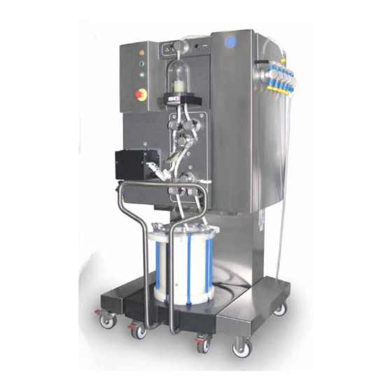
3 System description 3.2 Layout Layout ÄKTA ready Part Function ÄKTA ready cabinet unit ÄKTA ready flow kit (ordered separately) Column trolley ReadyToProcess column (ordered separately) ÄKTA ready Operating Instructions 28960345 AD... - Page 37 3 System description 3.2 Layout ÄKTA ready gradient Part Function ÄKTA ready gradient pump ÄKTA ready gradient flow section ÄKTA ready Operating Instructions 28960345 AD...
- Page 38 3 System description 3.2 Layout Components on system cabinet — front The drawing below shows the location of components on the ÄKTA ready cabinet. The cabinet is shown without the cabinet door and with a flow kit mounted. (Components of the flow kit are described in Flow kit components, on page 42.) Part...
- Page 39 3 System description 3.2 Layout Part Component ID tag Function POWERindica- Shows flashing green light during initial com- munication connection with UNICORN soft- ware, when power is switched on. Steady green light when power is on and communi- cation is established. EMERGENCY Stops the pump and places the system in STOP button...
- Page 40 3 System description 3.2 Layout Part Component ID tag Function Installation HS-5 Used for releasing and engaging valves dur- switch ing flow kit and column installation. Three different positions: FLOW KIT INSTALL: Opens all valves. User can manually open/close valve locks. RUN: Engages all valves.
- Page 41 3 System description 3.2 Layout Part Function POWER SUPPLY, System power cable (cable mounted) PNEUMATIC AIR SUPPLY, Compressed air connector SYSTEM COMPUTER, Ethernet network connector CUSTOMER I/O, User I/O Instructions for connecting the system For instructions on how to connect the system, see Section 4.6 Connections, on page ÄKTA ready Operating Instructions 28960345 AD...
- Page 42 3 System description 3.2 Layout Flow kit components ÄKTA ready uses flow kits that include all the necessary tubing, from inlet to outlet, in- cluding flow cells, air trap, column connection tubing, and pump tubing. Specifications regarding the flow kits, including materials and chemical resistance tables, are found in Chapter 14 Reference information, on page201.
- Page 43 3 System description 3.2 Layout Part Component ID tag Function Inlet manifold XV-001 to Manifold with 6 inlets corresponding to valves XV-006 XV-001 to XV-006. 25 mm TRI-Clamp™ (TC) connectors. Pump tubing Double pump tubing for mounting in the peristaltic pump. Double tubing increases ef- ficiency and reduces pulsation.
- Page 44 3 System description 3.2 Layout Part Component ID tag Function Conductivity CE-101 Sensor measuring the conductivity of the liq- sensor uid. UV flow cell AE-131 Flow cell for UV detector AE-131. Flow cell for PT-113 Flow cell for safety pressure sensor PT-113, pressure sen- which measures pressure after the sensors.
-
Page 45: Flow Chart
3 System description 3.3 Flow chart Flow chart Chart and components The liquid flow through ÄKTA ready is illustrated in the chart below. (Black: standard components; Red: optional components) HV-301 XV-056 P-202 XV-055 AT-221 XV-054 XV-053 XV-052 PT-111 PT-112 FE-141 CE-101 PT-113 XV-051 XV-001... - Page 46 3 System description 3.3 Flow chart Part Function XV-051 to XV-056 Outlet 1 to 6, grouped in Outlet Manifold PT-111 to PT-113 3 Pressure sensors cells AE-121 pH electrode (optional) FE-141 Flow meter cell TE-161 Temperature sensor CE-101 Conductivity sensor AE-131 UV cell AT-221...
- Page 47 3 System description 3.3 Flow chart From column to outlet Stage Description Downstream of the column, the liquid passes through a second pressure sensor cell (PT-112), which has an integrated flow cell for a pH electrode (AE-121). The liquid then continues through: a flow meter cell (FE-141) with integrated temperature sensor (TE-161), •...
-
Page 48: Equipment
3 System description 3.4 Equipment Equipment Pinch valves Pinch valves are used to control the path of the liquid flow through the system. There are 19 pinch valves in total. The valves have manually operated safety locks keeping the tubing in place and pre- venting the valves from accidentally closing during flow kit installation. - Page 49 3 System description 3.4 Equipment Pressure cells The pressure cells in the ÄKTA ready flow kits are designed with a flexible membrane that is brought into contact with a transducer (load cell) on the system cabinet for measurement of fluid pressure. There are three pressure cells, continuously mea- suring the pressure of the liquid: Pressure cell...
- Page 50 3 System description 3.4 Equipment pH electrode (optional) The pH electrode, AE-121, is an optional accessory (see Section 14.4 Ordering information, on page 210). The electrode can be mounted in a holder on top of pressure cell PT-112. When a flow kit is delivered, a dummy is located in the pH electrode holder. Unlike the rest of the flow kit, the pH electrode has not been autoclaved or subjected to gamma radiation at delivery and must therefore be cleaned by the user.
- Page 51 3 System description 3.4 Equipment Conductivity sensor The conductivity sensor, CE-101, is included with the flow kit (for all other sensors, the flow kit includes only the flow cells). The conductivity sensor is located after the flow meter cell in the flow path. It is primarily used to verify the conductivity of buffer solutions. Conductivity measurement is temperature compensated and thus dependent on correct temperature readings.
-
Page 52: Unicorn Control System
Information on how to use UNICORN can be obtained from the UNICORN documentation and available tutorials. This manual does not cover how to use UNICORN. Contact your local GE Healthcare representative for advice if required. System networks UNICORN can be installed on a stand-alone computer to control one to four locally attached systems. - Page 53 3 System description 3.5 UNICORN control system Software modules The UNICORN control software consists of four modules: Module Function In UNICORN 5: UNICORN Manager File handling and administration tasks; for ex- ample, definition of systems and managing In UNICORN 7: Administration user profiles.
- Page 54 3 System description 3.5 UNICORN control system Alarms Signals If equipment is connected that has lower limits than the system, the alarm levels must be set accordingly. If an analog or digital signal passes the predetermined alarm level, several things happen at once: •...
-
Page 55: Installation
• Personal protection, on page 16 NOTICE ÄKTA ready shall be installed and prepared by personnel from GE Healthcare or third party authorized by GE Healthcare. Contact GE Healthcare if you require re-installation at a new site. ÄKTA ready Operating Instructions 28960345 AD... - Page 56 4 Installation In this chapter This chapter contains the following sections: Section See page 4.1 Included in the delivery 4.2 Site requirements 4.3 Transport 4.4 Unpacking 4.5 Positioning the system 4.6 Connections ÄKTA ready Operating Instructions 28960345 AD...
-
Page 57: Included In The Delivery
4 Installation 4.1 Included in the delivery Included in the delivery General ÄKTA ready is delivered in a wooden box containing: • the system cabinet, • a column trolley, • a smaller box containing an accessory kit, system documentation folder and user documentation. -
Page 58: Site Requirements
4 Installation 4.2 Site requirements Site requirements Precautions WARNING Explosive environment. The product is not approved for work in a potentially explosive atmosphere, in areas classified as Zone 0 to Zone 2 according to IEC 60079-10 2002. The product does not fulfill the requirements of the ATEX Directive. - Page 59 4 Installation 4.2 Site requirements Compressed air • Dry and particle free air • Airflow 50 Nl/min • Working pressure 5.5 to 10 bar • Air hose connector, a 5 m long air hose with an inner diameter of 7.5 mm is supplied with the system.
-
Page 60: Transport
4 Installation 4.3 Transport Transport Crate dimensions The ÄKTA ready is delivered in a crate. The crate dimensions are different if it is an ÄKTA ready or an ÄKTA ready gradient. ÄKTA ready ÄKTA ready gradient 190 cm 190 cm 190 cm 190 cm 110 cm... - Page 61 4 Installation 4.3 Transport Release wheels to move ÄKTA ready The ÄKTA ready can be rolled on hard and level surface with brakes on wheels released. Use the handle to move ÄKTA ready Use the handle on the left side of the cabinet to maneuver ÄKTA ready. ÄKTA ready Operating Instructions 28960345 AD...
- Page 62 4 Installation 4.3 Transport Lifting ÄKTA ready There are no lifting hooks on ÄKTA ready. Use a forklift or a pallet jack with a minimum capacity of 400 kg for lifting the system. Appropriate safety precautions should be fol- lowed. CAUTION Do not attempt to lift the system by the handle on the left side of the system cabinet.
- Page 63 4 Installation 4.3 Transport Center of gravity The center of gravity for ÄKTA ready is indicated with a dashed and dotted, vertical line in the drawings below. Note: The line is located slightly towards the back of the cabinet. This must be taken into consideration when moving or lifting the cabinet.
- Page 64 4 Installation 4.3 Transport Positioning forks • • ÄKTA ready Operating Instructions 28960345 AD...
-
Page 65: Unpacking
Check the equipment for damage before starting assembly and installation. There are no loose parts in the crate. All parts are either mounted on the system or located in the accessory kit box. If any damage is found, document the damage, and contact your local GE Healthcare representative. Safety Precautions WARNING Personal Protective Equipment (PPE). -
Page 66: Positioning The System
4 Installation 4.5 Positioning the system Positioning the system Note: The area required at the production location for ÄKTA ready is 280 x 300 cm, allowing for 100 cm of free space on all sides of the system. The ÄKTA ready gradient needs slightly more free space (280 x 316 cm). The space is required to make room for containers and hoses, and to allow for easy ac- cess to the power switch and to connectors on the back of the unit. -
Page 67: Connections
Do not turn on the Mains power switch before all connections are made. Power connection The mains power supply must be connected and configured by authorized service per- sonnel. Please contact your GE Healthcare representative. Compressed air NOTICE Check that the Pressure Control Regulator for the system air supply is set to the pressure stated in the specifications. - Page 68 4 Installation 4.6 Connections CAUTION Make sure that correct air pressure is always maintained. Too high or too low air pressure may be hazardous and may cause erroneous results and leakage. Instruction Step Action Connect your compressed air supply to the air input connector on the back of the system, labeled PNEUMATIC AIR SUPPLY.
- Page 69 4 Installation 4.6 Connections Computer Requirements WARNING Installing the computer. The computer must be installed and used according to the instructions provided by the manufacturer of the computer. UNICORN is the controlling software for ÄKTA ready. It is recommended that the computer used is dedicated to UNICORN and related software.
- Page 70 4 Installation 4.6 Connections Customer I/O Connector The CUSTOMER I/O connector (C1 in figure below) is located on the left side of the system cabinet, beneath the inlet valves. The connector is a 15-pole IP67-proof Dsub male connector. A female mating connector containing a screw terminal block with water tight housing is supplied with the system.
- Page 71 4 Installation 4.6 Connections Connection for air sensors The air sensors are connected to the CUSTOMER I/O as shown in the illustration below. Finishing installation Verifying connections Finish installation of ÄKTA ready by verifying that the system is properly connected to mains power, to compressed air supply, and to the computer.
- Page 72 4 Installation 4.6 Connections Establishing computer connection Step Action Turn on ÄKTA ready using the Mains power switch, located on the left side of the cabinet. Check that the green POWER lamp on the front of the unit lights up (bottom lamp in figure).
- Page 73 4 Installation 4.6 Connections Installing the barcode reader The barcode reader is installed and configured as described below. Note: Installation requires barcodes to be scanned from the Quick Start Guide sup- plied with the barcode reader. If the Quick Start Guide is lost, it can be down- loaded from the barcode reader manufacturer's web site.
-
Page 74: Starting Äkta Ready
5 Starting ÄKTA ready Starting ÄKTA ready About this chapter This chapter describes how to start and log on to UNICORN and ÄKTA ready. Precautions WARNING Before attempting to perform any of the procedures described in this chapter, you must read and understand all contents of the corresponding section(s) in the Section 2.1 Safety precautions, on page 15... -
Page 75: Start And Log On To Unicorn
5 Starting ÄKTA ready 5.1 Start and log on to UNICORN Start and log on to UNICORN UNICORN software The UNICORN control software is delivered with the system. UNICORN should be installed on a PC (optional) with Microsoft Windows operating system. Refer to the UNICORN manuals for software installation instructions. -
Page 76: Start The System
5 Starting ÄKTA ready 5.2 Start the system Start the system General ÄKTA ready is normally left switched on between runs. The unit is switched off only during monthly maintenance and repair, or when not in operation for a longer period of time (more than a few days). -
Page 77: Flow Kit Installation
6 Flow kit installation Flow kit installation About this chapter This chapter presents the different flow kits that can be used with the ÄKTA ready, and describes how to install an ÄKTA ready flow kit. Much of the information in this chapter is also available in the ÄKTA ready installation wizard (part of supplied software). -
Page 78: Äkta Ready Flow Kits
6 Flow kit installation 6.1 ÄKTA ready flow kits ÄKTA ready flow kits Three parts ÄKTA ready flow kits are delivered in three parts. Each of the three parts constituting the flow path are sanitized and ready for use with the ÄKTA ready. Part Function Inlet manifold... - Page 79 Both flow kits use 25 mm TC connectors for connecting to inlet and outlet containers, pump tubing, and column. NOTICE Only use flow kits, supplied by GE Healthcare. Specifications for ÄKTA ready flow kits are found in ÄKTA ready flow kit specifications, on page 203.
-
Page 80: Unpacking The Flow Kit
6 Flow kit installation 6.2 Unpacking the flow kit Unpacking the flow kit Flow kit package To protect against contamination, ÄKTA ready flow kits are delivered in double plastic bags. The flow kit package contains the following items: • The main part of the flow kit and the inlet manifold (6 inlets). The main part includes air trap, column connection tubing, sensor flow cells, and outlet manifold (6 outlets). -
Page 81: Mounting The Flow Kit
6 Flow kit installation 6.3 Mounting the flow kit Mounting the flow kit Introduction This section contains a step-by-step description of how to install a flow kit onto the ÄKTA ready cabinet. The procedure described here is an extended version of the proce- dure described in the Flow Kit Installation part of the ÄKTA ready Installation Wizard. - Page 82 6 Flow kit installation 6.3 Mounting the flow kit Before starting System setup • In UNICORN 5 the component list is reached by clicking System Setup on the Admin- istration menu in the UNICORN Manager • In UNICORN 7, in the Administration module, click System Properties and then click Edit in the System Properties dialog box.
- Page 83 6 Flow kit installation 6.3 Mounting the flow kit End caps At delivery, all connectors on the flow kit, except those on the pump tubing, are covered by protective end caps. The caps are removed during installation. Remember to save the end caps as they are used to seal the tubing when the flow kit is removed and dis- posed of (see Section 11.4 After the run, on page...
- Page 84 6 Flow kit installation 6.3 Mounting the flow kit Open the installation wizard Step Action UNICORN 5: In the ÄKTA ready System Control module, on the File menu, • click Instant Run and then click Run in the dialog box shown. UNICORN 7: In the ÄKTA ready Method Editor module, on the File menu, •...
- Page 85 6 Flow kit installation 6.3 Mounting the flow kit Open all safety locks on pinch valves The safety locks keep the pinch valves locked in an open position, thereby preventing injuries due to, for instance, a faulty compressed air supply. To open them: Step Action Start the installation by turning...
- Page 86 6 Flow kit installation 6.3 Mounting the flow kit Remove the pump lid Step Action Locate the bolts holding the pump lid. Use the supplied 10 mm wrench, located on the in- side of the front cabinet door, to rotate the right-hand bolt counter-clockwise, and the left- hand bolt clockwise, until both are fully open.
- Page 87 6 Flow kit installation 6.3 Mounting the flow kit Open pressure cell holders Step Action Locate the three pressure cell PT-113 holders for pressure sensors PT- 111, PT-112, and PT-113. PT-112 PT-111 Release (but do not remove) the screws on the latches, and turn the latches open.
- Page 88 6 Flow kit installation 6.3 Mounting the flow kit Mount the inlet manifold Step Action Open the plastic package containing the inlet manifold and main part of the flow kit. Retrieve the inlet manifold and mount it on the system cabinet by inserting each inlet tubing into the correspond- ing inlet pinch valve (XV-001 to XV- 006).
- Page 89 6 Flow kit installation 6.3 Mounting the flow kit Connect and mount the pump tubing Step Action Open the plastic bag containing the pump tubing and place the tubing on top of the pump rollers with the larger connector block (the block with the connec- tor for the main part of the flow kit) to the right.
- Page 90 6 Flow kit installation 6.3 Mounting the flow kit Step Action To attach the pump lid: Press down the pump lid • with one hand, Secure it by rotating the left • and right bolts counter- clockwise and clockwise, using the supplied wrench (also see Remove the pump lid, on page...
- Page 91 6 Flow kit installation 6.3 Mounting the flow kit Mount the main part tubing Step Action Pinch valves: Insert the tubing into the air trap valves (1-3 in figure), the column valves (4-6), and the air release valve (7). Proceed in the order indicated by the numbers in the figure (i.e., start with the air trap valves).
- Page 92 6 Flow kit installation 6.3 Mounting the flow kit Step Action Flow meter cell: Align the holes in the body of the flow meter cell (FE-141) with the two knobs on the cabinet (see 1 and 2 in figure) and push the cell into place.
- Page 93 6 Flow kit installation 6.3 Mounting the flow kit Step Action Conductivity cell: Unscrew the protective cap (1) on the system cabinet´s conduc- tivity connector. Connect the conductivity sensor by screwing its cable connector (2) onto the connector on the system cabinet.
- Page 94 6 Flow kit installation 6.3 Mounting the flow kit Step Action pH electrode: Unscrew the plastic fastening nut (1) on top of pressure cell (PT-112) and pull out the dummy from the electrode holder (2). Release the pH cable from its storage position by unscrewing the lower cable connector from the system cabinet.
- Page 95 6 Flow kit installation 6.3 Mounting the flow kit Mount the outlet tubing Step Action Mount the outlet manifold by insert- ing each outlet tube into the corre- sponding outlet pinch valve (valves XV-051 to XV-056). Do not yet remove the end caps.
- Page 96 6 Flow kit installation 6.3 Mounting the flow kit NOTICE The end of the air trap tubing should be directed away from the operator (preferably, it should be connected to a waste hose). A component test should always be performed after mounting a new flow kit. If the in- stallation wizard is used, a component test is automatically included in the installation procedure.
-
Page 97: Äkta Ready Gradient
7 ÄKTA ready gradient ÄKTA ready gradient About this chapter This chapter provides an overview of the details of ÄKTA ready gradient. It describes how to install the ÄKTA ready gradient flow section. It also provides an instruction how to calibrate the pump. Gradient linearity is ±4% between 10% to 90%. -
Page 98: Äkta Ready Gradient Pump
7 ÄKTA ready gradient 7.1 ÄKTA ready gradient pump ÄKTA ready gradient pump Introduction ÄKTA ready gradient pump consists of a stainless steel box containing a pump motor, a pump head and electrical cables. It also includes a motor driver installed inside the ÄKTA ready cabinet. -
Page 99: Äkta Ready Gradient Flow Section
7 ÄKTA ready gradient 7.2 ÄKTA ready gradient flow section ÄKTA ready gradient flow section Two parts ÄKTA ready gradient flow section are delivered as two parts. Each of the two parts con- stituting the flow parts are autoclaved and ready for use with ÄKTA ready. Part Function Pump tubing... - Page 100 Both flow kits use 25 mm TC connectors for connecting to inlet and outlet containers, pump tubing, and column. NOTICE Only use ÄKTA ready flow sections, supplied by GE Healthcare. Specifications for ÄKTA ready flow kits are found in ÄKTA ready gradient section specifi- cations, on page 204.
- Page 101 7 ÄKTA ready gradient 7.2 ÄKTA ready gradient flow section Step Action Place the ÄKTA ready pump tubing on the ÄKTA ready gradient pump (P-202). Take the ÄKTA ready gradient pump tubing from the ÄKTA ready gradient flow section package. For a description of the content of the ÄKTA ready gradient flow section package see Two parts, on page...
- Page 102 7 ÄKTA ready gradient 7.2 ÄKTA ready gradient flow section Step Action Connect the other end of the jumper tubing to the right side of the ÄKTA ready gradient pump tubing (placed on the the system pump). Connect the inlet manifold to the left side of the ÄKTA ready gradient pump tubing placed on the ÄKTA ready system pump (P-201) using a TC clamp.
-
Page 103: Calibrate And Operate The Äkta Ready Gradient Pump
7 ÄKTA ready gradient 7.3 Calibrate and operate the ÄKTA ready gradient pump Calibrate and operate the ÄKTA ready gradient pump Introduction The calibration procedure compensates for differences in capacity of pump A (P-201) and pump B (P-202) at a given motor speed, as a result of pump tubing position and properties. - Page 104 7 ÄKTA ready gradient 7.3 Calibrate and operate the ÄKTA ready gradient pump Set up for calibration The set up for calibration procedure is run to ensure that no air bubbles are present in the system tubings. A column should be connected to make the calibration conditions similar to those of a real run.
- Page 105 7 ÄKTA ready gradient 7.3 Calibrate and operate the ÄKTA ready gradient pump Calibration Step Action For calibration, set Flow to at least 20 l/h for LowFlow Kit and 40 l/h for HighFlow Kit. Set Column under FlowPath to Inline. When flow signal is stable at set flow rate, select P201Gain under Pump and click Execute.
- Page 106 7 ÄKTA ready gradient 7.3 Calibrate and operate the ÄKTA ready gradient pump Step Action Select P202Gain under Pump, click Execute when flow signal is stable at set flow rate. Select FlowCompensation under Pump and click ON and let the calibration procedure compensate for differences between the capacity of pumps A (P-201) and B (P-202).
-
Page 107: Component Test
8 Component test Component test About this chapter This chapter describes the component test, which should always be run after installing a new flow kit to secure the functionality of the different flow cells. The structure and content of a component test report is presented, and troubleshooting after a failed test is discussed to secure the functionality of the different flow cells. -
Page 108: Run A Component Test
8 Component test 8.1 Run a component test Run a component test General The component test consists of a number of steps to assure correct function of the components of the ÄKTA ready, in particular the sensors. The points being tested are: •... - Page 109 8 Component test 8.1 Run a component test Stage Description After: After the test has finished, the test results can be printed. The results printout shows all registered flow kit bar codes, installation procedures, notes, and test results. If page 8 does include any warning or other text the test failed. If all flow cell tests passed the system can be used.
- Page 110 8 Component test 8.1 Run a component test Step Action Remove the protective end cap from inlet tube 5 (arrow), and connect the test solution. Note: If ÄKTA ready gradient is installed use inlet tube 7. Remove the protective end cap from outlet 6 (arrow), and connect a waste hose to this outlet.
- Page 111 8 Component test 8.1 Run a component test Enter installation information After pressing Run in the installation wizard, you are directed to the UNICORN start protocol with panels containing data about the installation. Start Notes In the first panel, Start Notes, is a text area where notes about the installation can be entered.
- Page 112 8 Component test 8.1 Run a component test Running the component test A component test takes approximately 10 minutes. The progress of the test can be fol- lowed in UNICORN, in charts showing the response curves for different sensors. During the run, two things will happen that will require user attention: •...
-
Page 113: The Test Report
8 Component test 8.2 The test report The test report General Information about an installation including the results from the component test are stored and can be compiled into a printed report. If the option Print report automatically was chosen initially in the installation wizard (Open the installation wizard, on page 84), the results from the component test run will be available in the form of a printed report produced immediately after the test has fin-... - Page 114 8 Component test 8.2 The test report Evaluation notes Evaluation notes are notes entered after the test is finished. • In the UNICORN 7 Evaluation module, click View, click Run Record and then click the Notes tab. • In the UNICORN 5 Evaluation module or the UNICORN 7 Evaluation Classic module, on the View menu, click Documentation and then click the Notes tab.
- Page 115 8 Component test 8.2 The test report Results from component test The section Results from component test contains the test results. The results are pre- sented in the form of charts showing the response over time for each of the different sensors.
- Page 116 8 Component test 8.2 The test report Last page The last page of the report has the header Comments, under which there is room for comments on the paper copy of the report. The page also contains the signature fields Performed by and Approved by, where date, name and position can be specified.
-
Page 117: Troubleshooting A Failed Component Test
8 Component test 8.3 Troubleshooting a failed component test Troubleshooting a failed component test Troubleshooting Should a component fail the component test, troubleshooting should be done to establish the cause of failure and allow for correction of the problem. A failing component is identified in the report or result file by the text TEST FAILED in the component chart. - Page 118 8 Component test 8.3 Troubleshooting a failed component test Pressure sensors The most likely reason for pressure sensors to return incorrect values is incorrect mounting: • Make sure that each flow cell is properly aligned with its adapter. Check that there is no gap between flow cell and adapter.
- Page 119 8 Component test 8.3 Troubleshooting a failed component test Conductivity Problems with conductivity can be caused by: Problem Solution Poor connection. Make sure the conductivity sensor's connector cable is properly connected to the system cabinet (see Mount the main part tubing, on page 91).
- Page 120 8 Component test 8.3 Troubleshooting a failed component test Problems with UV can be caused by: Problem Solution Insufficient light trans- Check that the UV cell and sensor windows are clean and mission. dry. Wipe with soft tissue if necessary. Incorrect mounting of Make sure that the UV cell is pushed all the way in.
- Page 121 4 Close the valve lock. 5 Turn the installation switch back to RUN. If problems remain If problems continue after checking the points above, please contact your GE Healthcare representative (contact information on back cover). ÄKTA ready Operating Instructions 28960345 AD...
-
Page 122: Column Installation
9 Column installation Column installation About this chapter This chapter describes how to install a column on the ÄKTA ready. Much of the information in this chapter is available under Column Installation of the ÄKTA ready installation wizard (part of supplied software). The chapter also contains instructions for running an efficiency test and for column rinsing. - Page 123 9 Column installation In this chapter This chapter contains the following sections: Section See page 9.1 Columns 9.2 Installing a column 9.3 Optional column test 9.4 Optional column rinsing 9.5 Adding columns to the column list ÄKTA ready Operating Instructions 28960345 AD...
-
Page 124: Columns
More information about columns and separation media can be found in the Product catalog on the GE Healthcare web page (address on back cover). ÄKTA ready Operating Instructions 28960345 AD... - Page 125 9 Column installation 9.1 Columns ReadyToProcess columns ReadyToProcess columns are pre- packed, pre-qualified, and pre-sanitized chromatography columns. They are available with a range of BioProcess™ media, such as: Capto™ adhere • Capto Core 700 • Capto DEAE • Capto L (non-sanitized) •...
- Page 126 210. RTP columns packed with Capto and Sepharose 6FF media can be requested by GE Healthcare even if not listed in ordering list. ReadyToProcess columns are qualified by efficiency testing and are delivered with indi- vidual certificates. Testing includes for example analysis of theoretical plates per m...
-
Page 127: Installing A Column
9 Column installation 9.2 Installing a column Installing a column Introduction The steps described in this section follow the steps in the Column Installation trail in the ÄKTA ready Installation Wizard. Refer also to the information provided in the instruc- tions for the chosen column. - Page 128 9 Column installation 9.2 Installing a column Open the column installation wizard Open the Column Installation trail of the ÄKTA ready Installation wizard. Step Action UNICORN 5: In the ÄKTA ready System Control module, on the File menu, • click Instant Run and then click Run in the dialog box shown. UNICORN 7: In the ÄKTA ready Method Editor module, on the File menu, •...
- Page 129 9 Column installation 9.2 Installing a column Select a column type The first panel of the column installation wizard is Initial settings. The Initial settings panel contains fields for selecting a column type. Note: In UNICORN 7 there is no predefined list with column types. The method created with the installation wizard will contain default column parameters.
- Page 130 9 Column installation 9.2 Installing a column Step Action From the Column list, select the column type that will be used. The list is limited to columns relevant for the technique selected in the previous step. If All was selected, the list will include all columns available, regardless of technique.
- Page 131 9 Column installation 9.2 Installing a column Step Action In the Phase Properties tab, select the newly created column in the Column type list. In the Method Outline click User Defined. In the Phase Properties tab edit the values for the different variables (e.g. pressure limits) to fit the column and media used.
- Page 132 9 Column installation 9.2 Installing a column Connect a column CAUTION Before use, check that the column is not damaged or otherwise defective. Damaged or defective columns may leak. Follow the instructions below to connect a column to the system (connectors should be treated aseptically when connecting): Step Action...
- Page 133 9 Column installation 9.2 Installing a column Finish the installation Step Action Turn the Installation switch in the upper, right corner of the system cabinet to the COLUMN INSTALL position. This will open a free passage from air trap to column.
- Page 134 9 Column installation 9.2 Installing a column A report similar to the flow kit installation report can also be produced for a column in- stallation. The report can be either automatically produced, or manually created by se- lecting the report format AKTA ready_Column in the Report dialog box in the UNICORN Evaluation module.
-
Page 135: Optional Column Test
9 Column installation 9.3 Optional column test Optional column test Introduction A method for efficiency testing of columns can be created in the UNICORN Method Editor (from the provided method template), or an efficiency test can be run in connection with installation of a column, using the installation wizard, as described in Section 9.2 Installing a column, on page... - Page 136 9 Column installation 9.3 Optional column test Running the column efficiency test A column efficiency test is started by clicking Start in the UNICORN Result Name panel in the Start Protocols dialog box displayed immediately after finishing the installation wizard. The test is performed using 100 cm/h liquid velocity and normally takes approx- imately 30 minutes.
- Page 137 9 Column installation 9.3 Optional column test Test results Results from an efficiency test are stored and processed in a similar way as results from a component test. The results are stored at a user-defined location, and they can be compiled and presented in the form of a printed report using report format AKTA ready_Column_T, which includes results from the efficiency test in addition to the installation information in report format AKTA ready_Column.
-
Page 138: Optional Column Rinsing
9 Column installation 9.4 Optional column rinsing Optional column rinsing Column rinsing A method for column rinsing may be custom designed by the user, or the predefined method for column rinsing can be used. The predefined method is included as an optional step in the column installation wizard. -
Page 139: Adding Columns To The Column List
9 Column installation 9.5 Adding columns to the column list Adding columns to the column list Adding columns It is possible to add columns, for example “RTP columns on request”, to the ÄKTA ready installation wizard. Follow the steps below to add a new column to the UNICORN column list. - Page 140 9 Column installation 9.5 Adding columns to the column list Step Action The added column is now be available in the ÄKTA ready wizard. ÄKTA ready Operating Instructions 28960345 AD...
-
Page 141: Creating A Method
For information about methods in general, and for detailed information about the Method Editor, please see the UNICORN manuals. Courses in UNICORN system control, including method design, are available from Fast Trak Training & Education. Contact your local GE Healthcare representative for informa- tion. In this chapter... -
Page 142: The Method Editor
10 Creating a method 10.1 The Method Editor 10.1 The Method Editor In this section This section contains the following subsections: Section See page 10.1.1 Introduction to the Method Editor 10.1.2 Method Editor layout 10.1.3 Other Method Editor features ÄKTA ready Operating Instructions 28960345 AD... -
Page 143: Introduction To The Method Editor
10 Creating a method 10.1 The Method Editor 10.1.1 Introduction to the Method Editor 10.1.1 Introduction to the Method Editor Description The Method Editor is used to build new methods in a step-by-step manner using blocks and instructions as building elements. The editor can also be used to edit already existing methods. - Page 144 10 Creating a method 10.1 The Method Editor 10.1.1 Introduction to the Method Editor Opening the Method Editor Open the Method Editor window from the UNICORN Manager module by clicling Method Editor it in the task bar at the bottom of the screen. Step Action Click the Customize panes icon in the...
-
Page 145: Method Editor Layout
10 Creating a method 10.1 The Method Editor 10.1.2 Method Editor layout 10.1.2 Method Editor layout Text pane The Text pane contains an overview of the method in the form of an expandable list with all blocks and instructions in the method. Blocks are marked by blue square symbols. - Page 146 10 Creating a method 10.1 The Method Editor 10.1.2 Method Editor layout • Buttons — There are four buttons: Insert, Change, Replace, and Delete. Change, Replace and Delete affect the instruction or block currently selected in the Text pane. While Insert adds a new instruction before, or after (if it has the same breakpoint as an old instruction), the current selection.
-
Page 147: Other Method Editor Features
10 Creating a method 10.1 The Method Editor 10.1.3 Other Method Editor features 10.1.3 Other Method Editor features Introduction The method created in the following chapter covers the most basic aspects of how a method is built. Follow this example to learn the basics of designing a chromatography method. - Page 148 10 Creating a method 10.1 The Method Editor 10.1.3 Other Method Editor features Manual calibration of UV stray light When the stray light calibration is performed a warning message is displayed. The warning message can be disabled. Follow the instruction below to perform a UV stray light calibration. Step Action Click Alarms&Mon and then StraylightCalib_UV_AT_131 in the Instructions...
- Page 149 10 Creating a method 10.1 The Method Editor 10.1.3 Other Method Editor features Disable fine tuning flowmeter failed message When the flow measuring algorithm fails to make a fine tuning of the flow measurement, a Fine_tuning_flowmeter_failed message is displayed. This is mainly a warning that the accuracy of the flow measurement is slightly decreased.
- Page 150 10 Creating a method 10.1 The Method Editor 10.1.3 Other Method Editor features Step Action The report mode can also be changed only for the present run. After the run the setting is restored to the previous one. Click Alarms&Mon and then Fine_Tune_Fail_Report in the Manual menu. If you click Enable and after that Execute the Fine_tuning_flowme- •...
- Page 151 10 Creating a method 10.1 The Method Editor 10.1.3 Other Method Editor features Pressure flow control Follow the instructions to perform pressure flow control with optimal functionality. Step Action Select PressureFlowControl and enable the function, then select PressureFlowLimit. Select the pressure and the pressure sensor that should control the pressure. Select the flow rate, and the pressure flow control will work as expected.
-
Page 152: An Example Of Using The Method Editor
10 Creating a method 10.2 An example of using the Method Editor 10.2 An example of using the Method Editor About the example Creating a method involves creating and naming the method, and adding blocks and instructions to it. In this section, a simple example is used to illustrate the different steps in the procedure. -
Page 153: Creating The Method And Selecting A Column
10 Creating a method 10.2 An example of using the Method Editor 10.2.1 Creating the method and selecting a column 10.2.1 Creating the method and selecting a column Start out by creating an empty method and selecting a column: Step Action In the Method Editor, click New on the File menu. -
Page 154: Block 1: Opening Valves
10 Creating a method 10.2 An example of using the Method Editor 10.2.2 Block 1: Opening valves 10.2.2 Block 1: Opening valves The first block in the method will open valves in the flow path: Step Action In the Method Editor. click New on the Block menu. - Page 155 10 Creating a method 10.2 An example of using the Method Editor 10.2.2 Block 1: Opening valves Step Action Following the same general procedure as in step 3, insert also these instruc- tions into the block: At time 0.10, set instruction AirTrap to Bypass. •...
-
Page 156: Block 2: Auto-Zeroing Pressure Sensors
10 Creating a method 10.2 An example of using the Method Editor 10.2.3 Block 2: Auto-zeroing pressure sensors 10.2.3 Block 2: Auto-zeroing pressure sensors Step Action Follow the general procedure used for block 1 to create a new block. Name the block, for instance, MyAu- , and set its Base tozeroPressure... -
Page 157: Block 3: Setting Pid Parameters
10 Creating a method 10.2 An example of using the Method Editor 10.2.4 Block 3: Setting PID parameters 10.2.4 Block 3: Setting PID parameters Whenever an automated process step requires control of flow, the UNICORN control software employs PID-type controllers (see Section 14.5 PID control, on page 214). -
Page 158: Block 4: Filling The Flow Kit
10 Creating a method 10.2 An example of using the Method Editor 10.2.5 Block 4: Filling the flow kit 10.2.5 Block 4: Filling the flow kit Next create a block for filling the flow kit, including the air trap, with liquid. This is done by pumping liquid through the flow path until a stable flow is achieved, or until a time- out (a maximum time) is reached. - Page 159 10 Creating a method 10.2 An example of using the Method Editor 10.2.5 Block 4: Filling the flow kit Nested block: Filling the air trap Create a separate block for filling the air trap. Make this a nested block, placed inside the MyFillFlowKit block.
-
Page 160: Block 5: Equilibration
10 Creating a method 10.2 An example of using the Method Editor 10.2.6 Block 5: Equilibration 10.2.6 Block 5: Equilibration The next block is for equilibrating the column: Step Action Create a new block named , and set its base to Same MyEquilibration as main (which in this case is column volumes). -
Page 161: Block 6: Sample Load
10 Creating a method 10.2 An example of using the Method Editor 10.2.7 Block 6: Sample load 10.2.7 Block 6: Sample load The block responsible for sample load has the sample volume as finishing criterion. Flow and valve positions (air trap inline and column inline) are maintained from the previous block and do not have to be redefined. - Page 162 10 Creating a method 10.2 An example of using the Method Editor 10.2.7 Block 6: Sample load The MySampleLoad block is now defined to run 42.8 liters of sample, after first having au- to-zeroed UV, set an injection mark, and filled the flow kit with sample liquid.
-
Page 163: Block 7: Washing Unbound Sample
10 Creating a method 10.2 An example of using the Method Editor 10.2.8 Block 7: Washing unbound sample 10.2.8 Block 7: Washing unbound sample After applying the sample you need to define instructions to wash out any unbound sample from the column. Step Action Create a block named... -
Page 164: Block 8: Elution
10 Creating a method 10.2 An example of using the Method Editor 10.2.9 Block 8: Elution 10.2.9 Block 8: Elution Similar to sample load and washing in previous blocks, elution is controlled by UV re- sponse. You thus need to define two watch blocks with UV-based criteria for starting and stopping the elution process. - Page 165 10 Creating a method 10.2 An example of using the Method Editor 10.2.9 Block 8: Elution The Elution block Now that you have defined and saved the Fraction and Fraction_Stop blocks, proceed by defining the elution block: Step Action Create a block named and set its Base to Volume.
-
Page 166: Block 9: Regeneration
10 Creating a method 10.2 An example of using the Method Editor 10.2.10 Block 9: Regeneration 10.2.10 Block 9: Regeneration The last step for a complete chromatog- raphy cycle is to regenerate the column. This is done by defining a block with in- structions for selecting inlet and outlet, and for setting the air trap and column inline. -
Page 167: Saving The Method
10 Creating a method 10.2 An example of using the Method Editor 10.2.11 Saving the method 10.2.11 Saving the method Finish by saving your new method. Click Save (or Save As) on the File menu in the Method Editor to open the Save as dialog box. In this dialog box you specify the folder in which to save the method, and also the system and technique it is intended for. -
Page 168: Creating A Column Efficiency Test
10 Creating a method 10.3 Creating a column efficiency test 10.3 Creating a column efficiency test General Methods for testing of column efficiency can be created using the method wizard available in the Method Editor. Opening the wizard The wizard is opened from the UNICORN Method Editor module by clicking Method Wizard on the File menu. - Page 169 10 Creating a method 10.3 Creating a column efficiency test Editing the method A method created with the method wizard can be later edited in the Method Editor via, for instance, the Run Setup dialog box. Open the dialog box by clicking Run Setup on the View menu.
-
Page 170: Run A Method
11 Run a method 11 Run a method About this chapter Running a method on ÄKTA ready is a largely automatic procedure. User interaction is mainly required in the preparation phase, which includes connecting the column and the required containers, and checking that all connections are correctly assigned and that flow kit type and volumes are correct. -
Page 171: Final Preparations Before A Run
11 Run a method 11.1 Final preparations before a run 11.1 Final preparations before a run Precautions WARNING • Hazardous substances and biological agents. When using hazardous chemical and biological agents, take all suitable protective measures, such as wearing protective glasses and gloves resistant to the substances used. - Page 172 11 Run a method 11.1 Final preparations before a run Connect containers Buffers Connect the buffer inlet tubing to the appropriate buffer containers. Check that there are sufficient buffer volumes available. Note: Significant differences in the liquid level (height of elevation), in between con- nected inlet/outlet lines and containers, may cause unintended mixing in be- tween the inlet/outlet lines if the valve switching time, (the time of overlap in open valves when switching inlets without pump stop), is selected too long.
- Page 173 11 Run a method 11.1 Final preparations before a run Eliminate switch time If the simultaneous opening of two valves as described above needs to be avoided, valve switching may be performed sequentially by stopping the pump operation, closing the first valve and opening the second valve.
- Page 174 11 Run a method 11.1 Final preparations before a run Prime the system Before starting a run, make sure that the flow path, including hoses to inlet containers, are filled with liquid and that no air bubbles remain in the system. The air trap can only remove small amounts of air.
-
Page 175: Starting A Run
11 Run a method 11.2 Starting a run 11.2 Starting a run General Starting a run is done from UNICORN, after first having checked that all inlets and outlets are correctly assigned, and that the volumes of inlet and outlet containers are correct. Starting Step Action... - Page 176 11 Run a method 11.2 Starting a run Monitoring The progress of the run can be viewed in detail in the UNICORN System Control module. Up to four different panels can simultaneously display different aspects of the run. To customize content and layout of a panel, right-click and then click Properties. By clicking Documentation and then Run notes it is possible to add notes during a run.
- Page 177 11 Run a method 11.2 Starting a run Ending Normal completion If no unexpected events occur during the run, UNICORN enters END state at method completion without need for user interaction. End before method has finished To end the run before the method has finished, click on the End button at the top of the Control module window.
-
Page 178: Viewing And Printing Results
11 Run a method 11.3 Viewing and printing results 11.3 Viewing and printing results General Results from a run are viewed in, and printed from, the UNICORN Evaluation module. Viewing results Step Action Locate the result file in the Files panel to the left in the Evaluation module. Double-click the result file. - Page 179 11 Run a method 11.3 Viewing and printing results Printing results Step Action Open the chromatogram you want to print in the Evaluation module. Click Print on the File menu. In the Print Chromatograms dialog box, select print format and layout op- tions.
-
Page 180: After The Run
11 Run a method 11.4 After the run 11.4 After the run General If flow kit and column should be disposed of, this must be done in accordance with local regulations. Preparing the flow kit and column for disposal involves washing the flow kit and column, draining any liquid from them, and remounting the protective caps they were delivered with. - Page 181 11 Run a method 11.4 After the run Step Action Remove the pump lid. Lift off the (still assembled) flow kit starting with the inlet and outlet manifolds. If required, autoclave the flow kit (contained in, for example, an autoclave bag).
-
Page 182: Maintenance
ÄKTA ready. This chapter provides instructions for mainte- nance by the user and for replacing spare parts. Preventive maintenance should be performed on a yearly basis by qualified service personnel authorized by GE Healthcare. Contact your GE Healthcare representative for more service information. - Page 183 12 Maintenance WARNING • Hazardous chemicals during run. When using hazardous chemicals, run System CIP and Column CIP to flush the entire system tubing with distilled water, before service and mainte- nance. • Disconnect power. Always disconnect power from the instru- ment before replacing fuses.
-
Page 184: Daily Maintenance
WARNING Electrical shock hazard. All installation, service and maintenance of components inside the electronics cabinet should be done by service personnel authorized by GE Healthcare. Do not open any covers or replace parts unless specifically stated in the Operating Instructions. - Page 185 In some instances, you can use the system instrumentation to monitor the removal of cleaning solution. • To avoid corrosion, wipe the cabinet dry after cleaning. Note: If a fuse repeatedly blows, shutdown the ÄKTA ready main switch and contact your local GE Healthcare representative. ÄKTA ready Operating Instructions 28960345 AD...
- Page 186 12 Maintenance 12.1 Daily maintenance pH calibration pH calibration should be done at least once a day. Suitable pH buffer solutions are re- quired. Note: It is recommended to use fresh pH buffer solutions at every calibration. Step Action Two cups with the buffers representing the actual pH range are placed in the small holder located on the inside of the front cabinet door.
-
Page 187: Yearly Maintenance
It is important that the user is always attentive about the status and operation of the equipment. The cause of any abnormal behavior or aberrant noise should be examined and removed. If the problem is non-trivial, contact your local GE Healthcare representa- tive. - Page 188 (article 28-9329-42 in Section 14.4 Ordering information, on page 210) and a suitable pump. The recommended pump is DPI 603 from GE Sensing. Calibration is best performed with no flow kit mounted. Calibration includes the following steps: Step...
- Page 189 Release the pressure and verify that the pressure reading is 0.00 ± 0.01 bar at atmospheric pressure. Remove the calibration cell and verify that the reading now is -0.20 bar or less (if it is not, contact GE Healthcare). PT-111 is now calibrated. Repeat the procedure for pressure sensors PT- 112 and PT-113.
- Page 190 12 Maintenance 12.2 Yearly maintenance Step Action When finished, wait for 15 minutes until the temperature is constant in the range 20°C to 30°C. In the ÄKTA ready System Control module, on the System menu, click Calibrate. Select Cond_Cal on the Monitor menu.
- Page 191 UNICORN (Temp_161). Calculate the deviation. If the temperature deviation is greater than that given in the specification (Section 14.4 Ordering information, on page 210), contact you local GE repre- sentative. Testing the UV LED Step Action Prepare three acetone solutions with deionized water 0.5% (weight percent)
- Page 192 Note: The UV LED and UV filter should be changed every 5000 hours. Contact a representative from GE Healthcare for changing the LED and filter. Air filter The air filter is normally checked and, if necessary, changed during the yearly preventive maintenance.
- Page 193 12 Maintenance 12.2 Yearly maintenance Pump head Be observant of any changes in the sound of the pump, or of vibrations, as these may indicate that the pump rotor needs to be replaced. Normally, the pump rotor is checked and replaced in connection with yearly maintenance. ÄKTA ready Operating Instructions 28960345 AD...
-
Page 194: Spare Parts
12 Maintenance 12.3 Spare parts 12.3 Spare parts General Apart from the flow kits, ÄKTA ready has very few parts that a user may need to replace. Normally, parts are checked and, if necessary, replaced by service personnel during preventive maintenance. For a list of available accessories and spare parts see Sec- tion 14.4 Ordering information, on page 210. -
Page 195: Storage
12 Maintenance 12.4 Storage 12.4 Storage If the system is not used for a longer time period (more than a few days): • Remove the flow kit (see Section 11.4 After the run, on page 180). • Clean the cabinet (this chapter). •... -
Page 196: Troubleshooting
If the suggested actions in this guide do not solve the problem or if the problem is not covered by this guide, contact your GE Healthcare representative. Precautions WARNING... - Page 197 13 Troubleshooting System Component Problem Corrective action Computer No system found when Make sure the system is switched on. • starting up UNICORN. Check communication cable and connectors. • If system is connected to a switch or hub, check • that the extra cable (3 m) is connected in series with the long (10 m) cable.
- Page 198 13 Troubleshooting Component Problem Corrective action Air in flow path Air enters the flow path. Air enters the flow path due to, for instance, damaged tubing or connector, dislocated TC gasket, or inlet hose The alarm “Uncertain not properly located in liquid. flow“...
- Page 199 No inlet or outlet valve open. Check method and • valves. Incorrect method. Check by entering • Pump:ManFlow > 1%. If none of the above, contact GE Healthcare service • personnel. Little or no flow Check that connected inlet is actually used. •...
- Page 200 13 Troubleshooting Component Problem Corrective action Flow kit Excessive pressure Excessive pressure may damage the flow kit. If exces- sive pressure is detected and the air trap is in line, press the AIR VENT button on the system cabinet to reduce the pressure.
-
Page 201: Reference Information
14 Reference information 14 Reference information About this chapter This chapter provides reference information that may become useful when installing, operating, maintaining and troubleshooting ÄKTA ready. It also contains ordering infor- mation. In this chapter This chapter contains the following sections: Section See page 14.1 Specifications... -
Page 202: Specifications
14 Reference information 14.1 Specifications 14.1 Specifications General specifications Property ÄKTA ready ÄKTA ready gradient Dimensions (width × depth 100 × 80 ×165 cm 116 x 80 x 165 cm × height) Weight 230 kg 250 kg Control system UNICORN 5.20 or UNICORN 5.20 or •... - Page 203 14 Reference information 14.1 Specifications System capacity Property ÄKTA ready Low Flow Kit ÄKTA ready High Flow Kit Volumetric flow rates 3 to 175 l/h 7.5 to 510 l/h Pump speed 225 rpm (100%) 340 rpm (100%) Max. pressure, peri- ≥...
- Page 204 14 Reference information 14.1 Specifications ÄKTA ready gradient section specifications ÄKTA ready Low Flow Kit ÄKTA ready High Flow Kit Tubing diameter (i.d) 6.4 mm = 1/4'' 9.5 mm = 3/8'' Pump tubing diameter (i.d) 8 mm 12 mm Flow rate range 3 to 175 l/h 7.5 to 510 l/h Total volume...
- Page 205 ±3ºC Max. error, valid within acceptance range under operation conditions. Flow meter cells for High Flow Kit and Low Flow Kit are designed with different flow path ge- ometries Valid for max. temperature difference of 10 ºC between liquid and ambient temperature.
-
Page 206: Process Wetted Materials
14 Reference information 14.2 Process wetted materials 14.2 Process wetted materials Materials used The materials used in the manufacturing of ÄKTA ready have been chosen for their bio- logical and chemical compatibility with the solvents used during operation. The system has also been designed to comply with the varying hygienic requirements at the different stages of development and production. -
Page 207: Chemical Resistance
Also ensure that your process chemicals do not damage the system components, compromising the safety of the system. Contact your local GE Healthcare representative if you are not sure of the compatibility of your chemicals. - Page 208 14 Reference information 14.3 Chemical resistance Chemical allowed Concentration EDTA 100 mM Ethanol Formaldehyde 0.1% Glycerol Glycine Guanidine hydrochloride Hydrochloric acid 0.1 M Imidazole Mercaptoethanol 20 mM Pluronic™ F-68 Polyethylene glycol, PEG 500 Polyethylene glycol, PEG 1000 Polyethylene glycol, PEG 5000 Potassium phosphate 1-propanol 2-propanol...
- Page 209 14 Reference information 14.3 Chemical resistance Chemical allowed Concentration Urea ÄKTA ready Operating Instructions 28960345 AD...
-
Page 210: Ordering Information
14 Reference information 14.4 Ordering information 14.4 Ordering information Introduction This section contains ordering information for ÄKTA ready flow kits and ReadyToProcess columns, for ÄKTA ready accessories and spare parts, and for related literature. ÄKTA ready flow kits Product Inner diameter (mm) Product code ÄKTA ready High Flow Kit 28930183... - Page 211 14 Reference information 14.4 Ordering information Product Product code Castor (wheel) without brake 28931366 Castor (wheel) with brake 28931377 TC Gasket 25/15 EPDM 44549288 TC Clamp 25 SS 18100131 TC Clamp 25 PP 44050805 ReadyToProcess columns Resin Product Size (l) Product code Capto adhere RTP Capto adhere 1...
- Page 212 14 Reference information 14.4 Ordering information Resin Product Size (l) Product code MabSelect RTP MabSelect 1 NS 28951128 RTP MabSelect 2.5 NS 28941522 RTP MabSelect 10 NS 28941523 RTP MabSelect 20 NS 28941524 MabSelect SuRe RTP MabSelect SuRe 1 28951110 RTP MabSelect SuRe 2.5 28901717 RTP MabSelect SuRe 10...
- Page 213 RTP SP Sepharose FF 10 28929106 RTP SP Sepharose FF 20 28929107 RTP columns packed with Capto and Sepharose 6FF media can be requested by GE Healthcare even if not listed in ordering list above. ÄKTA ready IQ/OQ tools Product Product code Low flow test kit ÄKTA ready...
-
Page 214: Pid Control
14 Reference information 14.5 PID control 14.5 PID control Introduction PID control (Proportional Integral Derivative control) is a well established and widely used method for feedback control of processes. This chapter contains a brief discussion about PID control, and how it is used in ÄKTA ready. Principles A PID controller uses the difference (error) between the actual (measured) value and a desired setpoint to compute the adjustment required in order to keep a process within... - Page 215 14 Reference information 14.5 PID control PID control in ÄKTA ready In ÄKTA ready, PID control is used for controlling the pump speed based on flow velocity, as measured in the flow meter cell. The method instruction FlowTune is used for setting the three PID parameters. The FlowTune instruction is available in group Pump in the Instruction Box in the Method Editor module.
-
Page 216: Checklists
14 Reference information 14.6 Checklists 14.6 Checklists Performed tasks checklist Step Check Sign Remark 1 Unpacking Contents according to packing list? No visible damage on the system? 2 Installation, System unit positioned with system unit sufficient surrounding space, and power switch and emergency stop easily accessible (see Section 4.5... - Page 217 14 Reference information 14.6 Checklists Step Check Sign Remark 3 Installation, UNICORN installed and computer working (see UNICORN doc- umentation)? Bar code scanner installed (see instructions in the scanner´s Quick Start Guide)? ÄKTA ready strategy soft- ware installed and verified (see UNICORN documenta- tion)? 4 Preparation,...
- Page 218 14 Reference information 14.6 Checklists Check pressure sensor calibration In the record table below, enter the True pressure value (reference) and the corresponding Read value (computer run data). Pressure Check True val- Read val- Remark sensor PT-111 Calibration at 0 bar g Calibration at 5 bar g PT-112 Calibration at 0 bar g...
- Page 219 14 Reference information 14.6 Checklists Check function of valves Perform a functional test of all valves in the system by manually switching each valve on/off in UNICORN. Airtrap valve HV-301 is manually controlled with the AIR VENT button on the front of the system cabinet. Check that the flow diagram in UNICORN is updated and that the valve is in its correct state.
- Page 220 14 Reference information 14.6 Checklists pH calibration Perform a pH calibration as described in pH calibration, on page 186. In the table below, enter the recorded pH values after calibration. Component pH 4 pH 7 Remark AE-121 Installation test method performance Perform a component test as described in Chapter 8 Component test, on page 107.
-
Page 221: Health And Safety Declaration Form
Service Ticket #: To make the mutual protection and safety of GE service personnel and our customers, all equipment and work areas must be clean and free of any hazardous contaminants before a Service Engineer starts a repair. To avoid delays in the servicing of your equipment, please complete this checklist and present it to the Service Engineer upon arrival. - Page 222 To make sure the mutual protection and safety of GE personnel, our customers, transportation personnel and our environment, all equipment must be clean and free of any hazardous contaminants before shipping to GE. To avoid delays in the processing of your equipment, please complete this checklist and include it with your return.
-
Page 223: More Information
Additional information regarding spare parts and acccessories can be found in the system documentation. For lists of documents, see Section 1.3 Associated documentation, on page Your local GE Healthcare representative will also be able to suggest recommended spare parts and accessories. Remaining aspects Regarding •... -
Page 224: Index
Index Index Column Adding to column list, 139 Accessories, 210, 223 Installation, 122, 127 Accessory kit, 57 Optional column rins- Air sensor, 50 ing, 138 ÄKTA ready Optional column test, 135 Areas of application, 35 ReadyToProcess, 125 Associated products, 35 Types, 124 Dimensions, 58, 202 Components... - Page 225 Index Flow kit Installation test Alternative mounting proce- Checklist, 220 dure, 96 Installing and moving, precau- Attach main part tubing, 88 tions, 17 Before starting Instructions, method edi- Aseptic solution, 82 tor, 145 End caps, 83 pH calibration, 83 TC clamps, 82 Labels Test liquids, 83 Safety labels, 26...
- Page 226 Index Personal protection, 16 System setup, 82 Calibration checklist, 220 pH electrode, 50, 94 Temperature PID control, 214 Changes, 50 Pinch valves, 48 Recommended operating Positioning the system, 66 conditions, 202 Pressure cells, 49 Sensor, 50 Sensors checklist, 218 Training, 223 Recycling information Troubleshooting, 196 decontamination, 30...
- Page 227 All goods and services are sold subject to the terms and conditions of sale of the company within GE Healthcare which supplies them. A copy of these terms and conditions is available on request. Contact your local GE Healthcare repre- sentative for the most current information.
Need help?
Do you have a question about the AKTA ready and is the answer not in the manual?
Questions and answers