Table of Contents
Advertisement
Advertisement
Table of Contents

Related Manuals for GE AKTA GO


Summary of Contents for GE AKTA GO
- Page 1 ÄKTA ™ Operating Instructions Original instructions...
-
Page 2: Table Of Contents
Table of Contents Table of Contents Introduction ......................Important user information ......................About this manual ..........................Associated documentation ......................Safety instructions ....................Safety precautions ..........................Labels ................................. Emergency procedures ........................System description ....................ÄKTA go ..............................Available modules ..........................UNICORN ..............................Installation ...................... - Page 3 Table of Contents Start a method run ..........................Monitor or interact with the run ....................Evaluate the run ............................ Procedures after the run ........................Maintenance ......................Clean the instrument externally ....................Perform system Cleaning-In-Place (CIP) ..................Replace pump rinsing liquid ......................Replace the main fuses ........................
-
Page 4: Introduction
1 Introduction Introduction About this chapter This chapter contains important information that must be read before operating the ÄKTA go system. In this chapter Section See page 1.1 Important user information 1.2 About this manual 1.3 Associated documentation ÄKTA go Operating Instructions 29360951 AC... -
Page 5: Important User Information
1 Introduction 1.1 Important user information Important user information Read this before operating the product All users must read the entire Operating Instructions before installing, operating or maintaining the product. Always keep the Operating Instructions at hand when operating the product. Do not operate the product in any other way than described in the user documentation. -
Page 6: About This Manual
1 Introduction 1.2 About this manual About this manual Purpose of this manual The Operating Instructions give the information needed to install, operate, and maintain the product in a safe way. Translations of the original instructions are given in several languages and are contained in the CD provided with this manual, or can be found online at www.gelifesciences.com/aktago. -
Page 7: Associated Documentation
Associated documentation Introduction This section describes the user documentation that is delivered with the product, and how to find related documentation that can be downloaded from the GE Healthcare website. ÄKTA go user documentation The user documentation listed in the table below is available in printed or in PDF format at www.gelifesciences.com/aktago. - Page 8 1 Introduction 1.3 Associated documentation Access from the web Follow the steps below to access ÄKTA go user documentation that is available on the web. Step Action To access the product page for ÄKTA go, scan the code below using your mobile device, or go to www.gelifesciences.com/aktago.
- Page 9 1 Introduction 1.3 Associated documentation Documentation Main contents UNICORN System Control Overview and detailed description of the system • Manual control features in UNICORN. Includes general operation, system settings and • instructions on how to perform a run. UNICORN Evaluation Overview and detailed descriptions of the •...
-
Page 10: Safety Instructions
2 Safety instructions Safety instructions About this chapter This chapter contains important information for your personal safety. In this chapter Section See page 2.1 Safety precautions 2.2 Labels 2.3 Emergency procedures ÄKTA go Operating Instructions 29360951 AC... -
Page 11: Safety Precautions
2 Safety instructions 2.1 Safety precautions Safety precautions Introduction ÄKTA go is powered by mains voltage and handles materials that can be considered hazardous. Before installing, operating or maintaining the system, you must be aware of the hazards described in this manual. Definitions This user documentation contains safety notices (WARNING, CAUTION, and NOTICE) concerning the safe use of the product. - Page 12 Only properly trained personnel may operate and maintain the product. WARNING Do not use any accessories not supplied or recommended by GE Healthcare. WARNING Do not use ÄKTA go if it is not working properly, or if it has suffered any damage, for example: •...
- Page 13 2 Safety instructions 2.1 Safety precautions WARNING In the event of a large spillage, disconnect the power cord from the wall socket. WARNING Always use appropriate Personal Protective Equipment (PPE) during operation and maintenance of this product. WARNING Hazardous substances and biological agents. When using haz- ardous chemical and biological agents, take all suitable protective measures, such as wearing protective clothing, glasses and gloves resistant to the substances used.
-
Page 14: Labels
2 Safety instructions 2.2 Labels Labels Description of information on the system label The following safety symbols and information may be present on the system label. Label Meaning Warning! Read the user documentation before using the system. Do not open any covers or replace parts unless specifically stated in the user documentation. -
Page 15: Emergency Procedures
2 Safety instructions 2.3 Emergency procedures Emergency procedures Introduction This section describes how to shut down the ÄKTA go instrument in an emergency situ- ation, and the procedure for restarting the system. The section also describes the result in the event of power failure. Emergency shutdown To shut down the instrument in an emergency, disconnect the instrument power cord from its power source. - Page 16 2 Safety instructions 2.3 Emergency procedures Restart after emergency shutdown or power failure Follow the steps below to restart the system after an emergency shutdown or power failure. Step Action Reconnect the power cord. Start the instrument by pressing the On/Off button on the instrument control panel.
-
Page 17: System Description
3 System description System description About this chapter This chapter gives an overview of the ÄKTA go instrument and the UNICORN software. In this chapter Section See page 3.1 ÄKTA go 3.2 Available modules 3.3 UNICORN ÄKTA go Operating Instructions 29360951 AC... -
Page 18: Äkta Go
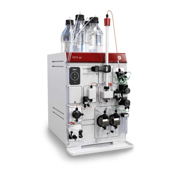
3 System description 3.1 ÄKTA go ÄKTA go Introduction This section gives an overview of the ÄKTA go instrument. Illustration of the ÄKTA go system The illustration below shows the ÄKTA go system. The computer with the UNICORN software is located on the right hand side of the instrument to make room for accessories on the left hand side of the instrument. - Page 19 3 System description 3.1 ÄKTA go Illustration of the ÄKTA go instrument The illustration below shows the ÄKTA go instrument after installation. Part Function Pump Pump rinsing solution tube Pressure monitor Mixer Ready Injection valve UV monitor Top tray Holder rails Instrument control panel Conductivity monitor Flow restrictor...
- Page 20 3 System description 3.1 ÄKTA go Illustration Part Function Display Status indicator Pause button Run/Continue button On/Off button Status indicators The display and status indicators on the instrument control panel indicate the current status of ÄKTA go. The table below describes the different states that can be displayed. State Display Description...
- Page 21 3 System description 3.1 ÄKTA go State Display Description Turning on/off The On/Off button is pressed and the instrument is turning on or off. Offline Power is on, but the instrument has no communication with the UNICORN instrument server. The display toggles between Offline, the instrument IP address, and the Instrument serial number.
- Page 22 3 System description 3.1 ÄKTA go State Display Description A run is ongoing. Pause A run has been paused (pump is stopped). Hold A run has been put on hold (pump is still pumping at an unchanged flow rate). Wash A system wash or a pump wash instruction is ongoing.
- Page 23 3 System description 3.1 ÄKTA go State Display Description Power-save The instrument is in power-saving mode. The status indicator is half-lit with a white light, flashing slowly. Re-program- A module is being ming re-programmed during an instrument configuration installation. ÄKTA go Operating Instructions 29360951 AC...
-
Page 24: Available Modules
3 System description 3.2 Available modules Available modules Introduction The ÄKTA go instrument is delivered with standard modules installed. Six additional modules can be installed in the system, two inside the chassis and four connected via cables at the rear of the instrument. This section describes the standard and optional modules. - Page 25 3 System description 3.2 Available modules Optional modules The following modules can be added to the system. A maximum of six optional modules can be connected to the system. Module Description External air sensor L9- An air sensor used to either complete sample loading via the pump, or to detect if the system has run out of buffer, depending on placement.
- Page 26 3.2 Available modules Real-Time Unit The system can be equipped with a Real-Time Unit, which must be installed by a GE Healthcare service representative. The Real-Time Unit can be used in certain network environments to make sure the run continues if the computer is rebooted or otherwise locked due to, for example, software updates.
-
Page 27: Unicorn
Advanced features requires Evaluation Classic, available from GE Healthcare. When working with the software modules Administration, Method Editor, System Control, and Evaluation it is possible to access descriptions of the active window or software instruction by pressing the F1 key. - Page 28 3 System description 3.3 UNICORN Opening a UNICORN module Modules to open are selected at log in, but can also be opened from another module when the software is already open. In the Administration, Method Editor, or System Control modules, to open a software module, click Tools and select the desired module. When in the Evaluation module, to open a software module, click File:Applications and select the desired module.
- Page 29 This button opens the Con- umn Handling tool, which nect to Systems dialog box contains a column list, with where systems can be con- parameters for GE nected, and currently con- Healthcare columns. With nected users are displayed. an additional license, a Col-...
- Page 30 3 System description 3.3 UNICORN Process Picture pane The most commonly used manual interactions can be done using the Process Picture. Click on the different parts of the Process Picture pane to interact with the system. For a complete list of manual instructions, go to Manual: Execute manual instructions. ÄKTA go Operating Instructions 29360951 AC...
-
Page 31: Installation
4 Installation Installation About this chapter This chapter contains information on how to prepare for, and perform an installation of ÄKTA go. In this chapter This chapter contains the following sections: Section See page 4.1 Site preparation 4.2 Hardware installation 4.3 Software installation 4.4 Start UNICORN and connect to system ÄKTA go Operating Instructions 29360951 AC... -
Page 32: Site Preparation
4 Installation 4.1 Site preparation Site preparation Introduction This section describes the site planning and the preparations necessary for the installation of ÄKTA go. The performance specifications of the system can be met only if the laboratory environ- ment fulfills the requirements stated in this chapter. In this section Section See page... -
Page 33: Delivery, Storage, And Unpacking
When you receive the delivery • Record on the receiving documents if there is any apparent damage on the delivery box. Inform your GE Healthcare representative of such damage. • Move the delivery box to a protected location indoors. Storage requirements The delivery box should be stored in a protected place indoors. - Page 34 4 Installation 4.1 Site preparation 4.1.1 Delivery, storage, and unpacking Moving the ÄKTA go instrument The instrument is heavier at the front. Do not tip the instrument when lifting. The illustra- tion below shows the recommended way to lift the ÄKTA go instrument. ÄKTA go Operating Instructions 29360951 AC...
-
Page 35: Space Requirements
4 Installation 4.1 Site preparation 4.1.2 Space requirements 4.1.2 Space requirements Introduction This section describes the requirements for the laboratory bench on which the ÄKTA go is placed. WARNING Access to power plug. Do not block access to the power outlet and power plug. - Page 36 4 Installation 4.1 Site preparation 4.1.2 Space requirements Size and weight Parameter Value W (width) 335 mm H (height) 482 mm D (depth) 464 mm Weight 27 kg Allowed weight of buffer bottles on the 10 kg top tray ÄKTA go Operating Instructions 29360951 AC...
-
Page 37: Site Environment
4 Installation 4.1 Site preparation 4.1.3 Site environment 4.1.3 Site environment Introduction This section describes the environmental requirements for installation of ÄKTA go. Environmental requirements The following general requirements must be fulfilled: • The room must have exhaust ventilation. • The instrument must not be exposed to direct sunlight. - Page 38 4 Installation 4.1 Site preparation 4.1.3 Site environment Heat output The heat output is listed in the table below. Component Heat output ÄKTA go instrument Typical 100 W Max 150 W Power save < 20 W For heat output of the computer, refer to the manufacturer's specifications. ÄKTA go Operating Instructions 29360951 AC...
-
Page 39: Power Requirements
WARNING Power cord. Only use power cords with approved plugs delivered or approved by GE Healthcare. The following table specifies the power requirements for the ÄKTA go instrument. For power requirements for the computer, refer to the manufacturer's specifications. -
Page 40: Computer Requirements
ÄKTA go instruments are controlled by UNICORN software running on an external com- puter. The computer is not included with the ÄKTA go instrument. A suitable computer may be ordered from GE Healthcare or obtained from a third party supplier. -
Page 41: Required Materials
4 Installation 4.1 Site preparation 4.1.6 Required materials 4.1.6 Required materials Introduction This section describes the materials required for the installation and operation of the ÄKTA go instrument. Solutions The solutions listed in the following table are required during the installation procedure and should be provided at the installation site. -
Page 42: Hardware Installation
4 Installation 4.2 Hardware installation Hardware installation Introduction This section describes the installation procedures for ÄKTA go. In this section This section contains the following subsections: Section See page 4.2.1 Connect the system 4.2.2 Install waste tubing 4.2.3 Prepare the pump rinsing system 4.2.4 Start the instrument ÄKTA go Operating Instructions 29360951 AC... -
Page 43: Connect The System
WARNING Power cord. Only use power cords with approved plugs delivered or approved by GE Healthcare. WARNING Supply voltage. Before connecting the power cord, make sure that the supply voltage at the wall outlet corresponds to the marking on the instrument. - Page 44 4 Installation 4.2 Hardware installation 4.2.1 Connect the system Connector illustration The illustration below shows where the connectors are located on the ÄKTA go instrument. For connectors on the computer equipment, refer to the manufacturer´s documentation. Connect to power Follow the steps below to connect power to the ÄKTA go instrument and the computer. Step Action Select the correct power cord to be used.
- Page 45 4 Installation 4.2 Hardware installation 4.2.1 Connect the system Connect ÄKTA go to the computer Follow the steps below to connect the ÄKTA go to the computer. Step Action Connect a network cable to the back of the instrument. The appropriate port at the back of the instrument is indicated by this symbol: Connect the other end of the network cable to the appropriate connector on the computer.
-
Page 46: Install Waste Tubing
4 Installation 4.2 Hardware installation 4.2.2 Install waste tubing 4.2.2 Install waste tubing Introduction The table below lists the waste tubing of the instrument and where it is located. Make sure that the waste tubing is connected to the correct positions on the modules. Module Tubing connections Location of tubing... - Page 47 4 Installation 4.2 Hardware installation 4.2.2 Install waste tubing Step Action Insert the waste tubing from all installed modules in a suitable vessel. Cut the waste tubing to appropriate length. It is important that the tubing is not bent. Note: If the tubing is too short, replace it with new tubing.
-
Page 48: Prepare The Pump Rinsing System
4 Installation 4.2 Hardware installation 4.2.3 Prepare the pump rinsing system 4.2.3 Prepare the pump rinsing system Introduction The pump rinsing system protects the pump seals from damage caused by precipitated buffer remaining in the system. The seal prevents leakage between the pump chamber and the drive mechanism of the pump. - Page 49 4 Installation 4.2 Hardware installation 4.2.3 Prepare the pump rinsing system Prime the pump rinsing system Follow the instructions below to fill the pump rinsing system with rinsing solution. Step Action Unscrew and remove the rinsing solution tube from the holder. Fill the rinsing solution tube with 50 mL of 20% ethanol or aqueous buffer.
- Page 50 4 Installation 4.2 Hardware installation 4.2.3 Prepare the pump rinsing system Step Action Disconnect the syringe and discard its contents. Insert the outlet tubing into the liquid in the rinsing solution tube. Unscrew the rinsing solution tube and fill it with 50 mL of 20% ethanol or aqueous buffer.
-
Page 51: Start The Instrument
4 Installation 4.2 Hardware installation 4.2.4 Start the instrument 4.2.4 Start the instrument Follow the steps below to start the instrument. Step Action Turn on the instrument by pressing the On/Off button for 2 seconds. The instrument control panel displays a white light for approximately 2 seconds. -
Page 52: Software Installation
4 Installation 4.3 Software installation Software installation Introduction This section gives an overview of how to install UNICORN and adapt the software to your instrument. For more information, see the UNICORN Quick Installation Guide. The software should be installed by someone assigned to be a UNICORN system admin- istrator at the site. -
Page 53: Download And Install Unicorn
4 Installation 4.3 Software installation 4.3.1 Download and Install UNICORN 4.3.1 Download and Install UNICORN UNICORN is delivered via e-Delivery. A path to e-Delivery and Activation ID are delivered upon ordering the ÄKTA go system. Follow the steps below to install the UNICORN software. For more information on installing UNICORN, Windows settings, and configuring the e-license, refer to the UNICORN Quick Installation Guide. -
Page 54: Download The Instrument Configuration
4 Installation 4.3 Software installation 4.3.2 Download the Instrument Configuration 4.3.2 Download the Instrument Configuration An instrument configuration is used to adapt UNICORN to your instrument. Follow the instructions below to import the Instrument Configuration into the UNICORN software. Step Action Go to www.gelifesciences.com/aktago. -
Page 55: Adapt Unicorn To Your System
4 Installation 4.3 Software installation 4.3.3 Adapt UNICORN to your system 4.3.3 Adapt UNICORN to your system To be able to connect to the system, UNICORN must be adapted to the instrument with the correct instrument configuration installed and the correct modules selected in the software. - Page 56 4 Installation 4.3 Software installation 4.3.3 Adapt UNICORN to your system Note: A detailed description of how to adapt UNICORN to your system, including system setup, is found in the UNICORN Administration and Technical Manual. ÄKTA go Operating Instructions 29360951 AC...
-
Page 57: Start Unicorn And Connect To System
4 Installation 4.4 Start UNICORN and connect to system Start UNICORN and connect to system Introduction This section describes how to start and log on to UNICORN, and how to connect to the system in UNICORN. Prerequisites For UNICORN to be correctly installed, the following conditions must be set: •... - Page 58 4 Installation 4.4 Start UNICORN and connect to system Connect to system Follow the instructions to connect to the system in UNICORN. Note: The system must have been defined by the UNICORN system administrator for it to be present in the database. Step Action In the System Control module, click the Connect to Systems button.
- Page 59 4 Installation 4.4 Start UNICORN and connect to system Set up Power-save To minimize power consumption when the system is not used, there is a Power-save function in UNICORN. Follow the steps below to activate the Power-save function. Step Action In System Control click System:Settings:Advanced.
-
Page 60: Prepare The System For A Run
5 Prepare the system for a run Prepare the system for a run About this chapter This chapter gives instructions on how to prepare the ÄKTA go system for a run and what to do before the first run. Safety precautions WARNING Explosion hazard. -
Page 61: Prepare The Flow Paths
5 Prepare the system for a run 5.1 Prepare the flow paths Prepare the flow paths Introduction The ÄKTA go instrument, as delivered, is prepared with a default flow path. The modules in this flow path must be defined in the software, see Section 4.3.3 Adapt UNICORN to your system, on page 55. - Page 62 5 Prepare the system for a run 5.1 Prepare the flow paths Illustration of the flow path The illustration below shows the flow path for a standard configured ÄKTA go instrument with an optional fraction collector connected. The individual instrument modules are presented in the table below.
- Page 63 5 Prepare the system for a run 5.1 Prepare the flow paths Prepare the waste tubing CAUTION Fasten the waste tubing. Make sure that tubing is securely fas- tened to the waste ports W, W1, and W2. Make sure that the waste tubing is prepared according to the instructions in Section 4.2.2 Install waste tubing, on page Prepare the outlet tubing...
-
Page 64: Prime Inlets And Purge Pump Heads
5 Prepare the system for a run 5.2 Prime inlets and purge pump heads Prime inlets and purge pump heads Introduction Before using the pump, it is important to prime all of the inlets and purge the pump heads, that is, to fill the inlets and pump heads with liquid so that no air remains inside. Overview The procedure consists of the following stages: 1 Prime the inlet tubing... - Page 65 5 Prepare the system for a run 5.2 Prime inlets and purge pump heads Step Action Connect a 25 to 30 mL syringe to the purge valve of one of the pump heads. Open the purge valve by turning it counter-clockwise one and a half turns. Draw liquid slowly into the syringe until liquid reaches the pump and the inlet tubing is filled with liquid.
- Page 66 5 Prepare the system for a run 5.2 Prime inlets and purge pump heads Purge the pump and confirm it is free from air Follow the steps below to purge the two pump heads of the pump so that they are free from air.
- Page 67 5 Prepare the system for a run 5.2 Prime inlets and purge pump heads Step Action Under Flow, enter 5 mL/min and click Set. Result: A system flow starts. Connect a 25 to 30 mL syringe to the purge valve of the left pump head. Open the purge valve by turning it counter-clockwise about one and a half turns.
- Page 68 5 Prepare the system for a run 5.2 Prime inlets and purge pump heads Step Action Keep the system flow running. Connect the syringe to the purge valve of the right pump head, and repeat steps 5 and 6. In the Chromatogram pane, check the pressure curve. If the pressure does not stabilize within a few minutes, there could be air left in the pump.
- Page 69 5 Prepare the system for a run 5.2 Prime inlets and purge pump heads Step Action Unstable pressure (air in the Pump) If the pressure does not stabilize within a few minutes, repeat the procedures to prime the inlet tubing and purge the pump. If the pressure still does not stabilize, see the ÄKTA go User Manual for further instructions.
-
Page 70: Performance Tests
5 Prepare the system for a run 5.3 Performance tests Performance tests Introduction This section describes how to run performance tests. Performance tests should be run before taking ÄKTA go into use, to check the functionality of the equipment. After instal- lation of a standard equipped ÄKTA go instrument, the System test and Mixer test must be run. - Page 71 5 Prepare the system for a run 5.3 Performance tests Step Action In the System Performance Test tab, in the list Available performance methods, select the test you want to run. Method notes for the selected test are shown in the right side panel. Note: This dialog lists all tests that are available for the modules that can be installed in the ÄKTA go system.
- Page 72 5 Prepare the system for a run 5.3 Performance tests Step Action Tick the checkboxes Save to file System test and Print report System test. Click Next > to continue. Note: A printer must be installed on the UNICORN Instrument Server to be able to print the report (see the UNICORN Administration and Technical Manual for details).
- Page 73 Follow any instructions that are shown on the screen. Check whether the test was passed or failed in the System Performance Report, which is located at C:\Program Files (x86)\GE Healthcare\UNI- CORN\UNICORN x.x\Temp, where x.x is the UNICORN version number. The test result is stated at the top of the report.
-
Page 74: Connect A Column
5 Prepare the system for a run 5.4 Connect a column Connect a column Introduction This section describes how to connect a column to the instrument, without introducing air into the flow path. Use a column holder to secure the column. Several types of column holders are available for ÄKTA go. - Page 75 5 Prepare the system for a run 5.4 Connect a column Attach a column holder and connect a column Follow the instructions below to connect a column to the instrument. Note: If the column is filled with 20% ethanol, do not use a salt-containing liquid when connecting it to the flow path because salt might precipitate in 20% ethanol.
- Page 76 5 Prepare the system for a run 5.4 Connect a column Step Action When buffer is dripping from tubing prepared in step 3, fill the top part of the column with buffer by letting it drip from the tube. When it is filled, con- nect the tubing drop-to-drop to the top of the column.
-
Page 77: Pressure Alarms
5 Prepare the system for a run 5.5 Pressure alarms Pressure alarms Introduction The ÄKTA go instrument is equipped with a pressure monitor directly after the pump, which measures the highest pressure in the instrument. The advanced column valve, V9-C, adds two extra pressure sensors, one directly before the column and one directly after the column. -
Page 78: Prepare For A Run At Low Temperature
5 Prepare the system for a run 5.6 Prepare for a run at low temperature Prepare for a run at low temperature Introduction The viscosity of the liquids increase as the temperature decreases. Therefore, when using the instrument in a cold room or cold cabinet, decrease the flow rate and follow the precautions listed below. -
Page 79: Run A Method
6 Run a method Run a method About this chapter This chapter gives instructions on how to run your method. In this chapter Section See page 6.1 Create a method 6.2 Prepare sample for loading 6.3 Start a method run 6.4 Monitor or interact with the run 6.5 Evaluate the run 6.6 Procedures after the run... -
Page 80: Create A Method
6 Run a method 6.1 Create a method Create a method Create a new method using the Method Editor Follow the steps below to create a method using a predefined method template. The example given uses an Affinity Chromatography method from UNICORN 7.4. The Method Settings phase sets up parameters that are used throughout the method, such as unit for method base and flow rate. - Page 81 6 Run a method 6.1 Create a method Step Action In the Sample Application phase, choose an appropriate sample application technique and volume. See Section 6.2 Prepare sample for loading, on page 82 for suitable sample application techniques for your sample volume. Tip: If you are using a sample loop, empty the loop with 3 to 5 volumes of buffer.
-
Page 82: Prepare Sample For Loading
6 Run a method 6.2 Prepare sample for loading Prepare sample for loading Introduction This section describes how to prepare the sample for loading onto the column. This can be done using either a sample loop, a Superloop, or the pump. When using the pump to apply the sample, the sample inlet must first be primed. - Page 83 6 Run a method 6.2 Prepare sample for loading Prepare sample for application using the pump Follow the steps below to prepare for sample application using the pump. Step Action Make sure that the sample inlet tubing that is to be used during the run is placed in the sample container.
-
Page 84: Start A Method Run
6 Run a method 6.3 Start a method run Start a method run Prerequisites Make sure that the system is correctly prepared. Confirm the following: • The sample inlet is primed or the sample loop is loaded. • The column is properly connected. •... -
Page 85: Monitor Or Interact With The Run
6 Run a method 6.4 Monitor or interact with the run Monitor or interact with the run Monitor or interact with the run using the System Control module You can follow your ongoing method run in the System Control module. If you need to interrupt your run, use the Hold, Pause, or End buttons in the System Control toolbar. -
Page 86: Evaluate The Run
6 Run a method 6.5 Evaluate the run Evaluate the run Introduction After the run is completed, the results can be evaluated using the Evaluation module. To open the results, use the following steps. For more information on evaluating results, refer to the UNICORN user documentation. -
Page 87: Procedures After The Run
6 Run a method 6.6 Procedures after the run Procedures after the run Introduction After the run, the instrument and column should be cleaned to prevent bacterial growth, sample contamination in the next run, and column clogging. This section describes how to clean the column using a Column CIP (Cleaning-In-Place) method, prepare the column and the instrument for storage, and how to shut down the system. - Page 88 6 Run a method 6.6 Procedures after the run Column storage If the column is not going to be used for a couple of days or longer, it must be placed in a storage solution (20% ethanol) after a Column CIP run. Refer to the instructions for your column for specific storage instructions.
- Page 89 6 Run a method 6.6 Procedures after the run Note: If you have a column valve, make sure all positions are put in storage solution. Shut down the system Follow the steps below to shut down the system. Step Action Select Exit UNICORN from the File menu in any module in the UNICORN software.
-
Page 90: Maintenance
For a complete list of maintenance procedures, see the ÄKTA go User Manual. WARNING All maintenance procedures inside the instrument chassis must be performed by a GE Healthcare service representative. In this chapter Section See page 7.1 Clean the instrument externally... -
Page 91: Clean The Instrument Externally
7 Maintenance 7.1 Clean the instrument externally Clean the instrument externally CAUTION Disconnect the power cord form the power outlet before cleaning the instrument. Maintenance interval Clean the instrument externally when required. Do not allow spilled liquid to dry on the instrument. -
Page 92: Perform System Cleaning-In-Place (Cip)
7 Maintenance 7.2 Perform system Cleaning-In-Place (CIP) Perform system Cleaning-In-Place (CIP) Maintenance interval Perform a system CIP using when required, for example between runs where different samples are used. This is important to prevent cross-contamination and bacterial growth in the instrument. Required material The following materials are required: •... - Page 93 7 Maintenance 7.2 Perform system Cleaning-In-Place (CIP) CAUTION Explosion hazard if flammable liquid leaks during cleaning of the flow path. When cleaning the flow path of ÄKTA go with a flammable liquid like ethanol, carefully inspect the flow path, includ- ing the waste tubing, to make sure there will be no leakage.
- Page 94 7 Maintenance 7.2 Perform system Cleaning-In-Place (CIP) Step Action Click the Save button. In the Save As dialog, select a target folder, enter the Name for the method, select a System from the list, and click Save. Perform a System CIP Follow the steps below to run a System CIP method.
- Page 95 7 Maintenance 7.2 Perform system Cleaning-In-Place (CIP) Step Action Connect a suitable sample loop to the injection valve ports LoopF (fill) and LoopE (empty). Note: Do not use a Superloop when cleaning the Injection valve. Make sure there is waste tubing to the injection valve port W2 and W1 and that they are secured in a waste container.
-
Page 96: Replace Pump Rinsing Liquid
7 Maintenance 7.3 Replace pump rinsing liquid Replace pump rinsing liquid Replace pump rinsing liquid once a week if you are using 20% ethanol and daily if you are using an aqueous buffer. For instructions, see Section 4.2.3 Prepare the pump rinsing system, on page ÄKTA go Operating Instructions 29360951 AC... -
Page 97: Replace The Main Fuses
7 Maintenance 7.4 Replace the main fuses Replace the main fuses WARNING Disconnect power. Always disconnect power from the instrument before replacing fuses. WARNING For continued protection from fire hazard, replace only with same type and rating of fuse. WARNING If a fuse requires repeated replacement, do not continue to use the instrument. - Page 98 7 Maintenance 7.4 Replace the main fuses Step Action Use a small flat-bladed screwdriver to prise open the fuse holder cover on the power inlet. Pull the fuse holder out of the mains connector panel by hand. Remove the fuses from the fuse holder. Fit new fuses of the same size and rating Replace the fuse holder in the power inlet.
-
Page 99: Troubleshooting
8 Troubleshooting Troubleshooting About this chapter This chapter provides a list of the most commonly encountered problems that might occur when operating ÄKTA go. For a more comprehensive list and a more detailed de- scription of the actions to take, refer to the ÄKTA go User Manual. Problem Possible cause Corrective action... - Page 100 System error report When you request troubleshooting assistance from GE Healthcare, you should generate a System error report and submit it to your service representative. Follow the instructions below to generate a System error report.
-
Page 101: Reference Information
9 Reference information Reference information About this chapter This chapter contains reference information. In this chapter Section See page 9.1 System specifications 9.2 Chemical resistance specifications 9.3 Recycling information 9.4 Regulatory information 9.5 Health and Safety Declaration Forms ÄKTA go Operating Instructions 29360951 AC... -
Page 102: System Specifications
9 Reference information 9.1 System specifications System specifications Technical specifications Parameter Data System configuration Benchtop system, external computer Flow rate range 0.01 to 25 mL/min Pressure range 0 to 5 MPa (0 to 50 bar) Control system UNICORN 7.4 or later version Connection between PC and instrument Ethernet Dimensions (width ×... -
Page 103: Chemical Resistance Specifications
Introduction This section provides detailed information about chemical resistance of the ÄKTA go in- strument to some common aggressive chemicals used in liquid chromatography. For information regarding chemicals not listed in this section, contact your GE Healthcare representative. Note: Refer to Safety Data Sheets (SDS) for information regarding characteristics, human and environmental risks and preventive measures for chemicals used. - Page 104 9 Reference information 9.2 Chemical resistance specifications Chemical Concentration CAS no EC no Ethylene glycol 107-21-1 203-473-3 Ethylenediaminetetraacetic acid 100 mM 60-00-4 200-449-4 (EDTA) Glycerol 56-81-5 200-289-5 Guanidinium hydrochloride 50-01-1 200-002-3 Mercaptoethanol 20 mM 37482-11-4 253-523-3 Phosphoric acid 0.1 M 7664-38-2 231-633-2 Potassium chloride...
- Page 105 9 Reference information 9.2 Chemical resistance specifications Chemical Concentration CAS no EC no Sodium hypochlorite 7681-52-9 231-668-3 Hydrochloric acid concentration should not exceed 0.1 M in pressure sensors, for example, in the pressure monitor, or in the column valve V9-C. For other parts of the system up to 1 M HCl is acceptable for short periods of use.
-
Page 106: Recycling Information
When taking the product out of service, the different materials must be separated and recycled according to national and local environmental regulations. Recycling of hazardous substances The product contains hazardous substances. Detailed information is available from your GE Healthcare representative. ÄKTA go Operating Instructions 29360951 AC... - Page 107 9 Reference information 9.3 Recycling information Disposal of electrical components Waste electrical and electronic equipment must not be disposed of as unsorted municipal waste and must be collected separately. Contact an authorized representative of the manufacturer for information concerning the decommissioning of the equipment. Disposal of batteries Waste batteries must not be disposed of as unsorted municipal waste and must be collected separately.
-
Page 108: Regulatory Information
This section lists regulatory information that applies to the ÄKTA go system. Manufacturing information The table below summarizes the required manufacturing information. Requirement Information Name and address of manufacturer GE Healthcare Bio-Sciences AB Björkgatan 30 SE 751 84 Uppsala Sweden Telephone number of manufacturer + 46 771 400 600... -
Page 109: European Union And European Economic Area
9 Reference information 9.4 Regulatory information 9.4.1 European Union and European Economic Area 9.4.1 European Union and European Economic Area Introduction This section describes regulatory information for the European Union and European Economic Area that applies to the ÄKTA go system. Conformity with EU Directives See the EU Declaration of Conformity for the directives and regulations that apply for the CE marking. -
Page 110: Eurasian Customs Union
Importer and/or company for obtain- GE Healthcare LLC ing information about importer GE Healthcare Life Sciences Presnenskaya nab., 10C, 12th floor RU-123 317 Moscow, Russian Federation Telephone 1: + 7 495 411 9714 Fax nr: + 7 495 739 6932 Email: LSrus@ge.com... -
Page 111: Regulatory Statements
The user is cautioned that any changes or modifications not expressly approved by GE Healthcare could void the user’s authority to operate the equipment. This equipment has been tested and found to comply with the limits for a Class A digital device, pursuant to part 15 of the FCC Rules. - Page 112 9 Reference information 9.4 Regulatory information 9.4.3 Regulatory statements EMC Statement Korea NOTICE Class A equipment (equipment for business use). This equipment has been evaluated for its suitability for use in a business environment. When used in a residential environment, there is a concern of radio interference.
-
Page 113: Declaration Of Hazardous Substances (Dohs)
9 Reference information 9.4 Regulatory information 9.4.4 Declaration of Hazardous Substances (DoHS) 9.4.4 Declaration of Hazardous Substances (DoHS) 根据SJ/T11364-2014《电子电气产品有害物质限制使用标识要求》特提供如下有关污染控制方面的 信息。 The following product pollution control information is provided according to SJ/T11364-2014 Marking for Restriction of Hazardous Substances caused by electrical and electronic products. 电子信息产品污染控制标志说明... - Page 114 9 Reference information 9.4 Regulatory information 9.4.4 Declaration of Hazardous Substances (DoHS) 有害物质的名称及含量 Name and Concentration of Hazardous Substances 产品中有害物质的名称及含量 Table of Hazardous Substances’ Name and Concentration 部件名称 有害物质 Component name Hazardous substance 铅 汞 镉 六价铬 多溴联苯 多溴二苯醚 (Pb) (Hg) (Cd) (Cr(VI))
-
Page 115: Health And Safety Declaration Forms
Service Ticket #: To make the mutual protection and safety of GE service personnel and our customers, all equipment and work areas must be clean and free of any hazardous contaminants before a Service Engineer starts a repair. To avoid delays in the servicing of your equipment, please complete this checklist and present it to the Service Engineer upon arrival. - Page 116 To make sure the mutual protection and safety of GE personnel, our customers, transportation personnel and our environment, all equipment must be clean and free of any hazardous contaminants before shipping to GE. To avoid delays in the processing of your equipment, please complete this checklist and include it with your return.
- Page 117 All goods and services are sold subject to the terms and conditions of sale of Sweden the company within GE Healthcare which supplies them. A copy of these terms and conditions is available on request. Contact your local GE Healthcare repre- www.gelifesciences.com/aktago...
Need help?
Do you have a question about the AKTA GO and is the answer not in the manual?
Questions and answers