
Related Manuals for GE AKTAprime plus


Summary of Contents for GE AKTAprime plus
- Page 1 GE Healthcare Life Sciences ÄKTAprime™ plus Operating Instructions Original instructions...
-
Page 3: Table Of Contents
Table of Contents Table of Contents Introduction ......................Important user information ......................Regulatory information ........................Instrument ............................... Monitoring and evaluation ....................... User documentation ........................... Safety instructions ....................Safety precautions ..........................Labels ................................. Emergency procedures ........................Recycling information ......................... Declaration of Hazardous Substances (DoHS) ................ Installation ...................... - Page 4 Table of Contents Reference information ..................Specifications ............................Chemical resistance ..........................System recommendations ....................... Health and Safety Declaration Form ................... Ordering information .......................... Connection diagram - Liquid flow path ............Tubing ........................ÄKTAprime plus Operating Instructions 28-9597-89 AB...
-
Page 5: Introduction
1 Introduction Introduction Purpose of the Operating Instructions The Operating Instructions provide you with the instructions needed to handle ÄKTAprime plus in a safe way. Prerequisites In order to operate ÄKTAprime plus as is intended, the following pre-requisites must be fulfilled: •... -
Page 6: Important User Information
1 Introduction 1.1 Important user information Important user information Read this before operating ÄKTAprime plus All users must read the entire Operating Instructions before installing, operating or maintaining ÄKTAprime plus. Always keep the Operating Instructions at hand when operating ÄKTAprime plus. Do not operate ÄKTAprime plus in any other way than described in the user documenta- tion. -
Page 7: Regulatory Information
1 Introduction 1.1 Important user information Cautions CAUTION CAUTION indicates a hazardous situation which, if not avoided, could result in minor or moderate injury. It is important not to proceed until all stated conditions are met and clearly understood. Notices NOTICE NOTICE indicates instructions that must be followed to avoid damage to the product or other equipment. - Page 8 CE marked instruments, or • connected to other products recommended or described in the user documentation, • used in the same state as it was delivered from GE Healthcare, except for alterations described in the user documentation. ÄKTAprime plus Operating Instructions 28-9597-89 AB...
- Page 9 1 Introduction 1.2 Regulatory information International standards This product fulfills the requirements of the following standards: Standard Description Notes EN/IEC 61010-1, Safety requirements for electrical EN standard is harmonized UL 61010-1, equipment for measurement, with EU directive CAN/CSA-C22.2 control, and laboratory use 2006/95/EC No.
-
Page 10: Instrument
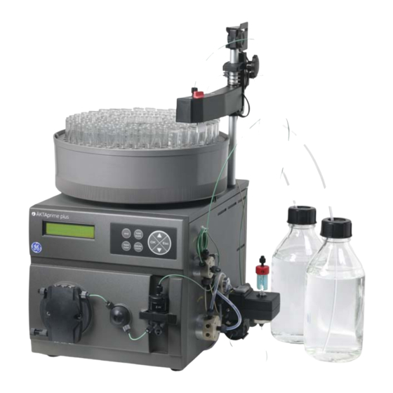
1 Introduction 1.3 Instrument Instrument Product description ÄKTAprime plus is a compact liquid chromatography system designed for one-step pu- rification of proteins at laboratory scale. Figure 1.1: The main parts of the instrument. Part Function Part Function Fraction collector Switch valve Monitor and controller Conductivity cell LCD display... - Page 11 1 Introduction 1.3 Instrument The Power switch is located at the rear of the system. Electrical and communication connections pH-Probe pH-Ground Drop Sensor Frac Valve Recorder Conductivity Flow Cell RS-232 Rec. On/off Mains UV-lamp Voltage Frequency Power max 100-120 / 220-240 V autorange 50-60 Hz...
- Page 12 1 Introduction 1.3 Instrument Navigation menu The system is operated from the push buttons and LCD display at the front panel. hold /cont feed pause tube /cont Figure 1.2: Push buttons. Button Description Find a specific menu option Enter a menu. Return one menu level.
-
Page 13: Monitoring And Evaluation
1 Introduction 1.3 Instrument Basic flow path Figure 1.3: Basic flow path. Stage Part Description P, V1 Pump P pumps buffer from a buffer container connected to the buffer valve V1. SW, B To form a gradient the switch valve (SW) can be used to pull liquid from buffer container (B). -
Page 14: User Documentation
1 Introduction 1.4 Monitoring and evaluation Paper chart recorder It is possible to connect a chart recorder to ÄKTAprime plus to get real time monitoring. For more information see the ÄKTAprime plus User Manual. User documentation In addition to these Operating Instructions, the documentation package supplied with ÄKTAprime plus also includes product documentation binders containing detailed specifications and traceability documents. - Page 15 A complete control software package for supervision of ÄKTAprime plus automated liquid chromatogra- phy systems. Component documentation Documentation for components produced both by GE Healthcare and by a third-party are, if existent, also included in the document package. ÄKTAprime plus Operating Instructions 28-9597-89 AB...
-
Page 16: Safety Instructions
2 Safety instructions Safety instructions About this chapter This chapter describes safety compliance, safety labels, general safety precautions, emergency procedures, power failure and recycling of ÄKTAprime plus. Safety precautions Introduction The ÄKTAprime plus instrument is powered by mains voltage and handles pressurized liquids that may be hazardous. - Page 17 WARNING Do not use any accessories not supplied or recommended by GE Healthcare. WARNING Do not use ÄKTAprime plus if it is not working properly, or if it has suffered any damage, for example: •...
- Page 18 2 Safety instructions 2.1 Safety precautions NOTICE Avoid condensation by letting the unit equilibrate to ambient tem- perature. Using flammable liquids When using flammable liquids with the ÄKTAprime plus instrument, follow these precau- tions to avoid any risk of fire or explosion. WARNING Fire Hazard.
- Page 19 WARNING Protective ground. ÄKTAprime plus must always be connected to a grounded power outlet. WARNING Power cord. Only use power cords with approved plugs delivered or approved by GE Healthcare. ÄKTAprime plus Operating Instructions 28-9597-89 AB...
- Page 20 2 Safety instructions 2.1 Safety precautions WARNING Access to power switch and power cord with plug. Do not block access to the power switch and power cord. The power switch must always be easy to access. The power cord with plug must always be easy to disconnect.
- Page 21 2 Safety instructions 2.1 Safety precautions WARNING Hazardous biological agents during run. When using hazardous biological agents, run System CIP and Column CIP to flush the entire system tubing with bacteriostatic solution (e.g. NaOH) fol- lowed by a neutral buffer and finally distilled water, before service and maintenance.
- Page 22 2.1 Safety precautions Maintenance WARNING Electrical shock hazard. All repairs should be done by service personnel authorized by GE Healthcare. Do not open any covers or replace parts unless specifically stated in the user documenta- tion. WARNING Disconnect power. Always disconnect power from the instrument before replacing any component on the instrument, unless stated otherwise in the user documentation.
- Page 23 2 Safety instructions 2.1 Safety precautions WARNING NaOH is corrosive and therefore dangerous to health. When using hazardous chemicals, avoid spillage and wear protective glasses and other suitable Personal Protective Equipment (PPE). WARNING After assembly, the piping system must be tested for leakage at maximum pressure for continued protection against injury risks due to fluid jets, burst pipes or explosive atmosphere.
-
Page 24: Labels
2 Safety instructions 2.1 Safety precautions CAUTION The system uses high intensity ultra-violet light. Do not remove the UV lamp while the system is running. Before replacing a UV lamp, ensure that the lamp is disconnected to prevent injury to eyes. If the mercury lamp is broken, make sure that all mercury is re- moved and disposed according to national and local environmental regulations. - Page 25 2 Safety instructions 2.2 Labels Symbols used in instrument labels Label Meaning Warning! Read the user documentation before using the system. Do not open any covers or replace parts unless specifically stated in the user documentation. The system complies with the requirements for electromagnetic compli- ance (EMC) in Australia and New Zealand.
-
Page 26: Emergency Procedures
2 Safety instructions 2.3 Emergency procedures Emergency procedures In this section This section describes how to do an emergency shutdown of the ÄKTAprime plus system. The section also describes the result in the event of power failure. Emergency shutdown In an emergency situation, do as follows to stop the run: Step Action To pause the run without ending the method, press the Pause button located... -
Page 27: Recycling Information
Recycling of hazardous substances ÄKTAprime plus contains hazardous substances. Detailed information is available from your GE Healthcare representative. Disposal of electrical components Waste of electrical and electronic equipment must not be disposed as unsorted municipal waste and must be collected separately. -
Page 28: Declaration Of Hazardous Substances (Dohs)
2 Safety instructions 2.5 Declaration of Hazardous Substances (DoHS) Declaration of Hazardous Substances (DoHS) Introduction The following product pollution control information is provided according to SJ/T11364- 2006 Marking for Control of Pollution caused by Electronic Information Products. 根据SJ/T11364-2006《电子信息产品污染控制标识要求》特提供如下有关污染 控制 方面的信息 Symbols used in pollution control label 电子信息产品污染控制标志说明... - Page 29 2 Safety instructions 2.5 Declaration of Hazardous Substances (DoHS) Label Meaning 该标志表明本产品含有超过SJ/T11363-2006《电子信息产品中有毒 有害物质的限 量要求》中限量的有毒有害物质。标志中的数字为本 产品的环保使用期,表明本 产品在正常使用的条件下,有毒有害物 质不会发生外泄或突变,用户使用本产品 不会对环境造成严重污染 或对其人身、财产造成严重损害的期限。单位为年。 为保证所申明的环保使用期限,应按产品手册中所规定的环境条件 和方法进行正 常使用,并严格遵守产品维修手册中规定的期维修和 保养要求。 产品中的消耗件和某些零部件可能有其单独的环保使用期限标志, 并且其环保使 用期限有可能比整个产品本身的环保使用期限短。应 到期按产品维修程序更换那 些消耗件和零部件,以保证所申明的整 个产品的环保使用期限。 本产品在使用寿命结束时不可作为普通生活垃圾处理,应被单独收 集妥善处理 List of hazardous substances and their concentrations 产品中有毒有害物质或元素的名称及含量 Indication for each major part if substance exceeds limit Value Meaning Indicates that this toxic or hazardous substance contained in all of the...
- Page 30 2 Safety instructions 2.5 Declaration of Hazardous Substances (DoHS) List of hazardous substances Component Hazardous substance name 有毒有害物质或元素 部件名称 Cr6+ PBDE 铅 汞 镉 六价铬 多溴联苯 多溴二苯醚 ÄKTAprime plus The product has not been tested as per the Chinese standard SJ/T11363-2006 Requirements for Concentration Limits for Certain Hazardous Substances in Electronic Information Product.
-
Page 31: Installation
3 Installation Installation ÄKTAprime plus is delivered in protective packing material and shall be unpacked with great care. Any equipment connected to ÄKTAprime plus must fulfill applicable standards and local regulations. A video describing the installation process, is supplied with each ÄKTAprime plus system. For detailed information on Installation, see ÄKTAprime plus User Manual. -
Page 32: Unpacking
All parts are either mounted on the system or located in the accessory kit box. If any damage is found, document the damage, and contact your local GE Healthcare representative. Unpack the system Remove straps and packing material. -
Page 33: Operation
4 Operation Operation About this chapter This chapter provides instructions for the use of ÄKTAprime plus. Operation overview Workflow The typical workflow in ÄKTAprime plus, after turning on the system, can be divided into a number of steps. Step Action Section Prepare the system for a run Section 4.3 Preparations before start, on page 34... -
Page 34: Preparations Before Start
4 Operation 4.2 Starting the instrument 4 The self-test takes about 30–40 seconds. When the test is completed, the display shows the Templates menu. Note: The system can be used for most applications after 15 min of lamp warm-up but the full specifications are not obtained until after 1 hour. Preparations before start Buffer preparation Prepare buffers according to ÄKTAprime plus cue cards. - Page 35 4 Operation 4.3 Preparations before start 6 Choose to wash the A2–A8 inlet tubing that is used by pressing OK at those cursor positions. A1 and B will always be washed. Note: At delivery, only A1 and B are installed. 7 Scroll to OK and press the OK button.
- Page 36 4 Operation 4.3 Preparations before start 2 Press OK. The switch valve turns to the inlet B port. 3 Draw buffer with the purge syringe until liquid enters the syringe. 4 Replace the purge tubing with the stop plug. 5 Stop the pump by pressing end and then OK. Flushing the pump with 100% ethanol: 1 Put inlet tubing A1 in deionized water.
- Page 37 4 Operation 4.3 Preparations before start Description Description Tubing from injection valve HisTrap column 1/16" male connector UV cell Note: Other unions and connectors might be required for other columns. Preparing the fraction collector 1 Fill the fraction collector rack with, for example, 18 mm tubes (minimum 40 pcs.). 2 Adjust the height of the delivery arm using the lock knob (1) so that the bottom of the tube sensor (2) is about 5 mm below the top of the tubes.
- Page 38 4 Operation 4.3 Preparations before start 4 Check that the tube sensor (1) is in the correct position for the tube size. The eluent tubing should be over the center of the collection tube. Use the red sensor control knob (2) to position the tube holder (3). 5 Rotate the rack by hand until the rear half of the tube sensor rests against the first tube.
-
Page 39: Performing A Run
4 Operation 4.3 Preparations before start 1 Connect a sample loop between port 2 and 6 on the injection valve. Make sure that the sample loop is large enough for your sample. 2 Connect a luer female/1/16" male union to port 3. 3 Fill a syringe with five loop volumes of deionized water or binding buffer. - Page 40 4 Operation 4.4 Performing a run Viewing the run When the pump starts running, the progress of the run can be viewed in the two panes in PrimeView. • The Curves pane displays monitor signal values graphically. • The Logbook pane displays all actions (e.g. method start and end, base instructions and method instructions) and unexpected conditions (e.g.
-
Page 41: Procedures After A Run
4 Operation 4.4 Performing a run Ending the run Press OK at the Method Complete prompt. This will cause all valves to return to their default positions. To stop the run on a system before it is finished: 1 Press the end button. 2 Select yes and press OK. - Page 42 4 Operation 4.5 Procedures after a run NOTICE Do not allow particles to enter the UV flow cell as damage to the flow cell might occur. Buffers not containing any salt can be left in the system for a short time after a run, even overnight (not in the pH electrode, see instructions below).
-
Page 43: Maintenance
For maintenance of a specific component, carefully read the component manual and follow the instructions. WARNING Electrical shock hazard. All repairs should be done by service personnel authorized by GE Healthcare. Do not open any covers or replace parts unless specifically stated in the user documenta- tion. WARNING Disconnect power. -
Page 44: User Maintenance Schedule
5 Maintenance 5.1 General WARNING Do not perform any type of maintenance work while the system is powered electrically or when the piping system is pressurized. Note that the piping system can be pressurized even when the system is closed down. WARNING When using hazardous chemical and biological agents, take all suitable protective measures, such as wearing protective glasses... - Page 45 5 Maintenance 5.2 User maintenance schedule Table 5.1: User maintenance schedule Interval Action Instructions/reference Daily Leak inspection Visually inspect the system for leaks. Wash the system flow 1 For cleaning the flow path, see Cleaning-In- path Place, on page 46. 2 For leaving the system for a few days, see Section 5.7 Storage, on page 49.
-
Page 46: Cleaning
5 Maintenance 5.2 User maintenance schedule Interval Action Instructions/reference Yearly Valve inspection Check for external or internal leakage. Replace channel plate and distribution plate yearly or when required. Refer to the relevant valve in- struction sheet. Cleaning Cleaning before planned maintenance/service To ensure the protection and safety of service personnel, all equipment and work areas must be clean and free of any hazardous contaminants before a Service Engineer starts... -
Page 47: Component Maintenance
The operator must carefully read and understand the instructions supplied for each component before disassembly and assembly of the component. When replacing con- sumables, such as tubing and tubing connectors, all neccessary safety precautions must be taken. Contact your local GE Healthcare representative if further information or help is needed. WARNING Disconnect power. -
Page 48: Calibration
5 Maintenance 5.5 Disassembly and assembly of components and consumables WARNING Before disassembly, check that there is no pressure in the piping system. WARNING After assembly, the piping system must be tested for leakage at maximum pressure for continued protection against injury risks due to fluid jets, burst pipes or explosive atmosphere. -
Page 49: Storage
5 Maintenance 5.7 Storage Storage General recommendation For storage, the system must first be cleaned as described in Cleaning-In-Place, on page 46. After cleaning, the system must be filled with 0.01 M NaOH or 20% ethanol solution. Columns and media shall be stored according to their respective instructions. Storage conditions The following conditions shall be maintained while the system is in storage: •... -
Page 50: Troubleshooting
6 Troubleshooting Troubleshooting UV curve problems Error symptom Possible cause Corrective action Ghost peak Dirt or residues in the Clean the system. Make sure air is flow path from previ- removed. ous runs. Air in the eluents. Residue in the column Clean the column according to the from previous runs column instructions. -
Page 51: Conductivity Curve Problems
6 Troubleshooting 6.1 UV curve problems Error symptom Possible cause Corrective action Low sensitivity Aging UV lamp Check the lamp run time according to and replace if necessary. Refer to ÄKTAprime plus User Manual. UV lamp in wrong po- Check that the lamp position and sition the filter position are both set to the wavelength to be used, 280 nm... - Page 52 6 Troubleshooting 6.2 Conductivity curve problems Error symptom Possible cause Corrective action Waves on the gradi- Incorrect pump func- Check that the pump is operating tion and is programmed correctly. Dirty mixing chamber Check that the mixing chamber is free from dirt or particles. Insufficient mixing Change to a larger mixing cham- chamber volume...
-
Page 53: Ph Curve Problems
6 Troubleshooting 6.2 Conductivity curve problems Error symptom Possible cause Corrective action Incorrect or unstable Loose connection of Check that the conductivity flow reading conductivity flow ca- cell cable is connected properly. Incorrect pump and Check that the pump and valves valves function operate correctly. - Page 54 6 Troubleshooting 6.3 pH curve problems Error symptom Possible cause Corrective action Slow pH response or Contaminated elec- Check the electrode glass mem- Calibration impossible trode glass mem- brane. If it is contaminated, clean brane the electrode following the instruc- tions in Monitor pH/C-900 User Manual.
- Page 55 6 Troubleshooting 6.3 pH curve problems Error symptom Possible cause Corrective action Incorrect or unstable Problem with elec- Check that the electrode cable is pH reading trode connected properly. Check that the electrode is correct- ly inserted in the flow cell and, if necessary, hand-tighten the nut.
-
Page 56: Pressure Curve Problems
6 Troubleshooting 6.3 pH curve problems Error symptom Possible cause Corrective action pH values vary with Problem with the Replace the pH electrode. varied back pressure electrode Pressure curve problems Error symptom Possible cause Corrective action Erratic flow, noisy Air bubbles passing Check all connections for leaks. -
Page 57: Reference Information
7 Reference information Reference information About this chapter This chapter contains technical data, regulatory and other information. Specifications Parameter Value Ingression protection Housing: IP20 Flow cells: IP44 Supply voltage 100-120/220-240 V ~, 50 to 60 Hz Power consumption 90 VA Fuse specification T 1.0 AH 250 V Dimensions (H ×... - Page 58 7 Reference information 7.2 Chemical resistance Chemical Exposure Exposure CAS no. EEC no. Comments < 1 day up to 2 months Acetone, 10% Avoid PVDF is affected by long term use. Ammonia, 30% 7664-41-7 231-635-3 Silicone is affected by long-term use. Ammonium chlo- 12125-02-9 235-186-4...
- Page 59 7 Reference information 7.2 Chemical resistance Chemical Exposure Exposure CAS no. EEC no. Comments < 1 day up to 2 months Formic acid, 100% 64-18-6 200-579-1 Silicone not resis- tant. Glycerol, 100% 56-81-5 200-289-5 Guanidinium hy- drochloride Hexane Avoid Silicone not resis- tant.
- Page 60 7 Reference information 7.2 Chemical resistance Chemical Exposure Exposure CAS no. EEC no. Comments < 1 day up to 2 months Sodium bicarbon- Sodium bisulphate Sodium borate Sodium carbonate Sodium chloride 7647-14-5 231-598-3 Sodium hydroxide, Avoid 1310-73-2 215-185-5 PVDF and borosili- cate glass are af- fected by long term use.
-
Page 61: System Recommendations
7 Reference information 7.3 System recommendations System recommendations Refer to ÄKTAprime plus User Manual, or contact your local GE Healthcare representative for the most current information. ÄKTAprime plus Operating Instructions 28-9597-89 AB... -
Page 62: Health And Safety Declaration Form
Service Ticket #: To ensure the mutual protection and safety of GE Healthcare service personnel and our customers, all equipment and work areas must be clean and free of any hazardous contaminants before a Service Engineer starts a repair. To avoid delays in the servicing of your equipment, please complete this checklist and present it to the Service Engineer upon arrival. - Page 63 1. Please note that items will NOT be accepted for servicing or return without this form 2. Equipment which is not sufficiently cleaned prior to return to GE Healthcare may lead to delays in servicing the equipment and could be subject to additional charges 3.
-
Page 64: Ordering Information
7 Reference information 7.5 Ordering information Ordering information For ordering information visit www.gelifesciences.com/AKTA. ÄKTAprime plus Operating Instructions 28-9597-89 AB... -
Page 65: A Connection Diagram - Liquid Flow Path
A Connection diagram - Liquid flow path Appendix A Connection diagram - Liquid flow path Flow path and components Cond 1100 1000 1250 1250 1000 Description Description Buffers Loop (500 μl) Buffer valve Waste Gradient switch valve Column System pump Male/Male Pressure monitor Flow restrictor (0.2 MPa) -
Page 66: Tubing
B Tubing Appendix B Tubing Names in the Label column in Table B.1 refer to tubing labels in the liquid flow path connection diagram, see Appendix A Connection diagram - Liquid flow path, on page 65. Table B.1: Tubing specifications for ÄKTAprime plus Label Material Length... - Page 68 All goods and services are sold subject to the terms and conditions of sale of the company within GE Healthcare which supplies them. A copy of these terms and conditions is available on request. Contact your local GE Healthcare repre- sentative for the most current information.
Need help?
Do you have a question about the AKTAprime plus and is the answer not in the manual?
Questions and answers