Standard Horizon CP500 Owner's Manual
Hide thumbs
Also See for CP500:
- Owner's manual (126 pages) ,
- Installation and operation manual (45 pages) ,
- Operation manual (32 pages)
Table of Contents
Advertisement
Quick Links
Advertisement
Table of Contents

Related Manuals for Standard Horizon CP500


Summary of Contents for Standard Horizon CP500
- Page 2 GPS Chart Plotters CP500 12" WAAS GPS Chart Plotter Owner's Manual...
- Page 3 Consult an authorized STANDARD HORIZON dealer or other qualified service technician if the problem cannot be corrected. Operation is subject to the following...
- Page 4 · The GPS Chart Plotter contains dangerous high-voltage circuits which only experien- ced technicians can handle. · STANDARD HORIZON will not be liable for errors contained herein, or for incidental or consequential damages in connection with the performance or use of this material.
-
Page 5: Table Of Contents
SELECTING PAGES WITH SOFT KEYS .............. 29 CUSTOMIZING THE SOFT KEYS ................. 30 SETTINGS IN GENERAL SETUP MENU .............. 30 ABOUT PAGE ......................32 4. FIND SERVICES ....................... 33 USING FIND SERVICES & MORE FUNCTIONS ..........33 4.0.0 Port Services ....................33 Page CP500... - Page 6 CREATING A ROUTE USING MARKS ON THE CHART PAGE ......62 INSERTING A WAYPOINT INTO A ROUTE ............63 GOTO A ROUTE ....................63 9.6.0 Using [GOTO] to select Route ..............63 9.6.1 Using the ShuttlePoint knob ..............64 DELETING A ROUTE ..................... 64 CP500 Page 7...
- Page 7 12.8 NMEA TREND PAGES ..................87 12.9 VHF DIGITAL SELECTIVE CALLING ..............88 12.9.1 Distress Call ....................88 12.9.2 Position Request ..................89 13. ADVANCED SETTINGS ....................90 13.0 INPUT/OUTPUT (NMEA, AIS, RADAR) ..............90 13.0.0 Input ......................90 Page CP500...
- Page 8 18.0.0 RAM Menu (reset) ..................107 18.0.1 DIM Menu ....................107 18.0.2 Cartridges (used by STANDARD HORIZON Technicians) ..... 108 18.0.3 Serial Ports (used by STANDARD HORIZON Technicians) ....108 19. SPECIFICATIONS ......................109 19.0 OPTIONAL WAAS GPS RECEIVER SPECIFICATIONS ........111 20.
-
Page 9: Introduction
1. INTRODUCTION Congratulations on your purchase of the STANDARD HORIZON GPS Chart Plotter. Whether this is your first STANDARD HORIZON product or not, we are committed to ensuring your enjoyment and satisfaction with this unit. Our Technical support personnel stand behind every product we sell. Post-Sales Support can be obtained from your dealer or distributor. -
Page 10: Packing List
If any parts are missing contact the dealer this Navigation device was purchased from. Accessories and replacements parts may be ordered in the USA by contacting STANDARD HORIZON’s Parts department on 714-827-7600 Extn. 6800 or by email at marineparts@yaesu.com. UK customers may contact STANDARD HORIZON on 01962 866667 or by email to service@yaesu.co.uk. -
Page 11: Getting Started
GPS Chart Plotter especially while under way. After the location is found, attach the mounting base to the area using the supplied hardware. FLUSH MOUNTING The CP500 is supplied with a flush mount template for the cutout hole and screw holes required to install the GPS Chart Plotter. NOTE Before drilling holes make sure there is enough room to mount the GPS Chart Plotter and there are no obstructions. -
Page 12: External Gps Antenna Mounting
Figure 2.2.0 - Mounting Screws EXTERNAL GPS ANTENNA MOUNTING The CP500 is supplied with a external GPS WAAS antenna with 15Mt of routing cable. This antenna is designed to be mounted on a base, installed on an extension or even flush mounted. -
Page 13: Flush Mounting The Antenna
2.4.0 Battery connections 1. The CP500 is supplied with a fuse and holder. This fuse should be installed into the Black wire to protect the NMEA Output/Input circuits from becoming damaged, however it can also be installed in the red wire. -
Page 14: Nmea Connections
For more information on AIS refer to Section 14. The CP500 has to be setup to be able to receive NMEA information from the AIS Receiver. The GPS Chart Plotter reads the AIS NMEA message VMD, type 1, 2, 3 and 5 for AIS Class A and type 18, 19, 24 for AIS Class B. -
Page 15: Personal Computer Connection / Setup
Any of the NMEA Ports can be used to Send and Receive Marks and Routes to PC programs. The CP500 uses NMEA WPL and RTE sentences to share information from the PC. Refer to the table below for connection to a serial DB9 connector. -
Page 16: Send Or Receive Rte And Wpl
No Connection *NOTE: Radar antenna connection (optional) For Radar Installation instructions visit www.standardhorizon.com and click on Owner’s Manuals and click to download files called Radar Installation Manual and Radar Operation Manual. **NOTE RS232 not opto-isolated electrical interface. CP500 Page 17... -
Page 17: Vhf Connections
VHF connections To connect the CP500 to a VHF, a Port will be needed to be selected. Refer to the ACC2 connections for a connection example. NOTE The optional FF525 uses Port2 when connected and the optional Radar antenna uses Port5. When these optional devices are connected use Port1, Port2 or Port4 Input and Output to connect to the VHF radio. - Page 18 The CP500 has the capability to select the Video Input in three ways. a) From the menu 1. Press [MENU] twice and move the ShuttlePoint knob to highlight VIDEO INPUT and press [ENT]. 2. A menu appears with the following options: ACTIVATE VIDEO, the possible choices are Full Screen View, PiP (Picture in Picture) View and Auto Switch (*).
-
Page 19: Controls And Indicators
CONTROLS AND CONNECTIONS Using the keys located on the front panel controls the CP500. These labeled keys are dedicated to specific functions. As you press a key, a single audio beep confirms the key action; every time a key press is not valid, three rapid beeps sound to indicate that the key action is not valid. - Page 20 LIST. Press any of the keys and you will see popup windows above the keys. To go to a specific page press the key with the desired popup window. The popup windows will automatically disappear if a key is not pressed or can be removed by pressing [CLR]. CP500 Page 21...
-
Page 21: The Alphanumeric Keys
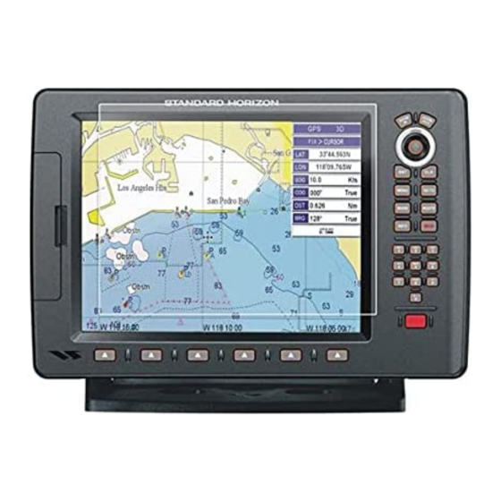
To turn Off, press and hold [PWR] until the display turns Off. Figure 3.1.0 - Start-Up page 2. When the power is first turned on, two pages the Start-Up page and the Caution pages are briefly shown before the GPS Status page. Figure 3.1.0a - Caution pages Page 22 CP500... -
Page 22: Cursor Vs. Home Mode
When the Ship Icon is shown on the Chart page (cursor is not shown) you are in Home Mode. Now as the ship moves through the water the vessel’s position will be kept in the center of the display. NOTE To change from Cursor Mode to Home Mode press [CLR]. CP500 Page 23... -
Page 23: Cursor And Menu Selection Speed
Figure 3.1.3 - Ship Icons 1. Press [MENU], move the ShuttlePoint knob to highlight SETUP MENU and press [ENT]. 2. Move the ShuttlePoint knob to highlight GENERAL SETUP and press [ENT] or move the ShuttlePoint knob to the right. Page 24 CP500... -
Page 24: Changing The Backlight And Contrast
5. Press [CLR] or move the ShuttlePoint knob to the left to exit the menu and show the Chart page. NOTE When the GPS Chart Plotter is in COURSE UP mode a small arrow icon will be shown on the Chart page indicating North. CP500 Page 25... -
Page 25: Automatic Time
By setting the time in the steps below, the time shown on the Celestial page is automatically set up. 1. Press [MENU], move the ShuttlePoint knob to highlight SETUP MENU and press [ENT]. 2. Move the ShuttlePoint knob to highlight GENERAL SETUP and press [ENT] or move Page 26 CP500... -
Page 26: Selecting Loran Td Or Other Coordinate System
The GPS Chart Plotter has preprogrammed settings allowing you to customize the look of the Chart page. The default is Sunlight, however there are other settings: Classic, NOAA, Night and Normal. Night is very useful during evening hours so not to impair night vision. CP500 Page 27... -
Page 27: Selecting Language
Point knob to the desired language and press [ENT] or move the ShuttlePoint knob to the right. 5. Press [CLR] repeatedly or move the ShuttlePoint knob to the left repeatedly to exit the menu and show the Chart page. Page 28 CP500... -
Page 28: Selecting Pages With Soft Keys
LIST. When one of the Soft Keys is pressed popup windows above each Soft Key are shown with the key description. Press the Soft Key with the desired page description and the GPS Chart Plotter will change to that page. Figure 3.6 - Screen display pages CP500 Page 29... -
Page 29: Customizing The Soft Keys
Distance: selections are Nm (Nautical Miles), Sm (Statue Miles), Km (Kilome- tres), Nm+Ft, Nm+Mt. Note when “Nm+Ft” is selected if the distance is less than 1.0Nm, it turns to Ft. When “Nm+Mt” is selected if the distance is less than 1.0Nm, it turns to Mt. Page 30 CP500... - Page 30 (default) or On All. CURSOR WINDOW By default when the cursor is moved a window is shown with the Lat/Lon Distance and Bearing from the vessels location to the cursor. This selection allows the window to be CP500 Page 31...
-
Page 31: About Page
2. Move the ShuttlePoint knob to highlight About... and press [ENT] or move the ShuttlePoint knob to the right. 3. The Information page appears on the screen (see the previous Figure). 4. Press [CLR] or move the ShuttlePoint knob to the left to exit and show the Chart page. Page 32 CP500... -
Page 32: Find Services
FIND SERVICES USING FIND SERVICES & MORE FUNCTIONS The CP500 has a dedicated [INFO] key that allows searching the optional C-MAP B /MAX C-CARD for Port Services, Ports, Tide Stations, Wrecks, Obstructions, EPPESEN Points Of Interest, Lakes, User Points, GPS Coordinates or Information on any point on the chart. -
Page 33: Port
2. Move the ShuttlePoint knob to highlight TIDE STATIONS and press [ENT] or move the ShuttlePoint knob to the right. 3. A popup window will be shown with a list of nearest Tide Stations. 4. Move the ShuttlePoint knob to highlight the desired Tide Station and press [ENT]. Page 34 CP500... -
Page 34: Wrecks
Wrecks This feature is used to locate the 20 nearest Wrecks to the position of your vessel. A Wreck is represented with an icon on the chart. See the following table: Figure 4.0.3 - Wreck icons Table CP500 Page 35... -
Page 35: Obstructions
5. Another window will be shown detailing the Obstruction information. Figure 4.0.4a - Find Obstructions 6. Press [CLR] to show the actual position of the Obstruction on the Chart page. 7. Press [CLR] again at any time to return your cursor to your vessel’s position. Page 36 CP500... -
Page 36: Lakes Information
Upon viewing the chart of a lake, you can click on the Lake Info icon to query the available information immediately displayed with many details. For example, see the following picture: Figure 4.0.5a - Example of Lakes Info CP500 Page 37... -
Page 37: Lakes By Name
1. Press [INFO]. 2. Move the ShuttlePoint knob to highlight LAKES BY NAME and press [ENT] or move the ShuttlePoint knob to the right. 3. A popup window will be shown with a list of nearest Lakes. Page 38 CP500... -
Page 38: Points Of Interest
10. Press [CLR] to show the actual position of the Point Of Interest on the Chart page. 11. Press [CLR] again at any time to return your cursor to your vessel’s position. Figure 4.0.7 - Find Points Of Interest CP500 Page 39... -
Page 39: User Points
2. Move the ShuttlePoint knob to highlight COORDINATES and press [ENT] or move the ShuttlePoint knob to the right. 3. A (Coordinate) popup window will be shown to allow you to enter in a specified Latitude and Longitude. Figure 4.0.9 - Find GPS Coordinates Page 40 CP500... -
Page 40: Information
ShuttlePoint knob through the Info Tree, all the relevant information of the selected object is shown on the lower part of the page. Figure 4.0.10 - Find Information 4. Press [CLR] again at any time to return your cursor to your vessel’s position. CP500 Page 41... -
Page 41: Max Cartography Overview
INSERTION DIRECTION Figure 5.0 - Inserting C-CARD NOTE The small connector below the C-CARD is only used by STANDARD HORIZON repair technicians. Key points are: Data Features · ISO Certification (electronic chart production process with quality certification) · Extra Large Coverage (all the C-MAP electronic chart detail and a huge coverage without having to change cartridge) ·... - Page 42 MAX data cover different areas, the GPS Chart Plotter receives data from both charts (depending on the current position). · When NT data and MAX data cover the same area, the GPS Chart Plotter receives data only from MAX chart. CP500 Page 43...
-
Page 43: Chart Functions
Zoom. When Zoom Type is set to Flexi-Zoom, a short [ZOOM IN]/[ZOOM OUT] push causes a change of chart level, while a long [ZOOM IN]/[ZOOM OUT] push (press and hold) causes an expansion or compression of the chart image, without a chart level change. Figure 6.0.0 - Zoom Type Page 44 CP500... -
Page 44: Icon Size
6. Press [CLR] until the menu disappears or an easier method is to move the ShuttlePoint knob to the left a few times. 6.0.2 Place Names Size On MAX charts it is possible to set the size of all names drawn on the charts, selecting between Standard (default), Medium and Large size. CP500 Page 45... -
Page 45: Perspective View
5. Move the ShuttlePoint knob to select the selection and press [ENT]. 6. Press [CLR] until the menu disappears or an easier method is to move the ShuttlePoint knob to the left until the Chart page is shown. Page 46 CP500... -
Page 46: Dynamic Nav-Aids
To activate this function follow the procedure: 1. Press [MENU], move the ShuttlePoint knob to highlight SETUP MENU and press [ENT]. 2. Move the ShuttlePoint knob to highlight MAX FUNCTIONS and press [ENT] or move the ShuttlePoint knob to the right. CP500 Page 47... -
Page 47: Satellite Imagery
5. Move the ShuttlePoint knob to select the selection and press [ENT]. 6. Press [CLR] until the menu disappears or an easier method is to move the ShuttlePoint knob to the left until the Chart page is shown. Figure 6.0.6 - Example of Satellite Imagery Page 48 CP500... -
Page 48: Currents Prediction
To store the date press [ENT] and the Time will be selected. d. Press Alphanumeric key or move the ShuttlePoint knob up or down to select the CP500 Page 49... -
Page 49: Chart Language
6. Press [E 6.0.8 Chart Language The CP500 may be customized to show the local language of the chart. To select the Chart Language you want: 1. Press [MENU], move the ShuttlePoint knob to highlight SETUP MENU and press [ENT]. -
Page 50: How To Show The Pictures Or Diagrams Of A Object
] to open the Full Info on the object. Note that on the Full Info, there XPAND is the small camera icon on a corner of the square containing the object icon. To see the picture press [MENU] when the object with a picture is highlighted. CP500 Page 51... -
Page 51: Enhanced Port Info
MAX C-CARDs include additional Port Services that were not EPPESEN present before. Additional attributes of Port Areas and Port Marinas have been included as Location, Country, Region, State, Harbour master telephone number etc., see the following figure. Figure 6.0.10 - Example of enhanced Port Info Page 52 CP500... -
Page 52: Creating Marks
EDITING A MARK If a Mark has previously been created and you wish to Edit it, move cursor over the top of it. 1. After a Mark is created press [E ] to show the edit popup window. CP500 Page 53... -
Page 53: Deleting A Mark Or Waypoint
1. Move the ShuttlePoint knob over the Mark or Waypoint you want to move. 2. Press [M 3. Use the ShuttlePoint knob to move the cursor. A dotted line, connecting the previous Waypoint position to the new position, is shown: Page 54 CP500... -
Page 54: Marks/Waypoints List
Figure 7.1.1a - Moving Mark or Waypoint (II) MARKS/WAYPOINTS LIST The MARKS/WPTS List shows all the Marks and Waypoints that have been stored into the CP500. To obtain the List page: 1. Created a Mark. 2. Place the cursor over the Mark, press [L ]. -
Page 55: Creating/Modify A New Mark In The User Points List
18. Press [CLR] again and the new Mark appears on the Chart page. NOTE After entering in all the Marks it is a good practice to backup the points to a User C-CARD. Refer to Section 11. Page 56 CP500... -
Page 56: Goto Cursor, Route And Mark
1. A bearing line between the vessels location and the Destination point is shown. A popup window shows the Distance (DST) and Bearing (BRG) from the vessels location to the Destination point. Figure 7.4b - GOTO menu (3) CP500 Page 57... - Page 57 5. You will notice a circle is drawn around the icon symbol. This means the GPS Chart Plotter is now navigating to the point. 6. Press [CLR] to switch to the Chart page or Highway page to start navigation to the point. Page 58 CP500...
-
Page 58: Man Over Board (Mob) Function
1. Move the ShuttlePoint knob until the cursor is over the top of the MOB icon. Figure 8.1 - Deleting MOB point 2. Press [D ELETE 3. A popup window will be shown to confirm deleting the MOB point. Move the ShuttlePoint knob to highlight YES and press [ENT]. CP500 Page 59... -
Page 59: Routes
ROUTES The CP500 has the capability to store 50 Routes with 100 Waypoints or Marks in each Route. A Route can consist of Waypoints or Marks. The difference is when a Route is made using Waypoints and the Route is deleted the Waypoints are also deleted. However if a Route is made of Marks and the Route is deleted the Marks stay in memory. -
Page 60: Changing The Name Of A Route
5. Repeat steps 3 and 4 until all Waypoints are entered into the Route. Figure 9.2 - Olympic Route creation (1) 6. Then move the ShuttlePoint knob to the last Waypoint. 7. Press [O ]. A line joins the starting Waypoint and the last Waypoint. LYMPIC CP500 Page 61... -
Page 61: Making Additional Routes
4. Repeat steps 3 and 4 until all Marks are entered into the Route. NOTE At this point the Route is saved as ROUTE01. If you would like to save the Route under a specific name follow the steps on the previous Par. 9.1. Page 62 CP500... -
Page 62: Inserting A Waypoint Into A Route
1. Move the ShuttlePoint knob to an open position (no buoy, warning etc. under the cursor) on the Chart page. 2. Press [GOTO] to show the GOTO popup window. 3. Move the ShuttlePoint knob to highlight ROUTE and press [ENT]. 4. The SELECT ROUTE popup window will be shown. CP500 Page 63... -
Page 63: Using The Shuttlepoint Knob
4. A Warning message appears to confirm. Move the ShuttlePoint knob to highlight YES and press [ENT]. The Route has been deleted. WARNING An active Route (one that you are navigating to) cannot be deleted until you stop navigation to the Route. Page 64 CP500... -
Page 64: Other Settings In Route Menu
The Route Check function is used after you have created a Route to ensure you and your vessel will not have problems while navigating. This is done by the CP500 by reviewing the Route and looking for the following hazards that may effect safe navigation. - Page 65 (like DSC, MOB, Mark). In the case of checking a single point towards which the navigation is started, the leg for which the Route Check is executed is defined by the current position (the leg’s starting point) and the Destination point (the leg’s ending point). Page 66 CP500...
-
Page 66: Tracks
10. TRACKS The CP500 has the capability to store 20 individual Tracks and record up to 10,000 Track Points. Before using the Track function you will need to setup the Track function that suits your boat. The Track function records your tracks your vessels location as it moves through the water. -
Page 67: Saving And Starting A New Track
Allows you to save a Track to one of the 5 Tracks available VISIBLE Shows or hides a Track shown in ACTIVE TRACK menu LINE COLOR Selects the color of the Track line DELETE Deletes a Track selected in the ACTIVE TRACK menu Page 68 CP500... -
Page 68: Trip Log
5. A warning popup window will be shown to confirm if you want to reset the Trip Log. Move the ShuttlePoint knob to highlight YES and press [ENT]. The Trip Log is now reset. 6. Press [CLR] to store and exit the editing mode. Figure 10.1.1 - Trip Log Reset CP500 Page 69... -
Page 69: User C-Card
5. Select YES and press [ENT] to confirm (select NO otherwise). The format of User C-CARD must be done before using a new User C-CARD: this operation prepares the User C-CARD to receive and store information. NOTE Formatting permanently erases all files previously saved on the User C-CARD. Page 70 CP500... -
Page 70: Transferring Files To The Optional User C-Card
2. Move the ShuttlePoint knob to highlight USER C-CARD and press [ENT]. A screen will appear. 3. Open the door. Change the User C-CARD into the same slot or insert a new one into the other slot. 4. Move the ShuttlePoint knob to highlight CHANGE and press [ENT] to confirm. CP500 Page 71... -
Page 71: Pages
2. Move the ShuttlePoint knob to highlight the desired page and press [ENT]. · Selection by SOFT KEY Press one of the Soft Keys under the display, then press the relating Soft Key to show the desired page. Figure 12b - Screen display pages by Soft Keys Page 72 CP500... -
Page 72: Chart Page
The focus may be changed to the other chart window with the procedure below: 1. Press any Soft Key. The Soft Key labels appear on the bottom of the screen. A [F OCUS Soft Key will be shown. CP500 Page 73... -
Page 73: Single Chart Page
It is possible to change the focus by pressing and holding [INFO] for 2 seconds (in place of 1 and 2 steps in the above procedure). 12.0.1 Single Chart page Figure 12.0.1 - Example of Single Chart Page Page 74 CP500... -
Page 74: Window Selections
12.0.2 Window Selections The default is the 2 Line Small window. The CP500 windows may be changed by the procedure below. Figure 12.0.2 - Data window layout 1. To change, press [MENU], move the ShuttlePoint knob to highlight SETUP MENU and press [ENT]. -
Page 75: Additional Functions On Chart Page
Stations and Port Icons. If the cursor is moved over the top of these icons a popup window will be shown with information about the icon. 12.0.5 Turning Off Information on Icon Points The GPS Chart Plotter allows you to select to see information on points, on all items or to Page 76 CP500... -
Page 76: Display Mode
3. Move the ShuttlePoint knob to highlight DISPLAY MODE and press [ENT]. 4. Move the ShuttlePoint knob up or down to select the preset and press [ENT]. 5. Press [CLR] until the Chart page is shown. Figure 12.0.6 - Display Mode settings CP500 Page 77... -
Page 77: Marine Settings
: Turns the Ports and Service icons On of Off. Areas along the shore with facilities for mooring, downloading and uploading of ships, generally sheltered from waves and winds. Port installations are piers, wharves, pontoons, dry docks, cranes..Page 78 CP500... -
Page 78: Depth Settings
: Turns the Points of Information On or Off. Figure 12.0.9 - Example of Roads and Points Of Interest 12.0.10 Chart Settings Settings that control how the chart features will be shown on the Chart page of the GPS Chart Plotter. CP500 Page 79... - Page 79 Plotter draws the rest of the chart using charts from above and below the current scale. When this function is turned on you will notice the display may redraw 2 to 3 times to show all the details Page 80 CP500...
-
Page 80: Underwater Objects Settings
1. To change to show the Compass Tape, select the Chart page, press [MENU]. Move the ShuttlePoint knob to highlight SETUP MENU and press [ENT]. 2. Move the ShuttlePoint knob to highlight GENERAL SETUP and press [ENT] or move the ShuttlePoint knob to the right. CP500 Page 81... -
Page 81: Highway Page
Figure 12.2a - Navigation page with Compass Tape 12.3 HIGHWAY PAGE Shows a 3D view of the vessel travelling through the water when navigating to a Destination point, Mark or following a Route. Press [ZOOM IN] or [ZOOM OUT] to change the highway scale. Page 82 CP500... -
Page 82: Celestial Page
Water Level and if the cursor is moved to the bottom of the Tide Graph the draught will show the Low Water Level. Example 1 You anchor in 15Ft of water (under your keel) at a time of day where the water is the highest CP500 Page 83... -
Page 83: Gps Status Page
4. Move the ShuttlePoint knob to highlight None (to disable) and press [ENT]. 5. Press [CLR] until the menu disappears or an easier method is to move the ShuttlePoint knob to the left until the menu disappears. 12.5.1 GPS Setup Menu Figure 12.5.1 - GPS Setup menu Page 84 CP500... -
Page 84: Nmea Display Page
The NMEA sentences read from external devices are: BWC, DSC, DSE, GGA, GLL, GSA, GSV, HDG, HDM, HDT, RMC, VHW, VTG, DPT, DBT, MTW, VWR, VWT, TLL, WPL, RTE. 12.6.0 Changing the NMEA Page Windows 1. Press [MENU], move the ShuttlePoint knob to highlight NMEA DISPLAY and press [ENT]. CP500 Page 85... -
Page 85: Nmea Data Page
2. Move the ShuttlePoint knob to highlight DATA and press [ENT]. 3. Connect the Blue wire on the GPS Chart Plotter to the junction of the Brown wire and the VHF wire. The display should look similar to the following picture. Page 86 CP500... -
Page 86: Nmea Trend
To select a NMEA Trend page: 1. Press [MENU], move the ShuttlePoint knob to highlight NMEA DISPLAY and press [ENT]. Figure 12.8 - NMEA Display menu 2. Move the ShuttlePoint knob to highlight DEPTH TREND/WIND SPEED TREND/TEMP TREND/SOG TREND and press [ENT]. CP500 Page 87... -
Page 87: Vhf Digital Selective Calling
3. The position of a vessel that transmitted a DSC Position Request Call 12.9.1 Distress Call STANDARD HORIZON GPS Chart Plotters are able to display the location of a vessel in distress when interfaced to a compatible DSC VHF with NMEA-0183 output and the radio receives a DSC Distress Call. -
Page 88: Position Request
Figure 12.9.1 - DSC Log - Distress Call 12.9.2 Position Request STANDARD HORIZON GPS Chart Plotters are able to display the location of a vessel when connected DSC VHF Radio and when a Position Request or Report Call is received. -
Page 89: Advanced Settings
13.0 INPUT/OUTPUT (NMEA, AIS, RADAR) 13.0.0 Input The CP500 has 4 NMEA inputs and 5 NMEA outputs. These Ports may be set up to receive and output the following. · NMEA-0183 - NMEA devices* set to 4800 Baud (default setting) ·... -
Page 90: Navigate
The user should enter delay values to fine adjust the position calculated. Alter : Alternate Solution (TD Coordinate System) Parameter selected by the user that is applied in the conversion of geographical coordinates Lat/Lon to TD values. To be used if the position displayed is roughly not correct. CP500 Page 91... -
Page 91: Compass
(note that in this case, if the same object type is found again later, the Alarm will be shown). The GPS Chart Plotter shows an icon on the charts that identifies when a Grounding Alarm is detected. Page 92 CP500... -
Page 92: Simulation
7. Highlight the desired Route and press [ENT]. 8. Move the ShuttlePoint knob to highlight SPEED and press [ENT]. 9. Enter in the speed you want to vessel to travel at in Simulation Mode, by moving the CP500 Page 93... -
Page 93: Dsc Polling
: Enables or disables the Auto Info. This selection is available only when Auto Position is set to Manual. If Auto Info is set to On, when receiving the Position Request it is possible to center the cursor over the top of the Position Request icon and show the Position Request popup window Page 94 CP500... -
Page 94: Ais
· Receive details from other vessels or navigation aids within VHF range. STANDARD HORIZON GPS Chart Plotters are able to display AIS Target (for collision avoidance) on the Chart page and AIS List pages when connected to a AIS Receiver (GX2100 or GX2150 STANDARD HORIZON VHF/AIS transceiver) or transponders which output NMEA-0183 VDM sentence at 38400 or 4800 baud. -
Page 95: Menu
By placing the cursor over a AIS Target icon using the ShuttlePoint knob, the following information is displayed (see the following picture): · Vessel Name · MMSI number · Radio Call Sign · SOG · COG · CPA and TCPA values Page 96 CP500... -
Page 96: List
GPS Chart Plotter. 14.5 AIS TARGET COLORS The received AIS Targets are shown in color. The color depicts the type of AIS ship shown on the Chart page. Refer to following table. CP500 Page 97... - Page 97 Figure 14.5 - Color AIS Targets Page 98 CP500...
-
Page 98: C-Weather Service
15. C-WEATHER SERVICE C-Weather is a free service available on the CP500. C-Weather service gives excellent coverage for the whole World. Weather forecasts are based on data received from the leading meteorological centers. This data is processed by Jeppesen server and made... -
Page 99: Copy From Memory Card
· Real Time View Off: the Weather data is not displayed. The layer displayed is the one selected into the previous menu item. 15.0.4 Type of Data Allows selecting the type of data among: Wind, Wave Data, Weather, Humidity, Temper- ature, Visibility. Page 100 CP500... -
Page 100: Mobilarm
STANDARD HORIZON GPS Chart Plotter. 16.0 MOBILARM-GPS CHART PLOTTER CONNECTION Connect the MOBILARM system to one of the Ports on the STANDARD HORIZON GPS Chart Plotter. Refer to Par. 2.3.2.0 “PWR & ACC1 Cable” and “NMEA Connections” and MOBILARM Owner’s Manuals for connections. -
Page 101: Software Setup
(Personal Transponder) device. When a signal from the PTX is lost for more than one minute, the MOBILARM sends a NMEA message to the GPS Chart Plotter which will produce an alarm and a popup window will be shown on STANDARD HORIZON GPS Chart Plotter. 16.2... -
Page 102: Mobilarm Ptx
It is possible to Goto (navigate) to the received MOBILARM PTX position (see Par. 16.4.1) or open the MOBILARM Alarm Status List page (see Par. 16.4.2). Selecting Goto or Alarm Status List will mute the Audible Alarm. CP500 Page 103... -
Page 103: Placing Cursor On The Ptx Icon
], when pressed will start navigation to the PTX MOB location b. [L ], when pressed will show the MOBILARM Alarm Status List page. Refer to Par. 2.4.2 for Alarm Status List. Figure 16.4.1 - Example of Goto PTX Page 104 CP500... -
Page 104: The Mobilarm Alarm Status List
(if open) and center the chart selected PTX. DELETE Deletes the selected PTX. SHOW Centers the chart on the selected PTX. SHOW ALL Selects the best chart scale to see PTX icons on the chart at the same time. CP500 Page 105... -
Page 105: Troubleshooting
Internal RAM memory to become corrupted. To solve this issue, perform a RAM clear (refer to Section 18). NOTE After performing a RAM Clear all Marks, Routes and tracks will be erased. To backup these points refer to Section 11 for details. Page 106 CP500... -
Page 106: Technical Tests
[CLR]). 18.0.1 DIM Menu To select the desired value for brightness and keypad light. Contrast Each time you move the ShuttlePoint knob to right, the screen will decrease brightness, move it to the left to increase brightness. CP500 Page 107... -
Page 107: Cartridges (Used By Standard Horizon Technicians)
4. if there is a User C-CARD inserted in the slot, the message USER C-CARD is shown. C-CARD Connector Indicates if there is a malfunction in the connector. 18.0.3 Serial Ports (used by STANDARD HORIZON Technicians) If you are having problems receiving data from the position-finding instrument, this test should help determine the problem. -
Page 108: Specifications
VDM, VHW, VTG, VWR, VWT, WPL 9.7" [246mm] MENU GOTO MARK ROUTE INFO 0.8" [21mm] 0.7" [16.5mm] 10.8" [274mm] 0.7"[16.5mm] 11.3" [286.5mm] Ø0.2" [Ø5.5mm] 0.8" 3.9" [100mm] 0.8" [20mm] [20mm] 15.4" [391mm] 0.2" [4.6mm] Figure 19 - CP500 Dimensions [inch/mm] CP500 Page 109... - Page 109 12.4” [315mm] 0.17” [O4,5mm] - MOUNTING HOLES 4 POS. CUTTING LINE R15 - 4 POS. 10.9” [278mm] UNIT SHAPE PROTECTIVE COVER SHAPE 16.14” [410mm] Figure 19a - CP500 Flush Mount cutout (dimensions are in mm) Page 110 CP500...
-
Page 110: Optional Waas Gps Receiver Specifications
Channels 32 + 18 Acquisition Time Reacquisition < 1 second Hot Start 1 second Warm Start 29 seconds Cold Start 29 seconds Accuracy < 10Ft with SBAS < 2.0Mt NMEA Output Messages GGA, RMC, GSA, GSV, TXT CP500 Page 111... -
Page 111: Appendix: Terms
(GPS). The smaller the HDOP/VDOP value, the more accurately the position fix is provided. HEIGHT – The current Tide height referred to the vertical cursor. HIGH WATER – The maximum level of the Tide height in 24 hours. Page 112 CP500... - Page 112 70Mt (230Ft) in height and up to 600Mt (2.000Ft) in diameter. Position Request – Marine DSC VHF Function of transmitting a GPS position to another Marine DSC VHF. When GPS Chart Plotter is connected to STANDARD HORIZON GPS the position of another vessel is shown on the Chart page.
-
Page 113: Analytical Index
Chart Orientation Resolution ........91 Auto Info settings ............77 Chart page ............23, 73 Auto Position ............... 94 Chart Scale ..............76 Auto Switch ..............19 chart scale ............20, 45 auto-test ..............107 chart scale selection ............ 44 Page 114 CP500... - Page 114 Dynamic Currents ............42 DATE ................. 112 Dynamic Nav-Aids ..........42, 47 Date ..............76, 93 DATE FORMAT ............30 Datum ..............91, 111 Daylight Savings Time ......... 26, 30 DB9 ................16 EDIT ..............55, 65 CP500 Page 115...
- Page 115 GGA ........... 85, 91, 109, 111, 112 ISO Certification ............42 GLL .............. 85, 90, 109 Italian ................28 GMDSS ............... 88, 112 GNSS Systems ............111 GOTO ............21, 57, 105 Goto ................103 Japanese ..............28 GOTO CURSOR ............57 Page 116 CP500...
- Page 116 North Up ............... 25, 30 MDS-10-4 ..............11 Norwegian ..............28 MDS-10-5 ..............11 NT+/MAX .... 10, 20, 21, 33, 71, 73, 80, 92, 109 MDS-8 ................11 NT/NT+ ................ 43 MDS-9 ................11 NTSC ..............10, 18 CP500 Page 117...
- Page 117 Position Request ........88, 89, 94, 113 sailboat ................ 10 Position Request Call ..........88 satellite ..........23, 48, 84, 113 Position Send Call ............88 Satellite Imagery ............48 Power Consumption ..........109 save the file ..............71 Page 118 CP500...
- Page 118 User Points ........... 21, 33, 40, 109 UTC ................26 Target ................95 UTM ..............27, 91 TCPA ..............95, 96 TCPA Alarm ............95, 96 TCPA Limit ............95, 96 TD ................. 27, 91 VAD ................80 CP500 Page 119...
- Page 119 ................73 WAAS GPS ............106, 111 zoom factor ..............45 WAAS/EGNOS ............84 ZOOM IN .............. 20, 44 WARNING ..............4 ZOOM OUT ............20, 44 warning ................ 47 Zoom Type ..............44 Warning Icon ............... 48 Page 120 CP500...
- Page 120 United States: To receive warranty service, the purchaser must deliver the Product, transportation and Insurance prepaid, to STANDARD HORIZON (Marine Division of YAESU USA) - Attention Factory Service - 6125 Phyllis Drive - Cypress, CA 90630, include proof of purchase indicating model, serial number and date of purchase.
-
Page 121: Declaration Of Conformity
Directive 1999/5/EC, with the provisions of Annex III (Conformity Assessment procedure referred to in article 10) Type of Equipment: 12” Chart Plotter for Marine Navigation with external GPS RX. Brand Name: Standard Horizon Model Number CP-500 Manufacturer TWS S.r.l...
Need help?
Do you have a question about the CP500 and is the answer not in the manual?
Questions and answers