
Subscribe to Our Youtube Channel
Related Manuals for SDMO R33C3


Summary of Contents for SDMO R33C3
- Page 1 User and maintenance manual for generating sets R33C3 Translation of the original instructions 33504023701NE_2_1...
-
Page 3: Table Of Contents
CONTENTS 1. Preface ........................................4 General recommendations ............................... 4 1.1. Warnings ....................................4 1.2. Pictograms and their meanings ..............................5 1.3. Safety instructions ..................................8 1.4. 1.4.1 General guidelines ..................................8 1.4.2 Electrical safety precautions ..............................10 1.4.3 Safety precautions in case of electrical shock ........................11 1.4.4 Safety precautions relating to fire, burns and explosions ....................... - Page 4 6. Using the generator set ..................................50 Pre-Start Inspection ................................50 6.1. Generator set with NEXYS control panel ..........................53 6.2. 6.2.1 Control panel presentation ..............................53 Introduction to pictograms ............................54 6.2.1.1. 6.2.2 Manual starting ..................................55 6.2.3 Switching off ................................... 56 6.2.4 Alarms and faults ..................................
- Page 5 TABLE OF ILLUSTRATIONS Figure 1 : Warning pictograms .................................. 5 Figure 2 : Pictograms indicating prohibited activities ..........................5 Figure 3 : Pictograms indicating compulsory operations ........................... 6 Figure 4 : Information pictograms ................................6 Figure 5 : Specific pictograms ................................... 7 Figure 6 : Pictograms relating to battery operations ..........................
-
Page 6: Preface
1. Preface 1.1. General recommendations The information contained in this manual is taken from technical data available at the time of print. In line with our policy of continually improving the quality of our products, this information may be amended without warning. Read the safety instructions attentively in order to prevent any accident, incident or damage. -
Page 7: Pictograms And Their Meanings
1.3. Pictograms and their meanings The aim of the pictograms is as follows: To draw the attention of the operator or maintenance technician to the potential dangers. To explain how to act in the interest of personal safety and to avoid damaging the equipment. The safety pictograms present on the equipment are explained below. -
Page 8: Figure 3 : Pictograms Indicating Compulsory Operations
Reading Wearing suitable Wearing suitable manual protective goggles protective clothing equipment and ear defenders is compulsory compulsory is compulsory Lifting point Forklift required for Battery charge required lifting must be checked Periodic maintenance compulsory Figure 3 : Pictograms indicating compulsory operations Battery isolating External... -
Page 9: Figure 5 : Specific Pictograms
Flammable product, Reading the manual for the equipment is Do not smoke or create sparks or flames compulsory Fuel supply Securing straps routing point - Selection valve - Figure 5 : Specific pictograms Rinse any splashes of acid on the skin or in the eyes using clean water. -
Page 10: Safety Instructions
1.4. Safety instructions RETAIN THIS MANUAL This manual contains important instructions which must be followed when installing or carrying out maintenance on a generating set and batteries. IMPORTANT - SAFETY ADVICE If any parts of this manual are not understood, or in case of doubt, contact your nearest agent in order to receive an explanation or demonstration to allow the equipment to be used correctly. - Page 11 Maintaining the equipment Personnel skills: Ensure that the maintenance operations are performed on the equipment by appropriately trained personnel. Personnel protection: Wear suitable clothing and protective goggles. Remove any personal belongings that may hinder the operation: watch, bracelet, etc. Fit a panel over the controls of the equipment to prevent any attempt to start. Disconnect the battery (and pneumatic starter if fitted) before beginning any maintenance operation.
-
Page 12: Electrical Safety Precautions
Operating site Maintenance: Clean the entire operating site regularly with suitable cleaning materials. The presence of dangerous or combustible materials inside premises must be limited to the operating requirements. Access: Prohibit free access to persons who are not part of the establishment, except for those designated by the user. Respecting the environment: Drain and dispose of engine oil in a specially provided container (fuel distributors can collect your used oil). -
Page 13: Safety Precautions In Case Of Electrical Shock
1.4.3 Safety precautions in case of electrical shock In the event of an electric shock, observe the following instructions: Avoid direct contact both with the live conductor and the victim's body. Shut off the power immediately and activate the emergency stop for the equipment concerned. - Page 14 Fuels Respect current local regulations regarding the equipment and fuel used (petrol, diesel and gas). Top up the engine with fuel when the engine has stopped (except for equipment with an automatic filling system). Smoking, using a flame or producing sparks are forbidden while the fuel tank is being filled.
-
Page 15: Toxic Risk Safety Precautions
1.4.5 Toxic risk safety precautions DANGER EXHAUST GAS - TOXIC PRODUCTS - TOXIC RISK - Exhaust gas Use suitable ventilation to release the exhaust gas outside and prevent it from accumulating. Respect current local regulations regarding the equipment and fuel used (petrol, diesel and gas). -
Page 16: Precautions For Risks Relating To Handling Phases
Battery electrolyte Avoid all contact with the skin and eyes. Wear suitable protective goggles and clothing and strong alkali-resistant gloves for handling the electrolyte . If splashes get into the eyes: Rinse immediately with running water and/or a 10% diluted boric acid solution. Consult a doctor immediately. -
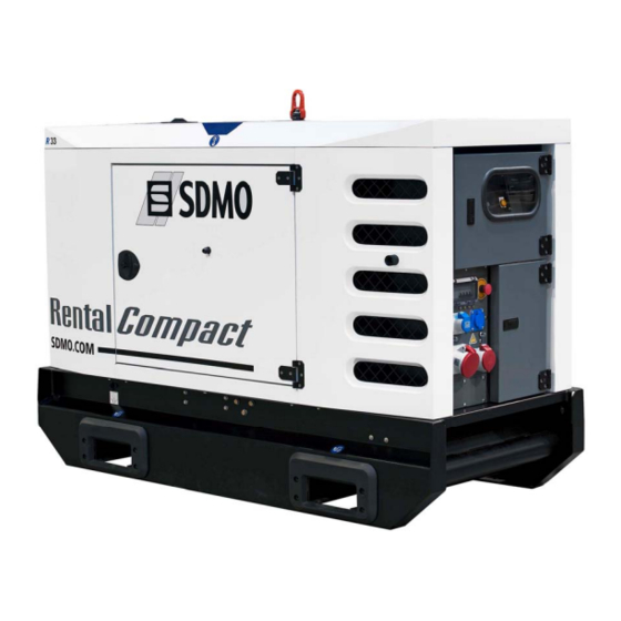
Page 17: General Description
2. General description 2.1. Description Overview Figure 7 : General description of the generating set Acces to maintenance area Acces to control unit Lifting ring Acces to power connections Forklift grooves Drawbar 15/242... -
Page 18: Figure 8 : General Description Of The Generating Set (Continuation)
Figure 8 : General description of the generating set (Continuation) Protective grille Alternator External fuel supply combined tap Battery isolating switch (optional) Starter battery Charging alternator 16/242... -
Page 19: Figure 9 : General Description Of The Generating Set (Control)
Control Figure 9 : General description of the generating set (control) Control unit Working hours counter Emergency stop Power circuit breaker Socket control panel Connection terminal block Note : Photo presented with the Nexys control unit. 17/242... -
Page 20: Technical Specifications
2.2. Technical specifications RENTAL POWER / R33C3 Range / Generating set type Weights and Dimensions Dimensions with high autonomy tank Dimensions l x w x h 2200 mm x 1000 mm x 1528 mm Weight: 1100 kg à vide / 1300 kg en ordre de marche... - Page 21 Alternator data ● Compliant with NEMA MG21 standards, UTE NF C51 111, ● The alternator is protected against short circuits VDE 0530, BS 4999, IEC 34.1, CSA ● Vacuum impregnation, epoxy winding, IP23 protection rating Type LEROY SOMER LSA42.2L9 Number of phases Power factor (cos Phi) Number of poles Excitation type...
-
Page 22: Identifying Sets
2.3. Identifying sets Generating sets and their components are identified by means of identification plates. The precise rules for identifying each major component (engine, alternator, etc.) are set out in each manufacturer's documentation contained in the appendices of this manual. 1 - Generating set 9 - Maximum ambient temperature for the rated power (°C) -
Page 23: Fluid Retention
2.4. Fluid retention Any outflow of the fluids contained in the generating sets (fuel, oil and coolant, or rainwater or condensation) will be collected in a retention container. The containers have a capacity which allows 110% of the fluids contained in the generating set fitted with this option to be collected. Figure 11 : Fluid retention container The generating sets are fitted with a visual alarm warning when the upper limit of the retention container has been reached. -
Page 24: Fuels, Lubricants And Coolants
2.5. Fuels, lubricants and coolants All specifications (product features) are given in the engine and alternator maintenance manuals attached to this manual. In addition to these, we recommend the fuels, lubricants and coolants mentioned in the "Specifications" section. 2.5.1 Fuel specifications General quality requirements The quality of the fuel is essential for engine performance. - Page 25 General specifications for diesel fuel The fuel used must have the following characteristics (non-exhaustive list): The sulphur content must meet the current emissions regulations in the region where the generating set is used. For the United States and countries respecting the EPA regulation Only use Ultra Low Sulphur Diesel (ULSD) fuel with a maximum sulphur content of 15 mg/kg for Interim Tier 4 and Tier 4 certified engines.
-
Page 26: Lubricant Specifications
2.5.2 Lubricant specifications Essential for the correct operation of the engine. The oil should be selected according to its use. Besides the lubrication function, oil should also: cool certain parts; protect metal parts against corrosion; improve the sealing, in particular between pistons, piston rings and cylinders; remove impurities (to the filter). -
Page 27: Coolant Specifications
Characteristics of GENLUB TDX 15W40 oil Performance GENLUB TDX oil is a 15W40 multigrade mineral oil which meets the following specifications: ACEA E3 and API CG-4. ACEA E3: oil with superior viscosity stability, suited to extended oil change intervals and severe conditions of use. API CG-4: oil particularly effective to meet the emissions requirements. - Page 28 Specifications of GENCOOL PC -26 coolant Performance GENCOOL PC -26 coolant is a ready-to-use cooling fluid which provides a high level of protection and is produced from an antifreeze approved by the majority of manufacturers (Power Cooling concentrated antifreeze). It offers the following: Improved anticorrosion: improves the effectiveness and service life of the cooling system.
-
Page 29: Transporting The Equipment
3. Transporting the equipment 3.1. Warnings concerning transport It is prohibited to operate generating sets whilst they are being transported. IMPORTANT 3.2. Preparing for transport Before the equipment is transported, perform the following operations: Close the tap on the oil top up tank outlet. Fill up the oil top up tank with oil. -
Page 30: Generating Sets On Trailers
3.3.2 Generating sets on trailers Hitching and unhitching the trailer 3.3.2.1. Jockey wheel for M3128 Jockey wheel for and M3129 M3126 type trailers and M3127 type trailers Before hitching the trailer, check the hitching system on the towing vehicle; this must be perfectly compatible with the trailer. Towing a trailer with a non-compliant device (bar, cables, lashing, etc.) runs the risk of serious accidents. - Page 31 Hitching a trailer fitted with a hitching ring Drive the towing vehicle or bring the trailer up to the hitching point, then: With the jockey wheel touching the ground, place the stabiliser (1) in the top position: Loosen the jaw of the stabiliser (2) with its lever; Raise the stabiliser fully;...
- Page 32 Attach the unlocking cable to the hitching plate on the towing vehicle. Examples of how to attach the hitching cable If the hitching ring is not correctly connected to the hitching hook, the trailer will become separated from the towing vehicle. In this case the unlocking cable actuates the parking brake (which then becomes an emergency brake).
- Page 33 Unhitching a trailer fitted with a hitching ring Immobilise the trailer: Chock the wheels; Apply the parking brake: Raise the parking brake lever (10) fully. Disconnect the electrical cable plug controlling the lights, indicators, etc. from the socket on the towing vehicle. Remove the unlocking cable on the towing vehicle.
-
Page 34: Check Before Towing
Check before towing 3.3.2.2. Before first use, it is essential to check the tightness of the wheel bolts. IMPORTANT Before towing, check the following: Wheel tightness. Hitching hook locked. Tyre pressure. Signalling lights working. Enclosure doors closed. Parking brake released. Guide wheels (jockey wheels) and stands lifted and locked. -
Page 35: Rail Transport
Lights / signalling Warning lights are obligatory for on-road driving. Signalling must comply with regulations in force in the country of use. Front reflective devices (white) Red rear lights + direction indicators + stop lights Rear reflective devices (red triangle) Side reflective devices (orange) Figure 12 : Example of French signalling... -
Page 36: Shipping
3.5. Shipping 3.5.1 Generating sets with and without an enclosure Transportation must be carried out in accordance with the rules of shipping. Generating sets must be transported in a shipping container. When shipping generating sets in containers, the following steps must be observed: Choose transport equipment appropriate for this usage, and having all the safety guarantees both in terms of load-bearing capacity and securing devices. -
Page 37: Installation - Connections
4. Installation - Connections 4.1. Unloading the generating set 4.1.1 Choosing the location When choosing where to site the generating set, bear in mind the: - proximity to the electrical distribution panel; - nuisance caused by the noise; - fuel supply; - burnt gas evacuation;... -
Page 38: Safety During Unloading
4.1.2 Safety during unloading Always follow the safety instructions before unloading IMPORTANT - The lifting machinery or equipment is suitable for the work required and the weight of the generating set. This is indicated on the generating set's identification plate. - The sling is correctly positioned in the central lifting eye or the lifting arms are correctly positioned in the fork-lift pockets intended for this purpose. -
Page 39: Fork Lift Truck
Fork lift truck 4.1.3.2. Position the arms of the forklift truck in the forklift pockets (no. 2). Lift the equipment, handling it gently. Set down the generating set in its unloading position. Figure 14 : Points used for lifting and moving 4.1.4 Moving the generating set Whenever moving the generating set, ensure suitable equipment is used (e.g. -
Page 40: Connecting The Generating Set
4.2. Connecting the generating set 4.2.1 Connection summary This diagram can be used to retrace the different steps enabling the generating set to be correctly connected. TT earthing system "EDF application" option (France only) Identify the type of differential protection fitted on the generating set Fixed differential protection Adjustable differential protection... -
Page 41: Protecting People And Equipment
4.2.2 Protecting people and equipment Earthing system principle 4.2.2.1. The Earthing system, or SLT (formerly Neutral system) of the electrical installation defines the situation of the generating set neutral in relation to earth and the grounds of the electrical installation at the user end. Our generating sets are designed to operate with the TT system (or EDF application depending on the option, for France only). -
Page 42: Installing The Differential Protection
Installing the differential protection 4.2.2.3. The generating set is equipped with a residual current device in order to guarantee individuals are protected from electric shocks with the TT system. This may be fixed ("vigi" unit) or adjustable (Resys) depending on the option chosen. •... -
Page 43: Setting The Generating Set Differential Protection
Setting the generating set differential protection 4.2.2.4. The setting of the generating set's residual current device is guaranteed by a differential relay fitted near the control unit (type A / AC or B depending on the generating sets). As a result, two parameters relating to the downstream device (terminal circuit) must be set: Current threshold: the generating set's differential relay must be three times more sensitive than that of the terminal circuit. - Page 44 Type B differential relay: Use: Differential relay for which operation is guaranteed: • as in the case of type A; • for residual sinusoidal currents up to 1000 Hz; • for residual sinusoidal currents superimposed on a pure continuous current; •...
-
Page 45: Earthing The Generating Set
Earthing the generating set 4.2.2.5. Risk of electric shock. Before use, the generating set must always be earthed. Protection against electric shocks is only effective once the earthing connection has been made. Disconnect the battery leads, starting with the negative lead (-), or use the battery isolating switch before DANGER carrying out any operations on the generating set. -
Page 46: Making The Connections
Length of earthing Nature of ground rod (in metres) Check the length of the earthing rod depending on the Thick arable land, damp nature of the ground and adapt if necessary. compact backfill Thin arable land, gravel, rough The equipment supplied is not suitable for backfill bare stony soils, dry sand or impermeable rock. -
Page 47: Selecting The Power Cables
Selecting the power cables 4.2.3.2. The calculation rules used to choose the power connection cable size are defined below: Identify the current shown on the generating set's identification plate. From the table below, select the circuit breaker rating directly above the current shown on the generating set's identification plate. -
Page 48: Connecting The Generating Set To The Installation
Connecting the generating set to the installation 4.2.3.3. Risk of electric shock. Before use, the generating set must always be earthed. Protection against electric shocks is only effective once the earthing connection has been made. Disconnect the battery leads, starting with the negative lead (-), or use the battery isolating switch before DANGER carrying out any operations on the generating set. - Page 49 Connect power connection cables onto bars (N/L0-L1-L2-L3 or N2-R2-S2-T2) using the terminals (no.5) or clamps (no.6). Slide the cable router flap towards the inside of the generating set until it makes contact with the power connection cables then retighten the two knobs; close the access door to the power section back up again.
-
Page 50: Connecting The Battery Or Batteries To The Generating Set
Connecting the battery or batteries to the generating set 4.2.3.4. Always ensure that the polarities of the battery and starter motor correspond. Never swap the positive and negative battery terminals when connecting them. This could cause severe damage to the electrical equipment. IMPORTANT To connect the battery: 1. -
Page 51: Preparing For Operation Of The Generating Set
5.3. Preparing for operation of the generating set Become familiar with the controls useful to operate the generating set. Read and understand the "user" menus of the control unit. Become familiar with the maintenance plans for the generating set . Become familiar with the operation of the generating set at no load or under load. -
Page 52: Using The Generator Set
6. Using the generator set 6.1. Pre-Start Inspection Inspecting the engine compartment Make sure there is no combustible material near the engine or battery. Also, check to make sure that the engine and battery are clean. If combustible materials or dust are found near the engine or battery, remove them. - Page 53 Checking the coolant level Remove the radiator filler cap only after the engine has cooled to room temperature. Place a waste cloth over the cap, and loosen the cap about a half-turn or stand the lever to the upright position to release internal pressure.
- Page 54 Checking the fuel pre-filter The fuel is highly flammable and its vapours are combustible. The fuel pre-filter must only be bled when the engine is stopped and cold. Danger Check that there is no water or sediment at the bottom of the pre-filter. If necessary, drain the pre-filter using the following procedure: Place a suitable container under the drain plug prefilter Undo the drain plug (A) at the bottom of the pre-filter by two or three turns.
-
Page 55: Generator Set With Nexys Control Panel
6.2. Generator set with NEXYS control panel 6.2.1 Control panel presentation Figure 16 : View of the front side Emergency stop button for switching off the generating set in the event of a fault which could endanger personnel or damage equipment Key switch for starting up/shutting down the module and RESET function Electronic card protection fuse... -
Page 56: Introduction To Pictograms
Figure 17 : Description of the LEDs A lit LED indicates: Module being supplied (green, lights up and remains lit) Emergency stop activated (control panel or external emergency stop) (red, lights up and remains lit) Visualisation of starting phase and speed/voltage stabilisation (flashing) and generating set operating OK or set ready to generate (green, lights up and remains lit) General alarm (orange, flashing) General fault (red, flashing). -
Page 57: Manual Starting
6.2.2 Manual starting Check that the generating set circuit breaker has triggered. Danger connect the generating set battery. turn the key switch to the ON position (without forcing it) All of the LEDs light up for 2 seconds, to confirm that they are operating correctly. If the LEDs do not light up, check the protection fuse and replace it if necessary. -
Page 58: Switching Off
6.2.3 Switching off trigger the circuit breaker located at the base of the centre console Let the motor run under no load for 1 to 2 minutes to allow it to cool. press the "STOP" button to stop the generating set. switch off the MICS Nexys module by switching the key to "OFF"... - Page 59 List of faults which will cause the generating set to stop and generate a fault code Associated message Low coolant level fault: indicates that the level of coolant is low in the radiator (linked to a two second time delay). Overload or short-circuit fault (optional): with the circuit breaker SD contact closing (overload or short-circuit), the generating set switches off immediately also causing the...
-
Page 60: Murphy Diagnostic Module
6.2.6 MURPHY diagnostic module The fault finding module (MDDM) is an indicator for analysis and fault finding designed and manufactured for reading information available on the J1939 CAN Bus. The fault finding module is easy to use and will enable you to view the values of the various engine parameters and engine operating status codes. - Page 61 The following diagram shows the structure of the main menu and how to go to each parameter: 59/242...
- Page 62 The Parameter menu: to navigate in this menu simply use the arrow buttons separately. The sub-menus: The sub-menus are available at the end of the parameter menu. To go to these sub-menus, scroll through the parameters using the ▲ and ▼ buttons until you reach the required sub-menu. C- The Sub-menus.
- Page 63 D-Displaying the active service codes: The fault finding module enables the machine faults and alarms to be displayed in real time. When a fault appears, the display shows the message "SrvcCode" every five seconds between displaying the current parameters. The orange LED will light up when an alarm code is displayed (engine does not stop), the red LED will light up when a fault code is displayed.
- Page 64 E-display of machine codes programmed: The MDDM can display the codes of services programmed in the ECU memory. These programmed service codes are useful for generating set fault finding and maintenance. To display the programmed codes, scroll through the parameters until you reach the following sub-menus: In the event that there are no programmed codes to display, the following screen will appear: The purpose of programmed codes is to create a fault log, which is used to determine recurrent faults and thereby carry out effective corrective and preventive maintenance on the engine;...
- Page 65 F)-Fault finding module internal errors. Like any equipment using internal memory and a program, the fault finding module generates fault codes. Two types of code can be recognised: - Address Claim Procedure Errors - Run Time Bus Errors. Address Claim Procedure Errors (ACP-Err): The following fault codes relate to the switching on of the fault finding module.
-
Page 66: Generator Set With Telys Control Panel
6.3. Generator set with TELYS control panel 6.3.1 Control panel presentation View of the front panel 6.3.1.1. Figure 19 : View of the front panel Emergency stop button (AU) for switching off the generating set in the event of a fault which could endanger personnel or damage equipment. -
Page 67: Figure 20 : Description Of The Leds
Figure 20 : Description of the LEDs A lit LED indicates: Alarm activated (flashing yellow). Fault found (flashing red). Module on (green, on continuously). Figure 21 : Close-up of USB ports USB key connection (HOST): file transfer between USB key and TELYS and vice versa. Connection for microcomputer (DEVICE): file transfer between PC and TELYS and vice versa, main module power supply. -
Page 68: Description Of The Screen
Description of the screen 6.3.1.2. The screen is backlit and requires no contrast adjustments. This screen is divided into 4 zones. SERIAL No.: 08030010000 SOFTWARE: 5.3.5 NOMINAL VOLTAGE: 400V FREQUENCY: 50Hz NOMINAL KW: 320kW EARTH SYSTEM: TNS Figure 22 : Description of the screen (example) Zone 1: in this zone, the status of the generating set is displayed Zone 2: in this zone, pictograms relating to dimensions measured are displayed, as well as Alarm and Fault pictograms Zone 3: in this zone, the measured values corresponding to the measured dimensions are displayed with the corresponding units... -
Page 69: Description Of The Pictograms In Zone 1
Description of the pictograms in zone 1 6.3.1.3. Zone 1 pictograms Pictograms Display Activation conditions Fixed TELYS in manual mode (MAN) For 5 seconds when switching from Flashing AUTO to MAN mode "MAN" mode Fixed TELYS in automatic mode (AUTO) For 5 seconds when switching from Flashing MAN to AUTO mode... -
Page 70: Description Of The Pictograms In Zone 3
Description of the pictograms in zone 2 6.3.1.4. Alarm and fault pictograms in zone 2 All the pictograms in this zone are activated when TELYS is initialised. Data displayed Fuel level indicator Alarm / Fault Alarm / Fault low fuel level high fuel level Coolant level / temperature indicator Alarm... -
Page 71: Description Of The Pictograms In Zone 3
Description of the pictograms in zone 3 6.3.1.5. Zone 3 pictograms All the pictograms for these zones are activated when the TELYS is initialised. The pictograms below are shown for information only. Generating set stopped Screen No. Pictograms Data displayed Fuel Level Indication High-temperature (HT) - Page 72 Screen No. Pictograms Data displayed Alternator V1 single Voltage Indication Alternator V2 single Voltage Indication Alternator V3 single Voltage Indication Alternator Frequency Indication Alternator U12 compound Voltage Indication Alternator V2 single Voltage Indication Alternator V1 single Voltage Indication Alternator Frequency Indication Alternator V1 single Voltage Indication Alternator phase 1 Current Indication Alternator Frequency Indication...
-
Page 73: Display Of Messages In Zone 4
Screen No. Pictograms Data displayed Fuel Level Indication Battery Voltage indication Battery Ammeter Indication Total Reactive Power Indication Alternator U12 compound Voltage Indication Total Active Power Indication Alternator Frequency Indication Order of appearance of screens based on the type of network with the genset started. Type of line Order of appearance 3P+N... - Page 74 Generating set stopped Screen Screen Data displayed MANUAL OPERATION Operation mode - genset in MAN mode ready to Press START start to start Date and time (depending on settings) 24/08/2005 13:12 AUTOMATIC OPERATION Operation mode - genset in AUTO mode ready to IMPORTANT start IMMEDIATE START-UP...
-
Page 75: Starting
Generating set start-up Screen Screen Data displayed STARTING Operating phase - genset starting IN PROGRESS Date and time (depending on settings) 24/08/2005 13:12 AIR PREHEATING Operating phase - air preheating prior to genset starting Countdown of the air preheating delay 10sec Date and time (depending on settings) 24/08/2005... - Page 76 Screen Screen Data displayed AUTOMATIC STOP Operation mode - operation in AUTO mode IN PROGRESS Genset cooling in progress Countdown of the Engine Stop delay (cooling) OR G 10 Gradual Stop delay (Water temperature) OR COOLING Overload Gradual Stop delay OR No Load Test 1min30 delay Date and time (depending on settings)
- Page 77 Generating set stoppage Screen Screen Data displayed STOPPAGE Genset stoppage G 11 IN PROGRESS Date and time (depending on settings) 24/08/2005 13:16 Change of operation mode (switch from MAN mode to AUTO mode when an automatic start demand is issued) Screen Screen Data displayed...
- Page 78 6.3.2 Starting Check that the generating set circuit breaker has triggered. Danger Connect the generating set battery Turn the key switch to the ON position (without forcing it to the ON position), the ON lamp will light up (if the lamp does not light up, check and replace the fuse if necessary) Test the Alarm and Fault LEDs (menu 15 –...
-
Page 79: Switching Off
6.3.3 Switching off Open the circuit breaker manually by selecting menu 12 "CONTROL LOAD" The following display will disappear (supply stopped) Press the STOP button The following screen is displayed and the generating set will stop IN PROGRESS 24/08/2005 13:12 Switch TELYS off by turning the key to "OFF"... -
Page 80: Activation Of An Alarm Or Fault
Faults All faults will cause: the generating set to stop: immediate or gradual stop (coolant temperature and overload or short circuit) the red LED to flash "General fault". In conjunction with this LED: a flashing pictogram appears on the LCD screen message on graphic display (example) representing the circuit affected by the fault and the FAULT... -
Page 81: Activation Of An Alarm And A Fault
Activation of an alarm and a fault 6.3.4.3. The appearance of an alarm and a fault causes: The yellow and red LEDs to flash the related screen to be displayed (example below) FAULTS 1/2 FAULT Emergency Stop If several faults are present, the number of faults is 25/12/05 15:30 displayed at the top of the screen. -
Page 82: Engine Fault Codes Display
Engine fault codes display 6.3.4.4. Certain alarms and engine faults generate specific fault codes. These codes are standardised according to the J1939 and/or J1587 standards. Terminology used by the SAE CAN J1939 standard SPN: Suspect Parameter This represents the system or component at fault, for example: SPN 100, Number indicates an oil pressure problem or a problem with the oil pressure sensor. -
Page 83: Horn Reset
In the event of a fault, the screen will display the following message: FAULT Engine fault code. ALARM Pressing OK will display fault finding information. In addition, appendix D indicate the meaning of the ENGINE GENERAL 110 18 code. The checking and maintenance operations to 25/12/2005 15:30 carry out in order to solve the fault are included in the... -
Page 84: Table Of Maintenance Operations
7.3. Table of maintenance operations 10 h 20 000 h OPERATIONS 250 h 500 h 1000 h 1500 h 3000 h 2 years Daily 3 years Generator set • Check the general condition ● • Check the tightening torques ● •... -
Page 85: Cover Maintenance
7.4. Cover maintenance The sealing between the cover and the frame and between the frame and the retention tank is ensured by a gasket. It is essential to replace the gasket if the cover has been removed. IMPORTANT Users must maintain the enclosures and base frames to ensure that the paintwork retains all its protective properties. 7.5. -
Page 86: Fault Finding
7.6. Fault finding Refer to the user manual and engine and alternator maintenance manuals appended. Additionally, in the event of an abnormal rise in engine temperature, check that the radiator is clean. 7.7. No load and under load tests Notes on operation at no load and under load: When operating at no load or low load (<... -
Page 87: Starter Batteries
8. Starter batteries DANGER Risk of explosion or fire (oxygen and hydrogen present). The battery must never be exposed to any naked flames or sparks. Risk of sparks forming and an explosion. When fitting the battery, never invert the polarities. Do not short the battery terminals with a tool or other metal object. -
Page 88: Charging The Battery
8.3. Charging the battery Highly discharged or sulphated batteries (formation of whitish lead sulphate deposit on the plates, which becomes hard) can no longer regenerate or be charged in a generating set. A discharged battery should be recharged immediately, or else it will suffer irreparable damage. IMPORTANT Battery charge Example of charge:... -
Page 89: Fault Finding
8.5. Fault finding Fault observed Probable origin Measures or observations Cool Incorrect composition The acid heats up when a new battery is Incorrect storage Charge the battery filled Prolonged storage in a damp place Check the acid density The acid escapes through the filler holes The battery is too full Reduce the battery fluid level Battery tray not leaktight... -
Page 90: Options
9. Options 9.1. Dual frequency This operation must be carried out by a qualified electrician. These operations must only be carried out when the generating set is stopped, until you are instructed to start up the generating set. IMPORTANT • Close the battery isolating switch to turn on the TELYS 2. - Page 91 • As not all the settings are available, go to the "37 3 SETTINGS INSTALLER ACCESS" menu to enter the code "1966" using the knob to call up the desired menus. 34 50Hz <> 60Hz 35 NOMINAL VOLTAGE 36 PARAMETERS 37 INSTALLER ACCESS INSTALLER ACCESS Enter password...
- Page 92 • Select the desired configuration using the configuration option selector located next to the TELYS 2 control unit. Configuration selector • Start up the generating set by pressing the "START" button. MENU • Adjust the voltage after starting up the generating set using the 2003R08 potentiometer.
-
Page 93: Neutral System
9.2. Neutral system Turn the switch to the desired neutral system. Ф Select the neutral system with the generating set switched off. Important 9.3. Fuel supply valve The 3-way valve is used to select between the generating set fuel tank and an external fuel supply. Valve in vertical position (no. - Page 94 92/242...
-
Page 95: Appendix
10. Appendix 10.1. Appendix A – Engine user and maintenance manual 93/242... - Page 96 94/242...
- Page 97 User guide and maintenance manual 99610-29120 33522051001_3_1 01/07/2009 95/242...
- Page 98 96/242...
-
Page 99: Maintenance Manual
OPERATION & MAINTENANCE MANUAL 199610-29120 The operator and supervisor are requested to read this Oper- ation and Maintenance Manual carefully before operating the engine or conducting inspection and maintenance. Never operate the engine or conduct maintenance work with- out completely understanding this manual. July 2009 Pub. - Page 100 INTRODUCTION This operation and maintenance manual contains detailed operation, inspection and maintenance information for engines from Mitsubishi Heavy Industries, Ltd. Please read this manual thoroughly before proceeding with operation, inspection, and maintenance work for correct use and servicing. Failure to follow directions in this manual may result in serious accidents. 98/242...
-
Page 101: Limited Warranty
FOREWORD Limited warranty Mitsubishi Heavy Industries, Ltd. will repair or replace parts returned to us when we judges that the parts are defec- tive in material and/or workmanship after conducting inspection. Mitsubishi Heavy Industries, Ltd.'s warranty is limited to the compensation work of repair or replacement of parts. The warranty coverage is effective for the original purchaser only. -
Page 102: Warranted Parts
FOREWORD Emission warranty The following warranty applies to the engines that are approved of the emission regulation of the U.S. Environ- mental Protection Agency. Warranty coverage Mitsubishi Heavy Industries, Ltd. warrants to the first owner and each subsequent purchaser of a new non-road die- sel engine that the emission control system of your engine: is designed, built and equipped so as to conform at the time of sales with all applicable regulation of the U.S. - Page 103 FOREWORD California emission control warranty statement your warranty rights and obligations The following warranty applies to the engines that are approved of the emission regulation of the California Air Resources Board (CARB). The California Air Resources Board (CARB) is pleased to explain the emission control system warranty on you 2008 or later engine.In California, new heavy-duty off-road engines must be designed, built, and equipped to meet the State's stringent anti-smog standards.Mitsubishi Heavy Industries, Ltd.
- Page 104 FOREWORD Warranty coverage (a) The warranty period shall begin on the date the engine or equipment is delivered to an ultimate purchaser. (b) Mitsubishi Heavy Industries, Ltd. warrants to the ultimate purchaser and each subsequent purchaser of the en- gine registered in the state of California that the engine is: (1) Designed, built and equipped so as to conform with all applicable regulations adopted by the Air Resources Board.
- Page 105 FOREWORD (10) Add-on or modified parts that are not exempted by the Air Resources Board may not be used. The use of any non-exempted add-on or modified p arts shall be grounds for disallowing a warranty claim. Mitsubishi Heavy Industries, Ltd. shall not be liable to warrant failures of warranted parts caused by the use of a non- exempted add-on or modified part.
- Page 106 FOREWORD (9) Miscellaneous items used in above systems (A) Vacuum, temperature, and time sensitive valves and switches. (B) Electronic control units, sensors, solenoids, and wiring harnesses. (C) Hoses, belts, connectors, assemblies, clamps, fittings, tubing, sealing gaskets or devices, and mount- ing hardware.
-
Page 107: Important Information
FOREWORD Important information To avoid the potential hazard, accident prevention To prevent an accident, do not attempt to carry out activities must be planned methodically and con- any operation other than those described in this man- ducted continually by considering all aspect of ual, and do not use the engine for any unapproved engine operation, maintenance and inspection.All purpose. - Page 108 FOREWORD Warning indication The following means are used to call the attention of the operators and maintenance personnel to potential dangers of the engine. Warning statements in the manual Warning labels affixed on the engine Warning statements The warning statements in this manual describe potential danger in operating, inspecting or maintaining the engine, using the following 5 classifications to indicate the degree of potential hazard.
- Page 109 FOREWORD Units of measurement Measurements are based on the International System of Units (SI), and they are converted to the metric system units in this manual using the following conversion rates. Pressure :1 MPa = 10.197 kgf/cm Torque :1 N·m = 0.10197 kgf·m Force :1 N = 0.10197 kgf Horsepower :1 kW = 1.341 HP = 1.3596 PS Meter of mercury :1 kPa = 0.75 cmHg...
- Page 110 CONTENTS Do not add coolant immediately after a sudden Chapter 1 stop due to overheating........1-5 BASIC SAFETY PRECAUTIONS Avoid immediate restart after abnormal stop..1-5 Fire and explosions ......1-1 Avoid continuous engine operation at low oil Keep flames away..........1-1 pressure ............
- Page 111 CONTENTS Chapter 3 Chapter 6 OPERATION COOLANT Preparations for operation ....3-1 Recommended water for coolant ..6-1 Long life coolant (LLC)......6-1 Engine external - Inspect ......... 3-1 Battery electrolyte level - Inspect ..... 3-1 Genuine LLC........6-1 Fuel tank oil level - Check ........ 3-2 Other brand LLCs .......
- Page 112 CONTENTS Chapter 8 Chapter 10 PERIODIC INSPECTION AND TRANSPORTATION Lifting the engine....... 10-1 MAINTENANCE PROCEDURES Basic engine ........8-1 Belt and belt tension - Inspect and Adjust..8-1 Chapter 11 Fuel system .........8-2 TROUBLESHOOTING Fuel tank - Drain water........8-2 General precautions......11-1 Fuel filter - Drain water........
- Page 113 CONTENTS Fig. 8-6 Fuel filter - Bleed air ......8-4 List of illustrations Fig. 8-7 Fuel injection pump - Bleed air....8-4 Fig. 2-1 Engine left view ........2-1 Fig. 8-8 Fuel filter - Bleed air (1)......8-5 Fig. 2-2 Engine right view ........2-1 Fig.
- Page 114 CONTENTS List of tables Table 3-1 Standard values at rated speed....3-5 Table 4-1 Recommended limit and use limit of fuel property..........4-2 Table 5-1 Engine oil properties ....... 5-4 Table 6-1 Water quality standards ......6-1 Table 6-2 LLC specification ........6-3 Table 6-3 Recommended LLC concentration ..
- Page 115 113/242...
-
Page 116: Basic Safety Precautions Fire And Explosions
Chapter 1 BASIC SAFETY PRECAUTIONS Fire and explosions Keep flames away Use explosion-proof lighting Do not use flames near the engine (in apparatus the engine room). Fuel vapor or other When inspecting fuel, engine oil, coolant, battery elec- gas can catch fire and produce dan- trolyte, etc., use a flameproof light. -
Page 117: Stay Clear Of All Rotating And Moving Parts
Chapter 1 BASIC SAFETY PRECAUTIONS Stay clear of all rotating and moving parts Install protective covers around Lockout and tagout rotating parts Be sure to lockout and tagout before starting inspec- Make sure the protective covers of tion and maintenance. the engine are correctly installed. -
Page 118: Be Careful Of Exhaust Fume Poisoning
Chapter 1 BASIC SAFETY PRECAUTIONS Be careful of exhaust Be careful of falling down fume poisoning Lift engine carefully To lift the engine, use slings capable Operate engine in a well-venti- of supporting the weight of the lated area engine. If the engine is installed in an Attach the wire rope to the hangers enclosed area, and the exhaust gas... -
Page 119: Protect Ears From Noise
Chapter 1 BASIC SAFETY PRECAUTIONS Protect ears from noise Be careful of burns Wear ear plugs Do not touch the engine during Always wear ear plugs when entering or immediately after operation the machine room (engine room). To avoid burns, do not touch the Combustion sound and mechanical engine during or immediately after noise generated by the engine can... -
Page 120: Be Careful When Handling Fuel, Engine Oil Or Llc
Chapter 1 BASIC SAFETY PRECAUTIONS Be careful when handling When abnormality occurs fuel, engine oil or LLC Do not add coolant immediately after a sudden stop due to over- Use only specified fuel, engine heating oil and LLC If the engine stops suddenly or if you have no choice Use fuel, oil and LLC specified in this manual, and but stop the engine suddenly due to overheating, do handle them carefully. -
Page 121: Service Battery
Chapter 1 BASIC SAFETY PRECAUTIONS Service battery Handle the battery correctly Never use flames or allow sparks to generate near the battery. The bat- tery releases flammable hydrogen gas and oxygen gas. Any flames or sparks in the vicinity could cause an explosion. -
Page 122: Other Cautions
Chapter 1 BASIC SAFETY PRECAUTIONS Other cautions Never modify engine Perform all specified pre-opera- Unauthorized modification of the engine will void our tion inspections and periodic warranty. inspections Modification of the engine may not only cause engine Conduct the pre-operation inspections and periodic damage but also produce personal injuries. -
Page 123: Conduct Cooling Operation Before Stopping The Engine
Chapter 1 BASIC SAFETY PRECAUTIONS Conduct cooling operation Use of tools optimum for each before stopping the engine work Before stopping the engine, let it idle in low gear for 5 Always keep in mind to select most appropriate tools to 6 minutes to cool down. -
Page 124: Name Of Parts
Chapter 2 NAME OF PARTS Engine external diagrams The external diagram is for the standard type of the engine. The installed equipment and shapes differ according to the engine type. S4S in-line type fuel injection pump left view Governor Fuel filter Fuel injection nozzle Stop solenoid Air inlet... - Page 125 Chapter 2 NAME OF PARTS S4S-DT in-line type fuel injection pump left view Governor Stop solenoid Fuel filter Fuel injection nozzle Glow plug Water pump (coolant inlet) Oil cooler Front Rear Fuel return port Coolant drain plug Fuel injection pump Fuel feed pump Oil level gauge Crankshaft pulley...
- Page 126 Chapter 2 NAME OF PARTS S4S distoributor type fuel injection pump left view Fuel inlet Fuel injection nozzle Fuel filter Air inlet Fuel return port Water pump (coolant inlet) Magnetic valve (stop solenoid) Front Rear Coolant drain plug Crankshaft pulley Oil level gauge Flywheel Fuel injection pump...
- Page 127 Chapter 2 NAME OF PARTS S4S-DT distoributor type fuel injection pump left view Fuel inlet Fuel injection nozzle Fuel filter Glow plug Oil cooler Water pump Fuel return port (coolant inlet) Magnetic valve (stop solenoid) Rear Front Coolant drain plug Crankshaft pulley Oil level gauge Fuel injection pump...
- Page 128 Chapter 2 NAME OF PARTS S6S in-line type fuel injection pump left view Governor Fuel filter Stop solenoid Air inlet Fuel injection nozzle Water pump (coolant inlet) Front Rear Coolant drain plug Fuel injection pump Fuel feed pump Oil filter Fuel inlet Flywheel Fuel return pipe...
- Page 129 Chapter 2 NAME OF PARTS S6S distoributor type fuel injection pump left view Fuel inlet Magnetic valve Air inlet Fuel filter (stop solenoid) Fuel injection nozzle Fuel return port Water pump (coolant inlet) Coolant drain plug Rear Front Oil filter Fuel injection pump Flywheel Oil level gauge...
- Page 130 Chapter 2 NAME OF PARTS S6S-T distributor type fuel injection pump left view Fuel injection nozzle Magnetic valve (Stop solenoid) Oil cooler Fuel filter Water pump Coolant (Coolant inlet) drain plug Front Rear Fuel injection pump Oil filter Relief valve Flywheel Oil level gauge Oil drain plug...
-
Page 131: Equipment And Instrument
Chapter 2 NAME OF PARTS Equipment and instrument The installed equipment and shapes differ on the engine type. Starter switch The starter switch is used to start the engine. HEAT HEAT When the key is turned to this position, the glow plugs START become hot and allow easy startup of a cold engine. -
Page 132: Water Temperature Meter And Thermo Unit
Chapter 2 NAME OF PARTS Water temperature meter and thermo unit The engine coolant temperature detected by the thermo unit is displayed by the water temperature meter. When the water temperature meter shows 95°C [203°F], idle the engine in low gear until the tempera- 80 120 ture becomes normal. -
Page 133: Stop Solenoid
Chapter 2 NAME OF PARTS Stop solenoid The stop solenoid operates for normal shutdown of engine operation. The stop solenoid moves the rack of fuel injection Stop solenoid (ETR) pump to cut the fuel, and consequently stops the engine. Two types of stop solenoids are available. RUN OFF (ETS: Energized To Stop) type Not energized while the engine is running. -
Page 134: Engine Protection Devices
Chapter 2 NAME OF PARTS Engine protection devices The engine protection device is a device to prevent the engine from the accident by generating the alarm when abnormality occurs. Stop the engine if the protection device is activated, investigate the cause of abnormality and restore it. - Page 135 133/242...
-
Page 136: Preparations For Operation
Chapter 3 OPERATION Preparations for operation Should an engine abnormality be observed during operation, stop the engine and correct the problem, or contact a dealer of Mitsubishi Heavy Industries, Ltd. Always conduct the following inspection before starting the engine. Engine external - Inspect Be sure to keep combustible materials away from the engine, especially from the hot engine parts such as exhaust manifolds, or the battery. -
Page 137: Fuel Tank Oil Level - Check
Chapter 3 OPERATION Fuel tank oil level - Check When working around fuel, make sure there are no open flames, heaters or other fire hazards. Wipe off any spilled fuel completely.Spilled fuel can ignite and cause a fire. Do not remove the strainer when filling the fuel tank. For fuel to be used, refer to "FUEL"... -
Page 138: Coolant Level - Check
Chapter 3 OPERATION Coolant level - Check Stand the lever to Turn the cap about Remove the radiator filler cap only after the engine the upright position half a turn has cooled to room temperature. Place a waste cloth over the cap, and loosen the cap about a half-turn or stand the lever to the upright position to release inter- nal pressure. -
Page 139: Starting
Chapter 3 OPERATION Starting The starting method changes based on the application and specifications.Start the engine according to the specified procedure. Before starting the engine, check to make sure no one is near the engine and that tools are not left on or near the engine.In a loud voice, notify people in the area when starting the engine. -
Page 140: Operation
Chapter 3 OPERATION Operation Cautions when operating Inspection during operation Carefully check the exterior of engine such as piping joints for leaks. Do not approach rotating parts during operation. Check for abnormal engine noises or vibrations such Entanglement by rotating parts can cause serious as knocking. -
Page 141: Stopping
Chapter 3 OPERATION Stopping Stopping the engine abruptly while engine parts are hot due to high-speed operation can be a cause for heat up of the engine parts and shorten the engine life. Before stopping the engine, idle the engine in low gear immediately until the engine temperature becomes normal except in an emergency. -
Page 142: Fuel
Chapter 4 FUEL Recommended fuel Use a fuel specified in this manual only. Do not refill the fuel tank more than the specified level, as it may Diesel fuel result in a fire. equivalent Use a diesel fuel equivalent for "JIS K 2204 diasel fuel". -
Page 143: Table 4-1 Recommended Limit And Use Limit Of
Chapter 4 FUEL Table 4-1 Recommended limit and use limit of fuel property Properties Recommended limits Use limits Test method JIS K 2265 :2007 Flash point 50°C [122°F] or higher 45°C [113°F] ISO 3769 ISO 2719 Initial boiling point 170°C [338°F] or higher JIS K 2254 :1998 Distillation... - Page 144 Chapter 4 FUEL Table 4-1 Recommended limit and use limit of fuel property Properties Recommended limits Use limits Test method Foreign materials JIS B 9931 :2000 (foreign materials at engine fuel 5.0 mg/liter or less ISO 4405 inlet) Lubricity: MWSD (Measured mean 460 μm [0.02 in.] or less Wear Scar Diameter) by HFRR (calculated wear scar diameter at...
- Page 145 143/242...
-
Page 146: Engine Oil
Chapter 5 ENGINE OIL Recommended engine oil Use only the engine oils recommended in this manual. Never use other oils. The use of inappropriate or inferior oils will result in sticking of piston rings, seizure between piston and cylinder, or premature wear of bearings and moving parts, and significantly shortens the service life of the engine. -
Page 147: Engine Oil Performance Requirements
Chapter 5 ENGINE OIL Abrasion powder in the engine oil also accelerates Engine oil performance deterioration as it can catalyze oxidation reaction. requirements Dust and dirt entered from outside deteriorate the en- Engine oil requires the following performances. gine oil as well. Contamination and deterioration pro- Excellent dispersion performance (the ability of oil to cess accelerates with operation time. -
Page 148: Definition Of Properties Of Engine Oil
Chapter 5 ENGINE OIL Definition of properties of engine oil Viscosity Water content Viscosity is a basic physical property of engine oil and Water in oil promotes corrosion/wear, and decreases is considered as the most important aspect when eval- lubricity in sliding parts. uating oil. -
Page 149: Service Limits Of Engine Oil
Chapter 5 ENGINE OIL Service Limits of engine oil Engine oil degrades through the use and by lapse of time. To determine the timing of engine oil replacement, analyze the used oil, and understand the condition of oil deterio- ration and oil defacement. It is also required to compare the oil analysis results and the engine analysis results including inside contamination and wear condition of engine, and to consider the engine operating condition. -
Page 150: Recommended Water For Coolant
Chapter 6 COOLANT Note: In this operation manual, the word "coolant" represents the liquid combined water and LLC. Recommended water for coolant Use soft water for the engine cooling system. The water quality must meet the requirements in the Table below. Basically, the water quality should be within the recommended value, however, up to the limit is acceptable. -
Page 151: Other Brand Llcs
Chapter 6 COOLANT Other brand LLCs Standard for other brand When using other brand LLCs by necessity, be sure to Never mix Mitsubishi Heavy Industries, Ltd. genuine use the LLC that meets following specification. Mit- LLC with other brand LLCs. Mixing with other brand subishi heavy industries, Ltd. -
Page 152: Llc Specification
Chapter 6 COOLANT LLC specification LLC shall examine according to JIS K2234 section 7 (examination methods), and satisfy this specification. General matters and the sample to the examination is shown in JIS K2234. Table 6-2 LLC specification Property Standard External Not precipitation Minimum 1.112 g/cm [69.4199 lb/ft... - Page 153 Chapter 6 COOLANT Table 6-2 LLC specification Property Standard Aluminum ±0.60 mg/cm Cast iron ±0.30 mg/cm Steel ±0.30 mg/cm Mass change Brass ±0.30 mg/cm Test piece Solder ±0.60 mg/cm Circulation Copper ±0.30 mg/cm metallic causticity (88±3°C External of test piece after the Not corrosion on surface excluding between [190±37°F], examination...
-
Page 154: Maintenance Of Llc
Chapter 6 COOLANT Maintenance of LLC Should coolant or LLC be accidentally consumed, induce vomiting immediately and seek medical attention. If LLC should enter eyes, flush immediately with plenty of water and seek medical attention. LLC is toxic. Never dispose of coolant containing LLC drained from engine into regular sewage. For disposal of used coolant, consult LLC distributor. -
Page 155: Importance Of Llc
Chapter 6 COOLANT Importance of LLC Examples of abnormali- Today's trend is toward smaller and lighter engines ties caused by LLC (amine offering greater output, lower fuel consumption and type) lower exhaust emission levels. Conditions to which engine coolant is subjected, Pitting of iron parts therefore, are becoming severer due to longer operat- Amines are generally effective in suppressing the rust-... -
Page 156: Maintenance Schedule
Chapter 7 MAINTENANCE SCHEDULE How to use the maintenance schedule Periodic inspection not only extends the service life of the engine but also serves to ensure safe operation. Be sure to conduct inspections and maintenance according to the maintenance schedule. The maintenance schedule shows the standard service intervals. -
Page 157: Maintenance Schedule
Chapter 7 MAINTENANCE SCHEDULE Maintenance schedule Table 7-1 Maintenance schedule Interval and Service item Page Fuel tank - Drain water Every 50 service hours Air cleaner - Check 8-14 First 50 service hours for Engine oil and Oil filter - Replace a new or overhauled Bolts and nuts on the engine - Retighten engine... -
Page 158: Periodic Inspection And Maintenance Procedures
Chapter 8 PERIODIC INSPECTION AND MAINTENANCE PROCEDURES Basic engine Belt and belt tension - Inspect and Adjust If defects such as cuts or surface separations are found during inspection, replace the belt. Keep oil and grease away from the belt. They may cause the belt to slip and shorten the service life. Excessive belt tension can cause rapid wear of the alternator bearing and shorten the service life of the belt. -
Page 159: Fuel System
Chapter 8 PERIODIC INSPECTION AND MAINTENANCE PROCEDURES Fuel system Fuel tank - Drain water When working around fuel, make sure there are no open flames, heaters or other fire hazards. Wipe off any spilled fuel completely. Spilled fuel can ignite and cause a fire. Do not remove the strainer when filling the fuel. -
Page 160: Fuel Filter - Drain Water
Chapter 8 PERIODIC INSPECTION AND MAINTENANCE PROCEDURES Fuel filter - Drain water When handling fuel, make sure there are no open flames or other fire hazards near the engine. Wipe off any spilled fuel completely.Spilled fuel can ignite and cause a fire. Drain water for the fuel filter if the warning of water draining for fuel filter is occurred. -
Page 161: Fuel System (In-Line Type Fuel Injection Pump) - Bleed Air
Chapter 8 PERIODIC INSPECTION AND MAINTENANCE PROCEDURES Fuel system (in-line type fuel injection pump) - Bleed air While depressing, When fuel overflow from the air vent plug, wipe thor- turn coockwise Turn counter- Move cap up oughly with a cloth. Spilled fuel causes fire hazard and down clockwise After bleeding, lock the priming pump securely.If the... -
Page 162: Fuel System (Distributor Type Fuel Injection Pump) - Bleed Air
Chapter 8 PERIODIC INSPECTION AND MAINTENANCE PROCEDURES Fuel system (distributor type fuel injection pump) - Bleed air When handling fuel, make sure there are no open flames or other fire hazards near the engine. When fuel overflows from the air vent plug, wipe thoroughly with a cloth.Spilled fuel can ignite and cause a fire. After replacing fuel filter or draining water from fuel fil- ter, or when running out of fuel, bleed the fuel system as follows:... -
Page 163: Fuel Filter (In-Line Type Fuel Injection Pump) - Replace
Chapter 8 PERIODIC INSPECTION AND MAINTENANCE PROCEDURES Fuel filter (in-line type fuel injection pump) - Replace Air vent plug When handling fuel, make sure there are no open Filter bracket flames or other fire hazards near the engine. Wipe off any spilled fuel completely. -
Page 164: Fuel Filter (Distributor Type Fuel Injection Pump) - Replace
Chapter 8 PERIODIC INSPECTION AND MAINTENANCE PROCEDURES Fuel filter (distributor type fuel injection pump) - Replace fuel filter. When handling fuel, make sure there are no open Body flames or other fire hazards near the engine.Wipe off any spilled fuel completely.Spilled fuel can ignite and Level sensor cause a fire. -
Page 165: Lubricating System
Chapter 8 PERIODIC INSPECTION AND MAINTENANCE PROCEDURES Lubricating system Engine oil and Oil filter - Replace When draining oil or changing the oil filter, wear gloves. Hot engine oil and parts may cause burns. Do not dump waste oil. It is forbidden by law. For disposal of waste oil, consult a dealer of Mitsubishi Heavy Indus- tries, Ltd. - Page 166 Chapter 8 PERIODIC INSPECTION AND MAINTENANCE PROCEDURES Engine oil - Refill 1. Make sure that the oil drain plug is tightened. Oil filler 2. Remove the oil filler cap. Oil level gauge 3. Fill the engine oil pan with specified engine oil to the specified level.
- Page 167 Chapter 8 PERIODIC INSPECTION AND MAINTENANCE PROCEDURES Oil filter - Change Do not use a dented filter cartridge. Filter damage or fule leakage may occur while engine is running and it can cause fire hazard. To avoid damage to the filter, do not use a filter wrench when installing.
-
Page 168: Cooling System
Chapter 8 PERIODIC INSPECTION AND MAINTENANCE PROCEDURES Cooling system Coolant - Change Stand the lever to Turn the cap about Remove the radiator filler cap only after the engine the upright position half a turn has cooled to room temperature. Place a waste cloth over the cap, and loosen the cap about a half-turn or stand the lever to the upright position to release inter- nal pressure. - Page 169 Chapter 8 PERIODIC INSPECTION AND MAINTENANCE PROCEDURES Cooling system - Clean Clean the cooling system when operating the engine Water drain plug first time, or restarting the engine after storage with coolant drained. 1. Close coolant drain cocks and plugs. 2.
-
Page 170: Radiator Fins - Check And Clean
Chapter 8 PERIODIC INSPECTION AND MAINTENANCE PROCEDURES Radiator fins - Check and Clean When handling compressed air, wear safety goggles, a hardhat, gloves and other necessary protective gear. Works without wearing proper protective gear could result in serious injuries. Check the radiator fins for holes and cracks. To clean the radiator fins, blow compressed air from the opposite direction of the normal air flow. -
Page 171: Inlet And Exhaust Systems
Chapter 8 PERIODIC INSPECTION AND MAINTENANCE PROCEDURES Inlet and exhaust systems Air cleaner - Check Reset button Checking procedure described below is a commonly Signal used procedure. Some application may be equipped (red) with different air cleaner. 1. Check the air cleaner indicator for the element clog. -
Page 172: Pre-Cleaner - Clean, Inspect And Replace
Chapter 8 PERIODIC INSPECTION AND MAINTENANCE PROCEDURES Pre-cleaner - Clean, Inspect and Replace Mild Never service the pre-cleaner while the engine is detergent running. Servicing the air cleaner while the engine is running can cause particles of foreign matter to enter Water the engine and result in rapid wear of parts, leading (Wash) -
Page 173: Air Cleaner Element - Clean, Check And Replace
Chapter 8 PERIODIC INSPECTION AND MAINTENANCE PROCEDURES Air cleaner element - Clean, Check and Replace When handling compressed air, wear safety goggles, a dust mask, a hardhat, gloves and other necessary protec- tive gear. Works without wearing proper protective gear could result in serious injuries. Never service the air cleaner while the engine is running. -
Page 174: Electrical System
Chapter 8 PERIODIC INSPECTION AND MAINTENANCE PROCEDURES Electrical system Battery - Inspect If battery electrolyte is spilled on your skin, flush immediately with plenty of water. If battery electrolyte enters the eyes, flush them immediately with lots of fresh water and seek medical attention at once. Do not use open flames or other fire hazards near the battery. -
Page 175: Starter - Inspect
Chapter 8 PERIODIC INSPECTION AND MAINTENANCE PROCEDURES Starter - Inspect Visually check the starter for damage. If the starter is dusty, blow dirt using compressed air. Note: If the starter is defective, consult a dealer of Mit- subishi Heavy Industries, Ltd. Starter Fig. -
Page 176: Long-Term Storage
Chapter 9 LONG-TERM STORAGE Long-term storage The following describes how to store the engine in a non-operable condition for 3 months or more and in an opera- ble condition for 3 months or more. If the engine has been left unattended for 3 months or more, the internal engine parts can rust, and that may cause damage to the engine. -
Page 177: Using The Engine After Storage
Chapter 9 LONG-TERM STORAGE Using the engine after storage 1. Remove the cover from the engine. 2. Connect a fully charged battery. 3. Remove the covers from the starters and alternator. 4. Adjust the tension of belt. Note: Inspect and adjust V-belt tension. Refer to "Belt and belt tension - Inspect and Adjust" (8-XX). 5. -
Page 178: Lifting The Engine
Chapter 10 TRANSPORTATION Lifting the engine To lift the engine, use wire ropes, shackles and slings Rear hanger Front hanger capable of supporting the weight of the engine. Attach the wire rope to the hangers provided on the engine using a correct sling. Keep the engine balanced during lifting by consider- ing the engine's center of gravity. - Page 179 177/242...
-
Page 180: Troubleshooting
Chapter 11 TROUBLESHOOTING General precautions Contact a dealer of Mitsubishi Cautions against contamination Heavy Industries, Ltd. for repair Dust and foreign materials are the most common service cause of rapid wear of parts. Repairing a malfunctioning engine may require special When disassembling a component, take measures to equipment or involve potentially dangerous work, prevent dust and foreign materials from entering the... -
Page 181: Troubleshooting
Chapter 11 TROUBLESHOOTING Troubleshooting The starter does not crank or cranks slowly, resulting in start failure Table 11-1 The starter does not crank or cranks slowly, resulting in start failure Cause Remedies Check the DC fuse. Faulty wire connection Check wiring connection between battery, starter and starter switch. -
Page 182: Output Decrease
Chapter 11 TROUBLESHOOTING Output decrease Table 11-3 Output decrease Cause Remedies Improper fuel property Use appropriate fuel. (Refer to P4-1) Inspect and replace fuel filter. (Refer to P8-6) Clogged fuel filter (Refer to P8-7) Gauze filter - Clean Faulty fuel feed pump Consult a dealer of Mitsubishi Heavy Industries, Ltd. -
Page 183: Exhaust Smoke Is White Or Blue
Chapter 11 TROUBLESHOOTING Exhaust smoke is white or blue Table 11-4 Exhaust smoke is white or blue Cause Remedies Improper fuel property Check cetane index, and use appropriate fuel. (Refer to P4-1) Faulty fuel injection timing Consult a dealer of Mitsubishi Heavy Industries, Ltd. Faulty fuel injection nozzle Consult a dealer of Mitsubishi Heavy Industries, Ltd. -
Page 184: Exhaust Smoke Is Black Or Charcoal
Chapter 11 TROUBLESHOOTING Exhaust smoke is black or charcoal Table 11-5 Exhaust smoke is black or charcoal Cause Remedies Improper fuel property Use appropriate fuel. (Refer to P4-1) Faulty fuel feed pump Consult a dealer of Mitsubishi Heavy Industries, Ltd. Faulty fuel injection pump Consult a dealer of Mitsubishi Heavy Industries, Ltd. -
Page 185: Fuel Consumption Is High
Chapter 11 TROUBLESHOOTING Fuel consumption is high Table 11-6 Fuel consumption is high Cause Remedies Faulty fuel injection nozzle Consult a dealer of Mitsubishi Heavy Industries, Ltd. Faulty fuel injection timing Consult a dealer of Mitsubishi Heavy Industries, Ltd. Fuel system Improper fuel property Use appropriate fuel. -
Page 186: Engine Oil Consumption Is High
Chapter 11 TROUBLESHOOTING Engine oil consumption is high Table 11-7 Engine oil consumption is high Cause Remedies Fuel system Faulty fuel injection timing Consult a dealer of Mitsubishi Heavy Industries, Ltd. Check oil leakage. Oil leakage to the outside of engine Consult a dealer of Mitsubishi Heavy Industries, Ltd. -
Page 187: Overheating
Chapter 11 TROUBLESHOOTING Overheating Table 11-8 Overheating Cause Remedies Check coolant leakage. Low coolant level Check coolant level. (Refer to P3-3) Faulty water pump operation Consult a dealer of Mitsubishi Heavy Industries, Ltd. Cooling sys- Faulty thermostat operation Consult a dealer of Mitsubishi Heavy Industries, Ltd. Check and clean radiator and radiator filler cap. -
Page 188: When Fuel Has Run Out
Chapter 11 TROUBLESHOOTING When fuel has run out When fuel runs out while engine is running and the engine has stopped, restart the engine as described below. 1. Return the starter switch to the "OFF" position. 2. Add fuel to the fuel tank. For filling fuel tank, refer to "Fuel tank oil level - Check"... -
Page 189: Main Specifications
Chapter 12 MAIN SPECIFICATIONS Main specifications Table 12-1 Main specifications Item Specifications Engine model S4S-DT Water cooled, 4 stroke cycle 4-cycle water-cooled turbocharged Type diesel engine diesel engine No. of cylinders - arrangement 4 cylinder in-line Cylinder bore × stroke φ94 ×... -
Page 190: Table 12-2 Main Specifications
Chapter 12 MAIN SPECIFICATIONS Table 12-2 Main specifications Item Specifications Engine model S6S-DT Water cooled, 4 stroke cycle 4-cycle water-cooled turbocharged Type diesel engine diesel engine No. of cylinders - arrangement 6 cylinder in-line Cylinder bore × stroke φ94 × 120 mm [3.70 x 4.72 in.] Displacement 4.996 L [1.3 U.S. - Page 191 189/242...
- Page 192 99610-29120 Printed in Japan Pub. No. 190/242...
-
Page 193: Appendix B - Alternator User And Maintenance Manual
10.2. Appendix B - Alternator user and maintenance manual 191/242... - Page 194 192/242...
- Page 195 User guide and maintenance manual & & 3433 g 33522019901_6_1 01/10/2010 193/242...
- Page 196 194/242...
- Page 197 3433 en - 2010.10 / g LSA 42.2 - 2 & 4 POLE ALTERNATORS Installation and maintenance 195/242...
- Page 198 LEROY-SOMER InstallatIon and maIntenance 3433 en - 2010.10 / g LSA 42.2 - 2 & 4 POLE ALTERNATORS WARNING SYMBOLS This manual concerns the alternator which you have just purchased. We wish to draw your attention to the contents We would like to draw your attention to the following two safety measures that must be complied with: of this maintenance manual.
- Page 199 LEROY-SOMER InstallatIon and maIntenance 3433 en - 2010.10 / g LSA 42.2 - 2 & 4 POLE ALTERNATORS 1 - RECEIPT 4 - SERVICING - MAINTENANCE 1.1 - Standards and safety measures ....4 4.1 - Safety measures .......... 10 1.2 - Checks ............
-
Page 200: Contraindications To Use
LEROY-SOMER InstallatIon and maIntenance 3433 en - 2010.10 / g LSA 42.2 - 2 & 4 POLE ALTERNATORS 1 - RECEIPT protection on unpainted parts. For storage over an extended period, the alternator can be placed in a sealed enclosure (heatshrunk plastic for example) 1.1 - Standards and safety measures with dehydrating sachets inside, away from significant and frequent variations in temperature to avoid the risk of... -
Page 201: Technical Characteristics
LEROY-SOMER InstallatIon and maIntenance 3433 en - 2010.10 / g MAIN FIELD LSA 42.2 - 2 & 4 POLE Exciter Armature ALTERNATORS MAIN FIELD Exciter Aux. winding 2 - TECHNICAL CHARACTERISTICS Armature 2.1 - Electrical characteristics Black The PARTNER LSA 42.2 alternator is generator without Field sliprings and revolving field brushes, wound as “2/3 pitch”;... - Page 202 LEROY-SOMER InstallatIon and maIntenance 3433 en - 2010.10 / g LSA 42.2 - 2 & 4 POLE ALTERNATORS 3 - INSTALLATION 3.1.2.2 - Two-bearing alternator - Semi-flexible coupling Personnel undertaking the various operations Careful alignment of the alternator and the heat engine is discussed in this section must wear the appropriate recommended, checking that the differences in concentricity personal protective equipment for mechanical and...
- Page 203 LEROY-SOMER InstallatIon and maIntenance 3433 en - 2010.10 / g LSA 42.2 - 2 & 4 POLE ALTERNATORS 3.3 - Terminal connection diagrams 3.2.2 - Physical and visual checks Before starting the machine for the first time, check that: To modify the connection, change the position of the terminal - the fixing bolts on the feet are tight cables.
- Page 204 LEROY-SOMER InstallatIon and maIntenance 3433 en - 2010.10 / g LSA 42.2 - 2 & 4 POLE R 791 T interference suppression kit (standard for CE marking) Connections ALTERNATORS Black Black Black Connection codes Factory connection L.L voltage Blue 50 Hz 60 Hz Winding L1(V)
- Page 205 LEROY-SOMER InstallatIon and maIntenance 3433 en - 2010.10 / g LSA 42.2 - 2 & 4 POLE ALTERNATORS 3.4 - Commissioning 3.3.2 - Connection checks Electrical installations must comply with the The alternator can only be started up and used if the current legislation in force in the country of installation is in accordance with the regulations use.
-
Page 206: Regular Maintenance
LEROY-SOMER InstallatIon and maIntenance 3433 en - 2010.10 / g LSA 42.2 - 2 & 4 POLE ALTERNATORS 4 - SERVICING - MAINTENANCE 4.2.4 - Electrical servicing Cleaning product for the windings 4.1 - Safety measures WARNING Do not use : trichlorethylene, perchlorethylene, trichloroethane or any alkaline products. -
Page 207: Mechanical Defects
LEROY-SOMER InstallatIon and maIntenance 3433 en - 2010.10 / g LSA 42.2 - 2 & 4 POLE ALTERNATORS 4.4 - Mechanical defects Fault cause Excessive overheating of one or both - If the bearing has turned blue or if the grease has turned black, change the Bearing bearings (bearing temperature 80°C above bearing. - Page 208 LEROY-SOMER InstallatIon and maIntenance 3433 en - 2010.10 / g LSA 42.2 - 2 & 4 POLE ALTERNATORS 4.5.1 - Checking the winding Assembly A : Connect a 12 V battery in series with a rheostat of approximately 50 ohms - 300 W and a diode on both field You can check the winding insulation by performing a high wires (5+) and (6-).
- Page 209 LEROY-SOMER InstallatIon and maIntenance 3433 en - 2010.10 / g LSA 42.2 - 2 & 4 POLE ALTERNATORS 4.6 - Dismantling, reassembly Balancing bolt 4 N.m (see sections Discs/shaft screw m 10 66 N.m 5.4.1. & 5.4.2) Lifting screw 4 N.m Grille screw 5 N.m Cover screw...
- Page 210 LEROY-SOMER InstallatIon and maIntenance 3433 en - 2010.10 / g LSA 42.2 - 2 & 4 POLE ALTERNATORS 4.6.5 - Replacing the NDE bearing on a single- bearing alternator 4.6.5.1 - Dismantling - Dismantle the NDE bracket [36] (see section 4.6.2.1). - Remove the bearing [70] using a puller.
- Page 211 LEROY-SOMER InstallatIon and maIntenance 3433 en - 2010.10 / g LSA 42.2 - 2 & 4 POLE ALTERNATORS 4.7 - Electrical characteristics table Field excitation current i exc (A) - 400 V - 50 Hz : Symbols : “i exc” : excitation current of the exciter field Table of average values: LSA 42.2 VS0* VS2* S3* S4*...
-
Page 212: First Maintenance Parts
LEROY-SOMER InstallatIon and maIntenance 3433 en - 2010.10 / g LSA 42.2 - 2 & 4 POLE ALTERNATORS 5 - SPARE PARTS 5.1 - First maintenance parts Emergency repair kits are available as an option. They contain the following items : Description LSA 42.2 - SHUNT 2 &... - Page 213 LEROY-SOMER InstallatIon and maIntenance 3433 en - 2010.10 / g LSA 42.2 - 2 & 4 POLE ALTERNATORS 5.4 - Exploded view, parts list 5.4.1 - LSA 42.2 single bearing, AREP or SHUNT Nbr. Description Nbr. Description Stator assembly Corner plate Rotor assembly Exciter armature Terminal plate support (AREP)
- Page 214 LEROY-SOMER InstallatIon and maIntenance 3433 en - 2010.10 / g LSA 42.2 - 2 & 4 POLE ALTERNATORS 5.4.2 - LSA 42.2 two-bearing, AREP or SHUNT Nbr. Description Nbr. Description Stator assembly Field fixing screw Rotor assembly Corner plate male Corner plate Earth terminal Exciter armature...
- Page 215 LEROY-SOMER InstallatIon and maIntenance 3433 en - 2010.10 / g LSA 42.2 - 2 & 4 POLE ALTERNATORS Electric Power Generation DECLARATION of COMPLIANCE related to CE marking This Declaration applies to the generators designed to be incorporated into machines complying with the Machine Directive Nr 2006/42/CE dated 17 May 2006.
- Page 216 MOTEURS LEROY-SOMER 16015 ANGOULÊME CEDEX - FRANCE RCS ANGOULÊME N° B 671 820 223 S.A. au capital de 62 779 000 € http://www.leroy-somer.com 214/242...
- Page 217 4067 en - 2009.05 / b STATOR : 12 wires (marking T1 to T12) MAIN FIELD SHUNT SYSTEM Induced Field 75 mm R 250 110 0V 4 x holes Ø 5.8 x 50 x 115 mm Slow fuse 250V 8 A Voltage 50Hz KNEE...
- Page 218 LEROY-SOMER Installation and maintenance 4067 en - 2009.05 / b R250 A.V.R. This manual concerns the alternator A.V.R. which you have just purchased. We wish to draw your attention to the contents of this maintenance manual. By following certain important points during installation, use and servicing of your A.V.R., you can look forward to many years of trouble-free operation.
- Page 219 LEROY-SOMER Installation and maintenance 4067 en - 2009.05 / b R250 A.V.R. SUMMARY 1 - SUPPLY ..........................4 1.1 - SHUNT excitation system ....................4 2 - R250 A.V.R.........................5 2.1 - Characteristics ......................5 2.2 - U/F fonction and LAM ....................5 2.3 - R250 A.V.R.
-
Page 220: Supply
LEROY-SOMER Installation and maintenance 4067 en - 2009.05 / b R250 A.V.R. 1 - SUPPLY The regulator controls the excitation current according to the alternator’s output voltage. 1.1 - SHUNT excitation system With a very simple conception, the SHUNT The SHUNT excitation alternator is auto- excitation alternator does not have a short excited with a R 250 voltage regulator. -
Page 221: R250 A.v.r
LEROY-SOMER Installation and maintenance 4067 en - 2009.05 / b R250 A.V.R. 2 - R250 A.V.R. The threshhold position and LAM fonction settings are done with the jumper. 2.1 - Characteristics - Storage: -55°C; +85°C Operating at 50 Hz: (U/F gradient) - Operation: -40°C;... -
Page 222: R250 A.v.r. Option
LEROY-SOMER Installation and maintenance 4067 en - 2009.05 / b R250 A.V.R. 2.3 - R250 A.V.R. option It is advised to use the “LAM” at 25% for load impacts > at 70% of the genset rated power. Potentiometer for voltage setting, 1000 W / 0,5 W min: setting range ±... -
Page 223: Typical Effects Of The Lam
LEROY-SOMER Installation and maintenance 4067 en - 2009.05 / b R250 A.V.R. 2.5 - Typical effects of the LAM with a diesel engine or without a LAM (U/F only) 2.5.1 - Voltage Transient voltage drop (U/f) without LAM with Time 2.5.2 - Frequency Max speed drop with... -
Page 224: Installation - Commisioning
LEROY-SOMER Installation and maintenance 4067 en - 2009.05 / b R250 A.V.R. 3 - INSTALLATION - 3.2.2 - Special type of use COMMISSIONING 3.1 - Electrical checks on the AVR WARNING - Check that all connections have been Excitation circuit E+, E- must not be left made properly as shown in the attached open when the machine is running: wiring diagram. -
Page 225: Electrical Faults
LEROY-SOMER Installation and maintenance 4067 en - 2009.05 / b R250 A.V.R. 3.3 - Electrical faults Fault Action Effect Check/cause The alternator starts up and its voltage is still correct when the - Lack of residual magnetism battery is removed. Connect a new battery The alternator starts up but its - Check the connection of the voltage... -
Page 226: Spare Parts
LEROY-SOMER Installation and maintenance 4067 en - 2009.05 / b R250 A.V.R. 4 - SPARE PARTS 4.1 - Designation Description Type Code A.V.R. R 250 AEM 110 RE 019 4.2 - Technical support service Our technical support service will be pleased to help you with any information needed. - Page 227 LEROY-SOMER Installation and maintenance 4067 en - 2009.05 / b R250 A.V.R. 225/242...
- Page 228 MOTEURS LEROY-SOMER 16015 ANGOULÊME CEDEX - FRANCE 338 567 258 RCS ANGOULÊME S.A. au capital de 62 779 000 ¤ www.leroy-somer.com 226/242...
- Page 229 3971 en - 2010.11 / f 140 mm X1 Z2 E+ E- 0V 110 220 380 AREP 50Hz 60Hz R 438 ST10 T.I. R438 13 % 25 % Ph.1 ST11 A.V.R. R731 Installation and maintenance 227/242...
- Page 230 Installation and maintenance LEROY-SOMER 3971 en - 2010.11 / f R438 A.V.R. This manual concerns the alternator A.V.R. which you have just purchased. We wish to draw your attention to the contents of this maintenance manual. By following certain important points during installation, use and servicing of your A.V.R., you can look forward to many years of trouble-free operation.
- Page 231 Installation and maintenance LEROY-SOMER 3971 en - 2010.11 / f R438 A.V.R. CONTENTS 1 - SUPPLY ..........................4 1.1 - AREP excitation system ....................4 1.2 - PMG excitation system ....................5 1.3 - SHUNT or separate excitation system ................5 2 - R438 A.V.R......................... 6 2.1 - Characteristics ......................
-
Page 232: Supply
Installation and maintenance LEROY-SOMER 3971 en - 2010.11 / f R438 A.V.R. 1 - SUPPLY to that of the alternator (characteristic Shunt), the second has a voltage in propor- 1.1 - AREP excitation system tion to the stator current (compound charac- For both AREP &... -
Page 233: Pmg Excitation System
Installation and maintenance LEROY-SOMER 3971 en - 2010.11 / f R438 A.V.R. 1.2 - PMG excitation system alternator winding. As a result the machine has a short-circuit current capacity and This excitation system consists of a «PMG» good immunity to distortions generated by (permanent magnet generator). -
Page 234: R438 A.v.r
Installation and maintenance LEROY-SOMER 3971 en - 2010.11 / f R438 A.V.R. 2 - R438 A.V.R. Setting potentiometers 2.1.2 - function 2.1 - Characteristics - Storage : -55°C ; +85°C Delivrery Pot. Function - Operation : -40°C ; +70°C position - Standard power supply: AREP or PMG. -
Page 235: Typical Effects Of The Lam With A Diesel Engine With Or Without A Lam (U/F Only)
Installation and maintenance LEROY-SOMER 3971 en - 2010.11 / f R438 A.V.R. 2.4 - Typical effects of the LAM with - LAM : action eliminated by cutting the ST5 jumper. a diesel engine with or without a LAM (U/F only) Voltage Underspeed and LAM ST5 disconnected... -
Page 236: R438 A.v.r. Options
Installation and maintenance LEROY-SOMER 3971 en - 2010.11 / f R438 A.V.R. 2.5 - R438 A.V.R. options - Current transformer for parallel operation of ../1A. 5 VA CL 1. - Remote voltage adjustment potentiometer: 470 Ω, 0.5 W min: adjustment range ± 5% (range limited by internal voltage potentio- meter P2). -
Page 237: Installation - Commissioning
Installation and maintenance LEROY-SOMER 3971 en - 2010.11 / f R438 A.V.R. 3 - INSTALLATION - COMMISSIONING a) Initial potentiometer settings (see table below) 3.1 - Electrical checks on the AVR - Remote voltage adjustment potentiometer : - Check that all connections have been centre (ST4 jumper removed). - Page 238 Installation and maintenance LEROY-SOMER 3971 en - 2010.11 / f R438 A.V.R. 3.2.2 - Max. excitation setting (excitation The best response times are obtained at the limit of the instability. If no stable position ceiling) can be obtained, try disconnecting or repla- Depending on cing the ST2 jumper (normal/fast).
- Page 239 Installation and maintenance LEROY-SOMER 3971 en - 2010.11 / f R438 A.V.R. Checking the internal protection : The exciter is switched off by disconnecting Open switch (D) : the excitation current the AVR power supply (1 wire on each auxi- should increase to its preset ceiling, remain liary winding) - contact rating 16 A - 250V at that level for ≥...
-
Page 240: Electrical Faults
Installation and maintenance LEROY-SOMER 3971 en - 2010.11 / f R438 A.V.R. 3.3 - Electrical faults Fault Action Effect Check/Cause The alternator builds up and its voltage is still correct when the - Lack of residual magnetism battery is removed. Connect a new battery The alternator builds up but its - Check the connection of the voltage... -
Page 241: Spare Parts
Installation and maintenance LEROY-SOMER 3971 en - 2010.11 / f R438 A.V.R. 4 - SPARE PARTS 4.1 - Designation Description Type Code A.V.R. R 438 AEM 110 RE 017 4.2 - Technical support service Our technical support service will be happy to provide any information you require. - Page 242 Installation and maintenance LEROY-SOMER 3971 en - 2010.11 / f R438 NOTES 240/242...
- Page 243 Installation and maintenance LEROY-SOMER 3971 en - 2010.11 / f R438 NOTES 241/242...
- Page 244 MOTEURS LEROY-SOMER 16015 ANGOULÊME CEDEX - FRANCE 338 567 258 RCS ANGOULÊME S.A. au capital de 62 779 000 € www.leroy-somer.com 242/242...
Need help?
Do you have a question about the R33C3 and is the answer not in the manual?
Questions and answers