
Related Manuals for Brocade Communications Systems ICX 6610


Summary of Contents for Brocade Communications Systems ICX 6610
- Page 1 HARDWARE INSTALLATION GUIDE Brocade ICX 6610 Stackable Switch Hardware Installation Guide Supporting FastIron Software Release 08.0.30 53-1003620-03 7 November 2016...
- Page 2 United States government. The authors and Brocade Communications Systems, Inc. assume no liability or responsibility to any person or entity with respect to the accuracy of this document or any loss, cost, liability, or damages arising from the information contained herein or the computer programs that accompany it.
-
Page 3: Table Of Contents
Installing the ICX 6610 Switch......................................25 Unpacking the device............................................25 Package contents............................................25 General requirements...........................................25 Installation tasks...............................................26 Installation precautions............................................26 General precautions............................................26 Lifting precautions............................................27 Power precautions............................................27 Preparing the installation site..........................................28 Cabling infrastructure........................................... 28 Installation location............................................29 Brocade ICX 6610 Stackable Switch Hardware Installation Guide 53-1003620-03... - Page 4 Stack size................................................49 Stacking topologies............................................49 Connecting ICX 6610 devices in the backbone................................53 Connecting a peripheral device to an ICX 6610 and to another peripheral device...................53 Extended distance stacking........................................54 Attaching a PC or terminal..........................................54 Powering on the system............................................55 Power supplies for the Brocade ICX 6610....................................55...
- Page 5 FCC warning (US only)............................................95 Germany..................................................95 KCC statement (Republic of Korea)......................................... 95 VCCI statement................................................95 Cautions and Danger Notices......................................97 Cautions..................................................97 General cautions.............................................97 Electrical cautions............................................98 Danger Notices..............................................101 General dangers............................................101 Electrical dangers............................................101 Brocade ICX 6610 Stackable Switch Hardware Installation Guide 53-1003620-03...
- Page 6 Dangers related to equipment weight....................................103 Laser dangers.............................................. 103 Brocade ICX 6610 Stackable Switch Hardware Installation Guide 53-1003620-03...
-
Page 7: Preface
Identifies keywords and operands. Identifies the names of GUI elements. Identifies text to enter in the GUI. italic text Identifies emphasis. Identifies variables. Identifies document titles. Identifies CLI output. Courier font Brocade ICX 6610 Stackable Switch Hardware Installation Guide 53-1003620-03... -
Page 8: Command Syntax Conventions
By sending your feedback to documentation@brocade.com Provide the publication title, part number, and as much detail as possible, including the topic heading and page number if applicable, as well as your suggestions for improvement. Brocade ICX 6610 Stackable Switch Hardware Installation Guide 53-1003620-03... -
Page 9: Contacting Brocade Technical Support
Brocade Supplemental Support augments your existing OEM support contract, providing direct access to Brocade expertise. For more information, contact Brocade or your OEM. • For questions regarding service levels and response times, contact your OEM/solution provider. Brocade ICX 6610 Stackable Switch Hardware Installation Guide 53-1003620-03... - Page 10 Brocade ICX 6610 Stackable Switch Hardware Installation Guide 53-1003620-03...
-
Page 11: About This Document
TABLE 1 Summary of enhancements in FastIron release 08.0.30 Feature Description Location Technical Specifications The Technical Specifications section contains Refer to Brocade ICX 6610 Switch Technical updates for EMC and Safety compliance. Specifications on page 85. Brocade ICX 6610 Stackable Switch Hardware Installation Guide 53-1003620-03... - Page 12 Brocade ICX 6610 Stackable Switch Hardware Installation Guide 53-1003620-03...
-
Page 13: Icx 6610 Overview
ICX 6610-24 -- 24 10/100/1000 Mbps copper ports, eight 1/10 Gbps SFP ports, two 40 Gbps and two 4x10 Gbps stacking ports • ICX 6610-24F -- 24 100/1000 Mbps SFP fiber ports, eight 1/10 Gbps SFP ports, two 40 Gbps and two 4x10 Gbps stacking ports •... -
Page 14: Management Interfaces
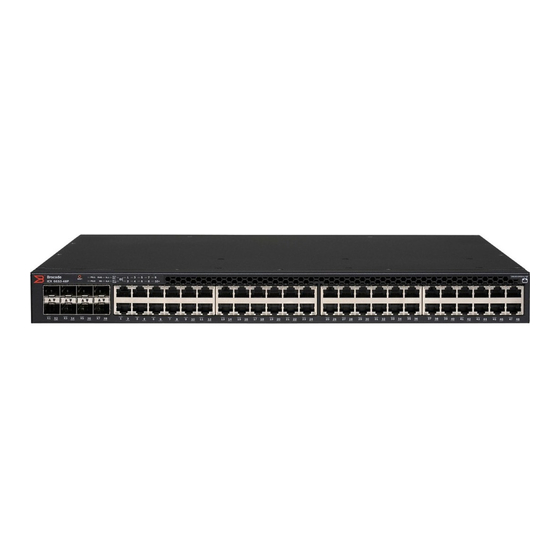
FIGURE 4 ICX 6610-48P rear panel with DC power supply FIGURE 5 ICX 6610-48 and ICX 6610-48P front panels FIGURE 6 ICX 6610-48P rear panel FIGURE 7 ICX 6610-24, ICX 6610-24F, and ICX 6610-48, rear panels Management interfaces Each ICX 6610 includes the following management interfaces: •... -
Page 15: Console Management Interface
Interface. When the reset button is pressed, the system resets and the software is reloaded. The reset button is located next to the PSU LED on both 24-port and 48-port models. Network interfaces for the ICX 6610 ICX 6610-24, ICX 6610-24, ICX 6610-48, and ICX 6610-48P contain the following interfaces: • 10/100/1000 Mbps ports with RJ-45 copper connectors •... -
Page 16: Slot Locations
Slot locations There are three slot locations on the ICX 6610: slots 3 and 1 on the front panel and slot 2 on the rear panel. FIGURE 10 Slot locations on the front panel of the 24-port model of the ICX 6610... -
Page 17: Slot Designations
10/100/1000 BASE-T ports All ICX 6610 copper devices provide 24 or 48 RJ-45 ports that operate at 10 Mbps or 100 Mbps half or full duplex, or at 1000 Mbps full duplex. In addition, ICX 6610 fiber models provide 24 SFP ports. -
Page 18: Specifying A Port Address
If the Up Link or Down Link LED is off, no connection exists, or the link is down. Port, system, and power status LEDs The ICX 6610 includes LEDs that indicate the status of device components. This section identifies and describes these LEDs. Brocade ICX 6610 Stackable Switch Hardware Installation Guide... - Page 19 Green (left side) 1000 Mbps Link-up Left LED off, right LED on or flashing 10/100 Mbps Link-up. Flashing indicates the port is transmitting and receiving user packets. Brocade ICX 6610 Stackable Switch Hardware Installation Guide 53-1003620-03...
- Page 20 (Stacking port status) 1-10+ Green Indicates the device stack ID. (Stack ID) FIGURE 15 Power status LED on 48-port models with AC power Power status LED with AC power supply installed Brocade ICX 6610 Stackable Switch Hardware Installation Guide 53-1003620-03...
-
Page 21: Fan Trays
The device has two fan tray receptacles on the rear panel. Each device ships with one fan tray installed. A secondary fan tray can be installed. Fan trays can be hot swapped. For instructions on installing and replacing a fan tray refer to Installing or replacing fan trays page 61 section. Brocade ICX 6610 Stackable Switch Hardware Installation Guide 53-1003620-03... -
Page 22: Power Supplies
LED status refer to Power status LEDs table in the section Port, system, and power status LEDs on page 18. FIGURE 18 ICX 6610 AC power supply receptacle on 48-port models AC power receptacle Brocade ICX 6610 Stackable Switch Hardware Installation Guide... -
Page 23: Poe And Poe+ Capacity On Ac And Dc Power Supplies
PoE and PoE+ capacity on AC and DC power supplies Several power options are available for the ICX 6610. All power supplies have the same overall form factor but differing power inlets. When a second power supply is installed in the same device for backup or increased capacity, it must be the same type. - Page 24 Brocade ICX 6610 Stackable Switch Hardware Installation Guide 53-1003620-03...
-
Page 25: Installing The Icx 6610 Switch
Before beginning the installation, see the precautions in “Power precautions.” Unpacking the device The ICX 6610 ships with all of the items in the following list. Verify the contents of your shipping container. If any items are missing, contact the place of purchase. -
Page 26: Installation Tasks
See the FastIron Ethernet Switch Security Configuration Guide. Installation precautions Follow all precautions when installing a device. General precautions DANGER Laser Radiation. Do Not View Directly with Optical Instruments. Class 1M Laser Products. Brocade ICX 6610 Stackable Switch Hardware Installation Guide 53-1003620-03... -
Page 27: Lifting Precautions
Disconnect the power cord from all power sources to completely remove power from the device. CAUTION Before plugging a cable into to any port, be sure to discharge the voltage stored on the cable by touching the electrical contacts to ground surface. Brocade ICX 6610 Stackable Switch Hardware Installation Guide 53-1003620-03... -
Page 28: Preparing The Installation Site
0 .5 - 550 m 50 µ 1500 MHz*km 0 .5 - 550 m 50 µ 2000 MHz*km 0 .5 - 550 m 1000Base-T Copper RJ-45 100 m 62.5 µ 100Base-FX 500 MHz*km 2 km Brocade ICX 6610 Stackable Switch Hardware Installation Guide 53-1003620-03... -
Page 29: Installation Location
Make sure the rack housing the device is adequately secured to prevent it from becoming unstable or falling over. Desktop installation Use the following steps to install the ICX 6610 on a desktop or other flat surface. Brocade ICX 6610 Stackable Switch Hardware Installation Guide... -
Page 30: Rack Mount Installation
Circuit overloading: Be sure that the supply circuit to the rack assembly is not overloaded. • Grounding: Rack-mounted equipment should be properly grounded. Be sure to check supply connections in addition to direct connections to the mains. Brocade ICX 6610 Stackable Switch Hardware Installation Guide 53-1003620-03... -
Page 31: Two-Post Rack Mount Installation
NOTE All ICX 6610 devices are shipped with a two-post rack mount kit to mount the switch into two-post Telco style racks only. If an ICX 6610 is to be installed into a standard four-post rack, please make sure that the correct rack mount kit is purchased. - Page 32 Installing the device FIGURE 21 Two-post rack mount kit for the Brocade ICX 6610 Bracket, front right Screw, 10-32 x 5/8 in., panhead Phillips Bracket, front left Retainer nut, 10-32, (for square-hole rack rails) Screw, 8-32 x 3/8 in., panhead Phillips...
- Page 33 Attach the mounting brackets to the sides of the device using the 8-32 x 3/8 in. screws. There are two sets of holes, labeled "A" or "B." Use the holes labeled "A" if you want the device to be flush with the rack rails. FIGURE 22 Attaching the brackets on an ICX 6610, flush-rail mounting Bracket 32 x 3/8 in.
- Page 34 Installing the device FIGURE 23 Attaching the brackets on an ICX 6610, mid-rail mounting Bracket 8-32 x 3/8 in. screws Position the switch in the cabinet, providing temporary support under the switch until the brackets are secured to the rack.
- Page 35 Attach the front right bracket to the rail rack using two 10-32 x 5/8 in. screws and the appropriate round or square retainer nuts. FIGURE 24 Installing the device, flush-rail mounting FIGURE 25 Installing the device, mid-rail mounting Brocade ICX 6610 Stackable Switch Hardware Installation Guide 53-1003620-03...
-
Page 36: Four-Post Rack Mount Installation
Kits for four-post rack mounting are not included in the shipping carton and must be ordered separately. NOTE Use the following procedure when installing the ICX 6610 in a four-post rack cabinet. For two-post cabinets, follow the procedures in the section Two-post rack mount installation on page 31. - Page 37 Retainer nut, 10-32, (for square-hole rack rails) Bracket extensions, up to 27 in. Retainer nut, 10-32, (for round-hole rack rails) Use the following steps to mount devices in a four-post rack. Brocade ICX 6610 Stackable Switch Hardware Installation Guide 53-1003620-03...
- Page 38 NOTE Do not use the hardware supplied in a two-post rack mounting kit to mount an ICX 6610 in a four-post rack. Mounting the device in a four-post rack requires additional hardware to prevent possible flexing and distortion of the four-post rack when a device is not properly installed.
- Page 39 FIGURE 28 Attaching bracket extensions Bracket 8-32 x 3/8 in. screws Position the switch in the cabinet, providing temporary support under the switch until the brackets on the device are secured to the rack. Brocade ICX 6610 Stackable Switch Hardware Installation Guide 53-1003620-03...
-
Page 40: Connecting Devices In A Traditional Stack
Connecting devices in a traditional stack The ICX 6610 can operate as a standalone device and also as a member of a traditional stack. A stack is a group of devices (Brocade stackable units and their connected stacking links) that are connected so that the stack is managed as a single entity. A traditional stack contains devices from only one model in a product family. -
Page 41: Stacking Configuration Requirements
FastIron Ethernet Switch Stacking Configuration Guide. Stacking cables Use 1 meter passive copper QSFP stacking cables or SFP+ fiber-optic cables to connect ICX 6610 devices in a traditional stack. The 40G-QSFP-SR4 optical transceiver is also supported. -
Page 42: Stacking Topologies
Linear (top) and ring (bottom) stacking topologies using one port per trunk • Ring stacking topology using both ports in each trunk FIGURE 31 Linear stacking topology using both ports in each trunk Brocade ICX 6610 Stackable Switch Hardware Installation Guide 53-1003620-03... - Page 43 Connecting devices in a traditional stack FIGURE 32 Linear and ring stacking topologies using one port per trunk Brocade ICX 6610 Stackable Switch Hardware Installation Guide 53-1003620-03...
-
Page 44: Connecting Devices In A Mixed Stack
Connecting devices in a mixed stack An ICX 6610 can operate as a standalone device or as a member of a mixed stack. A stack is a group of devices (Brocade stackable units and their connected stacking links) that are connected so that the stack is managed as a single entity. -
Page 45: Icx 6610 Stacking Ports And Trunks
Ports used to connect ICX 6610 devices in the backbone The ICX 6610 contains four ports in slot 2 on the rear panel that are dedicated stacking ports. They cannot be used as data ports, even when stacking is not enabled. There are two 40 Gbps ports and two 4 x 10 Gbps ports arranged in two rows. - Page 46 Ports used to connect ICX 6610 devices to ICX 6450 devices There are eight SFP+ ports in slot 3 on the front panel of an ICX 6610 device that are used to connect ICX 6610 devices to ICX 6450 devices in a mixed stack.
-
Page 47: Icx 6450 Stacking Ports And Trunks
Connecting devices in a mixed stack FIGURE 36 SFP+ ports on the front panel of the 48-port ICX 6610 model Slot 3: 10 Gbps SFP+ ports 1-8 Slot 1: 10/100/1000 Mbps ports ICX 6450 stacking ports and trunks The ICX 6450 contains four SFP+ ports in slot 2 on the front panel that can be used as uplink (data) ports or as stacking ports. The following figure shows the ports in slot 2. -
Page 48: Stacking Configuration Requirements
Before configuring the mixed stack, physically connect the devices using stacking cables. Secure-Setup utility To connect the SFP+ ports on the front of the ICX 6610 to ICX 6450 devices, configure the ports to 10 Gbps using the speed command as described in the Secure-Setup utility. -
Page 49: Stack Size
ICX 6450 peripheral devices. This is a single ring configuration in which the second ICX 6610 device is connected to the first ICX 6450 device, and the first ICX 6610 device is connected to the last ICX 6450 device. There is one substack that contains three peripheral devices. - Page 50 FIGURE 38 Topology 1: Single ring Topology 2: Dual ring In the following figure, two ICX 6610 devices form the backbone, and there are six ICX 6450 peripheral devices in two rings. This is a dual ring configuration. The first ICX 6610 device is connected to the last ICX 6450 device in the "vertical" ring. The backbone devices are also connected to the first and last ICX 6450 devices in the "horizontal"...
- Page 51 In the following figure, two ICX 6610 devices form the backbone, and there are six ICX 6450 peripheral devices in two substacks. Each substack contains three peripheral devices. One substack is connected to one ICX 6610 device to form a linear topology. The other substack is connected to each of the ICX 6610 devices to form a ring topology.
- Page 52 FIGURE 40 Topology 3: Linear and ring Topology 4: Ring with one backbone device In the following figure, one ICX 6610 device forms the backbone, and there are six ICX 6450 peripheral devices in a ring topology. One substack that contains all six peripheral devices.
-
Page 53: Connecting Icx 6610 Devices In The Backbone
ICX 6450 peripheral devices to each other. Both ports in each ICX 6450 trunk are used. One trunk (ports 1 and 2) in the middle ICX 6450 device is used for the upstream link to the ICX 6610. The other trunk (ports 3 and 4) in the middle ICX 6450 is used for the downstream link to the second ICX 6450. -
Page 54: Extended Distance Stacking
Attaching a PC or terminal FIGURE 43 Connecting a peripheral device to an ICX 6610 and to another peripheral device Extended distance stacking Extended distance stacking allows stacking of devices in a distributed network environment. You can form a stack of co-located devices or devices located over an extended distance to form a distributed stack. -
Page 55: Powering On The System
Power supplies for the Brocade ICX 6610 Each ICX 6610 ships by default with one alternating current (AC) power supply. A second power supply can be added. The ICX 6610 can also be ordered with direct current (DC) power supplies. -
Page 56: Installing An Ac Power Supply
Holding the power supply level, guide it into the carrier rails on each side and gently push it all the way into the slot, ensuring that it firmly engages with the connector. Brocade ICX 6610 Stackable Switch Hardware Installation Guide 53-1003620-03... -
Page 57: Installing A Dc Power Supply
For the DC input circuit to the system, make sure there is a 20 Amp circuit breaker, minimum 60 VDC, double pole, on the input terminal block to the power supply. The input wiring for connection to the product should be copper wire, 12 AWG, marked VW-1, and rated minimum 90°C. Brocade ICX 6610 Stackable Switch Hardware Installation Guide 53-1003620-03... - Page 58 Brocade recommends using an ESD wrist strap during installation. DANGER For safety reasons, the ESD wrist strap should contain a series 1 megaohm resistor. Ensure the power on the DC power supply is switched off. Brocade ICX 6610 Stackable Switch Hardware Installation Guide 53-1003620-03...
- Page 59 Before opening the package that contains the DC power supply, touch the bag to the switch casing to discharge any potential static electricity. Remove the DC power supply from the anti-static shielded bag. Brocade ICX 6610 Stackable Switch Hardware Installation Guide 53-1003620-03...
- Page 60 FIGURE 47 DC power supply wiring assembly 1 Wire tightening screws 2 DC power source wires 3 Earth ground wire 4 Assembly screws Use the wire tightening screws to secure the wires. Brocade ICX 6610 Stackable Switch Hardware Installation Guide 53-1003620-03...
-
Page 61: Installing Or Replacing Fan Trays
"E", or an orange arrow with an "I." You can run the device with one or two fan trays installed. If you install a second power supply, it is recommended that you install a second fan tray. Brocade ICX 6610 Stackable Switch Hardware Installation Guide 53-1003620-03... -
Page 62: Danger
Installing or replacing fan trays FIGURE 49 Installing a fan tray on an ICX 6610 (1000W) Perform the following steps to install a fan tray in the switch. NOTE It is recommended that you wear an ESD wrist strap during installation. -
Page 63: Checking Network Devices And Testing Connectivity
Read Only - Allows access to the Privileged EXEC mode and CONFIG mode but only with read access. Setting passwords Perform the following steps to set passwords. At the opening CLI prompt, enter the following command to change to the Privileged level of the EXEC mode: device> enable Brocade ICX 6610 Stackable Switch Hardware Installation Guide 53-1003620-03... -
Page 64: Recovering From A Lost Password
To enter a prefix number for a network mask, enter a forward slash (/) and the number of bits in the mask immediately after the IP address. For example, enter 10.157.22.99 /24 for an IP address that has a network mask with 24 significant ("mask") bits. Brocade ICX 6610 Stackable Switch Hardware Installation Guide 53-1003620-03... -
Page 65: Devices Running Layer 2 Software
Devices running Layer 3 software Before attaching equipment to an ICX 6610, you must assign an interface IP address to the subnet on which the device will be located. You must use the serial connection to assign the first IP address. For subsequent addresses, you also can use the CLI through Telnet or SSH. - Page 66 Once you configure a virtual routing interface on a VLAN, you cannot configure Layer 3 interface parameters on individual ports in the VLAN. Instead, you must configure the parameters on the virtual routing interface itself. Brocade ICX 6610 Stackable Switch Hardware Installation Guide 53-1003620-03...
- Page 67 Enter commands similar to the following to add a virtual interface to a VLAN and configure an IP address on the interface. device(config)# vlan 2 name IP-Subnet_10.1.2.1/24 device(config-vlan-2)# untag 1/1/1 to 1/1/4 device(config-vlan-2)# router-interface ve1 device(config-vlan-2)# interface ve1 device(config-vif-1)# ip address 10.1.2.1/24 Brocade ICX 6610 Stackable Switch Hardware Installation Guide 53-1003620-03...
-
Page 68: Connecting Network Devices
1000Base-T ports. In this case, a straight-through cable may work just as well as a crossover cable. For more information about this feature, refer to the FastIron Ethernet Switch Security Configuration Guide. Brocade ICX 6610 Stackable Switch Hardware Installation Guide 53-1003620-03... -
Page 69: Connecting To Workstations, Servers, Or Routers
Fiber cabling is required for direct attachment to Gigabit NICs or switches and routers through fiber ports. Refer to the section Connecting a network device to a fiber port on page 70. Brocade ICX 6610 Stackable Switch Hardware Installation Guide 53-1003620-03... -
Page 70: Connecting A Network Device To A Fiber Port
10 km 1000Base-LHA 70 km 1000Base-LHB 120 km 1000Base-CWDM 80 km 1000Base-BXU 10 km 1000Base-BXD 10 km 100Base-FX 2 km 100Base-FX-IR 15 km 100Base-FX-LR 40 km 10GSFPP-SR 300 m 10GSFPP-LR 10 km Brocade ICX 6610 Stackable Switch Hardware Installation Guide 53-1003620-03... -
Page 71: Installing A Transceiver
Remove the protective covering from the fiber-optic port connectors and store the covering for future use. NOTE Before cabling a fiber-optic transceiver, Brocade strongly recommends cleaning the cable connectors and the port connectors. For more information, refer to Cleaning the fiber-optic connectors on page 72. Brocade ICX 6610 Stackable Switch Hardware Installation Guide 53-1003620-03... -
Page 72: Testing Connectivity
Test for connectivity by observing the LEDs related to network connection. Pinging an IP address To verify that an ICX 6610 can reach another device through the network, enter a command similar to the following at any level of the CLI. - Page 73 You can do the following: • Verify that the connection to the other network device has been properly made. Also, make certain that the other network device is powered on and operating correctly. Brocade ICX 6610 Stackable Switch Hardware Installation Guide 53-1003620-03...
- Page 74 You can do Speed the following: • Check the Link LED to make sure the link is still established with the remote port. If not, take the actions described in the Meaning or Brocade ICX 6610 Stackable Switch Hardware Installation Guide 53-1003620-03...
-
Page 75: Tracing A Route
This method of cable analysis is referred to as Time Domain Reflectometry (TDR). By examining the reflection, the Brocade device can detect and report cable statistics such as local and remote link pair, cable length, and link status. Brocade ICX 6610 Stackable Switch Hardware Installation Guide 53-1003620-03... -
Page 76: Viewing The Results Of The Cable Analysis
--------- ----- ---------- ----------- ----------- ----------- ----- ------- ----- ------ ---------- UNKWN Pair A <=3 M Open Pair B <=3 M Open Pair C <=3 M Open Pair D <=3 M Open Brocade ICX 6610 Stackable Switch Hardware Installation Guide 53-1003620-03... - Page 77 Pair D Pair 4 (brown) The following figure illustrates the T568A pin/pair assignment. FIGURE 53 T568A pin/pair assignment The following table describes the fields shown in the show cable-diagnostics port command output. Brocade ICX 6610 Stackable Switch Hardware Installation Guide 53-1003620-03...
- Page 78 Terminated: The link is up. • Shorted: A short is detected in the cable. • Open: An opening is detected in the cable. • ImpedMis: The impedance is mismatched. • Failed: The TDR test failed. Brocade ICX 6610 Stackable Switch Hardware Installation Guide 53-1003620-03...
-
Page 79: Managing The Icx 6610 Hardware
Fan 1 Air Flow Direction: Front to Back MAC 1 Temperature Readings: Current temperature : 32.5 deg-C MAC 2 Temperature Readings: Current temperature : 46.5 deg-C CPU Temperature Readings: Current temperature : 39.5 deg-C Brocade ICX 6610 Stackable Switch Hardware Installation Guide 53-1003620-03... -
Page 80: Displaying Syslog Messages For Temperature
The stack unit 1 chassis info: Power supply 1 not present Power supply 2 (AC - Regular) present, status ok Model Number: 23-0000144-01 Serial Number: Firmware Ver: Brocade ICX 6610 Stackable Switch Hardware Installation Guide 53-1003620-03... - Page 81 D Temperature Readings: Current temperature : 27.0 deg-C stacking card Temperature Readings: Current temperature : 61.5 deg-C Warning level..: 84.0 deg-C Shutdown level..: 87.0 deg-C Boot Prom MAC : 748e.f8dc.952a Management MAC: 748e.f8dc.952a Brocade ICX 6610 Stackable Switch Hardware Installation Guide 53-1003620-03...
-
Page 82: Changing The Temperature Poll Time
Syntax: show cpu Hardware maintenance schedule ICX 6610 switch hardware components require minimal maintenance. Brocade recommends cleaning the fiber-optic connectors on a fiber-optic port and the connected fiber cable each time you disconnect the cable. Brocade ICX 6610 Stackable Switch Hardware Installation Guide... -
Page 83: Removing A Copper Or Fiber-Optic Module
Removing a copper or fiber-optic module You can remove a copper or fiber SFP transceiver from a slot while the ICX 6610 is powered on and running. While removing a copper or fiber-optic module, be sure to wear an ESD wrist strap with a plug that can be inserted in the ESD connector on the ICX 6610. -
Page 84: Cabling A Fiber-Optic Module
For instructions on cabling a fiber-optic module, refer to the section Cabling a fiber-optic transceiver on page 71. Cleaning the fiber-optic connectors For instructions on cleaning a fiber-optic module, refer to the section Cleaning the fiber-optic connectors on page 72. Brocade ICX 6610 Stackable Switch Hardware Installation Guide 53-1003620-03... -
Page 85: Brocade Icx 6610 Switch Technical Specifications
Brocade ICX 6610 Switch Technical Specifications This document highlights the features and specifications for the Brocade ICX 6610 switch. System specifications System component Description Enclosure 1U, stackable, standard 19-inch rack compliant or on a flat surface Power inlet Power supplies... -
Page 86: Weight And Physical Dimensions
RPS16-E 1000 W 100 - 240 VAC 50/60 Hz 11.8 A - 4.9 A Line & Neutral 35 A peak for <10 Fused ms, 10 ms - 150 RPS16-I Brocade ICX 6610 Stackable Switch Hardware Installation Guide 53-1003620-03... -
Page 87: Power Consumption (Maximum Configuration)
RJ-45 ports Mbps ICX 6610-24F 100/1000 Mbps SFP ports 1/10 GbE Dual-mode SFP/SFP+ ports 40 Gbps QSFP stacking ports ICX 6610-24P 10/100/1000 24 (one power Maximum PoE Class 3 ports (PoE+) supply) Brocade ICX 6610 Stackable Switch Hardware Installation Guide 53-1003620-03... -
Page 88: Serial Port Specifications (Pinout Rj-45)
EN 55024 (CE mark) (Immunity) for Information Technology Equipment • ICES-003 (Canada) (Class A) • AS/NZ 55022 (Australia) (Class A) • VCCI (Japan) (Class A) • EN 61000-3-2 • EN 61000-3-3 • EN 61000-6-1 Brocade ICX 6610 Stackable Switch Hardware Installation Guide 53-1003620-03... -
Page 89: Regulatory Compliance (Safety)
30/2011/TT-BCT - Vietnam circular • SJ/T 11363-2006 Requirements for Concentration Limits for Certain Hazardous Substances in EIPs (China) • SJ/T 11364-2006 Marking for the Control of Pollution Caused by EIPs (China) • NEBS-compliant Brocade ICX 6610 Stackable Switch Hardware Installation Guide 53-1003620-03... - Page 90 Brocade ICX 6610 Stackable Switch Hardware Installation Guide 53-1003620-03...
-
Page 91: Troubleshooting
• Check connections between the be disconnected. switch, the power cord, and the wall outlet. • Contact Technical Support. Power LED is Yellow Internal power supply has failed. Contact Technical Support. Brocade ICX 6610 Stackable Switch Hardware Installation Guide 53-1003620-03... -
Page 92: Power And Cooling Problems
IP address. Also be sure the port through which you are connecting to the switch has not been disabled. If it has not been disabled, then check the network cabling that runs between your remote location and the switch. Brocade ICX 6610 Stackable Switch Hardware Installation Guide 53-1003620-03... -
Page 93: Regulatory Statements
This Class A digital apparatus meets all requirements of the Canadian Interference-Causing Equipment Regulations, ICES-003 Class A. Cet appareil numérique de la classe A est conforme à la norme NMB-003 du Canada. Brocade ICX 6610 Stackable Switch Hardware Installation Guide 53-1003620-03... -
Page 94: China Cc Statement
Europe and Australia (CISPR 22 Class A Warning) This is a Class A product. In a domestic environment this product may cause radio interference in which case the user may be required to take adequate measures. Brocade ICX 6610 Stackable Switch Hardware Installation Guide 53-1003620-03... -
Page 95: Fcc Warning (Us Only)
This is a Class A product based on the standard of the Voluntary Control Council for Interference by Information Technology Equipment (VCCI). If this equipment is used in a domestic environment, radio disturbance might arise. When such trouble occurs, the user might be required to take corrective actions. Brocade ICX 6610 Stackable Switch Hardware Installation Guide 53-1003620-03... - Page 96 Brocade ICX 6610 Stackable Switch Hardware Installation Guide 53-1003620-03...
-
Page 97: Cautions And Danger Notices
Veillez à ce que le sens de circulation de l'air du bloc d'alimentation corresponde à celui du tiroir de ventilation installé. Les blocs d'alimentation et les tiroirs de ventilation sont étiquetés d'une flèche verte avec un "E " ou d'une flèche orange avec un " I ". Brocade ICX 6610 Stackable Switch Hardware Installation Guide 53-1003620-03... -
Page 98: Electrical Cautions
Une zone à accès réglementé est une zone dont l'accès n'est possible qu'au personnel de service utilisant un verrou, une clé ou un outil spécial, ou d'autres moyens de sécurité, et qui est contrôlée par les autorités responsables du site. Brocade ICX 6610 Stackable Switch Hardware Installation Guide 53-1003620-03... - Page 99 Avant de brancher un câble à un port, assurez-vous de décharger la tension du câble en reliant les contacts électriques à la terre. PRECAUCIÓN Antes de conectar un cable en cualquier puerto, asegúrese de descargar la tensión acumulada en el cable tocando la superficie de conexión a tierra con los contactos eléctricos. Brocade ICX 6610 Stackable Switch Hardware Installation Guide 53-1003620-03...
- Page 100 Para un sistema de CC, usar alambre de puesta a tierra de por lo menos 12 AWG (American Wire Gauge). El cable de tierra debe ser conectada a enchufe DC el otro extremo se conecta a la tierra del edificio. Brocade ICX 6610 Stackable Switch Hardware Installation Guide 53-1003620-03...
-
Page 101: Danger Notices
Falls für die Installation ein anderes Stromkabel erforderlich ist (wenn das mit dem Gerät gelieferte Kabel nicht passt), müssen Sie sicherstellen, dass Sie ein Stromkabel mit dem Siegel einer Sicherheitsbehörde verwenden, die für die Zertifizierung von Brocade ICX 6610 Stackable Switch Hardware Installation Guide 53-1003620-03... - Page 102 Das eingeschaltete Gerät darf nicht geöffnet werden, da andernfalls das Risiko eines Stromschlags mit Hochspannung besteht. DANGER Afin d'éviter tout choc électrique, n'ouvrez pas l'appareil lorsqu'il est sous tension. PELIGRO Para evitar una descarga de alto voltaje, no abra el dispositivo mientras esté encendido. Brocade ICX 6610 Stackable Switch Hardware Installation Guide 53-1003620-03...
- Page 103 Rayonnement de laser. Ne regardez pas directement avec des instruments optiques. Produits de laser de classe 1M. PELIGRO Radiacion de Laser. No vea directamente con Instrumentos Opticos. Clase 1M de Productos de Laser. 警告 レーザ放射 光学器具で直接ビームを見ないこと クラス1 M レーザ製品 Brocade ICX 6610 Stackable Switch Hardware Installation Guide 53-1003620-03...
Need help?
Do you have a question about the ICX 6610 and is the answer not in the manual?
Questions and answers