Brocade Communications Systems ICX 6430 Installation Manual
Stackable switches
Hide thumbs
Also See for ICX 6430:
- Hardware installation manual (116 pages) ,
- Datasheet (12 pages) ,
- Diagnostic manual (220 pages)

Related Manuals for Brocade Communications Systems ICX 6430


Summary of Contents for Brocade Communications Systems ICX 6430
- Page 1 53-1002738-02 ® 24 June 2013 Brocade ICX 6430 and ICX 6450 Stackable Switches Hardware Installation Guide...
- Page 2 Export of technical data contained in this document may require an export license from the United States government. The authors and Brocade Communications Systems, Inc. shall have no liability or responsibility to any person or entity with respect to any loss, cost, liability, or damages arising from the information contained in this book or the computer programs that accompany it.
-
Page 3: Table Of Contents
ICX 6430 models ........ - Page 4 Powering on the system ........51 Brocade ICX 6430 and ICX 6450 Stackable Switches Hardware Installation Guide...
- Page 5 Cabling a fiber-optic transceiver ......75 Cleaning the fiber-optic connectors..... . 76 Brocade ICX 6430 and ICX 6450 Stackable Switches Hardware Installation Guide 53-1002738-02...
- Page 6 Danger notices ......... .95 Brocade ICX 6430 and ICX 6450 Stackable Switches Hardware Installation Guide...
-
Page 7: About This Document
• Chapter 1, “ICX 6430 and ICX 6450 Overview,” provides a list of the hardware features supported on the Brocade ICX 6430 and ICX 6450 devices, and a look at the appearance of the devices. • Chapter 2, “ICX 6430 and ICX 6450 Installation,”... -
Page 8: Supported Software
Document conventions This section describes text formatting conventions and important notice formats used in this document. Text formatting The narrative-text formatting conventions that are used are as follows: viii Brocade ICX 6430 and ICX 6450 Stackable Switches Hardware Installation Guide 53-1002738-02... -
Page 9: Command Syntax Conventions
This book describes how to perform configuration tasks using the command line interface (CLI), but does not describe the commands in detail. For complete descriptions of commands for Brocade ICX 6430 and ICX 6450 devices, see the FastIron Ethernet Switch Stacking Configuration Guide. Notes, cautions, and warnings The following notices and statements are used in this manual. -
Page 10: Related Publications
However, if you find an error or an omission, or you think that a topic needs further development, we want to hear from you. Forward your feedback to: Brocade ICX 6430 and ICX 6450 Stackable Switches Hardware Installation Guide 53-1002738-02... - Page 11 Provide the title and version number of the document and as much detail as possible about your comment, including the topic heading and page number and your suggestions for improvement. Brocade ICX 6430 and ICX 6450 Stackable Switches Hardware Installation Guide 53-1002738-02...
- Page 12 Brocade ICX 6430 and ICX 6450 Stackable Switches Hardware Installation Guide 53-1002738-02...
-
Page 13: Chapter 1 Icx 6430 And Icx 6450 Overview
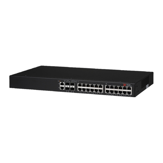
ICX 6430-24 — 24 10/100/1000 Mbps copper ports and 4 1-Gbps SFP fiber uplink and stacking ports • ICX 6430-24P — 24 10/100/1000 Mbps PoE+ copper ports and 4 1-Gbps SFP fiber uplink and stacking ports. • ICX 6430-48 — 48 10/100/1000 Mbps copper ports and 4 1-Gbps SFP fiber uplink and stacking ports •... -
Page 14: Icx 6450 Models
ICX 6450-48P — 48 10/100/1000 Mbps PoE+ copper ports and 4 ports with 1 or 10 Gbps SFP+ fiber uplink and stacking ports NOTE The ICX 6450-24P and ICX 6450-48P devices support up to 802.3 at PoE+. Brocade ICX 6430 and ICX 6450 Stackable Switches Hardware Installation Guide 53-1002738-02... - Page 15 ICX 6450-48 front panel FIGURE 9 ICX 6450-48P front panel FIGURE 10 ICX 6450-48P rear panel FIGURE 11 ICX 6450-24P rear panel FIGURE 12 ICX 6450-24 and ICX 6450-48 rear panels Brocade ICX 6430 and ICX 6450 Stackable Switches Hardware Installation Guide 53-1002738-02...
-
Page 16: Network And Management Interfaces
Network and management interfaces Network and management interfaces Each ICX 6430 and ICX 6450 includes the following management interfaces, and a system reset button on the front panel of the device: • Console management interface (RJ45 serial port) • Out-of-band management interface (RJ45 port) •... -
Page 17: Out-Of-Band Management Interface
10/100/1000 BASE-T ports All ICX 6430 and ICX 6450 devices provide 24 or 48 RJ45 ports that operate at 10 Mbps or 100 Mbps half or full duplex, or at 1000 Mbps full duplex. Because all ports support automatic MDI or MDI-X operation, you can use straight-through cables for all network connections to PCs, servers, or other devices or hubs. -
Page 18: Specifying A Port Address
These ports reside on Slot 2 of the stackable switch and can be used as uplink (data) ports or stacking ports. The ICX 6430 contains SFP ports that support 1 Gbps port speeds but do not support 10 Gbps port speeds. The ICX 6450 contains SFP+ ports that support 1 Gbps or 10 Gbps port speeds. -
Page 19: Port, System, And Power Status Leds
Port, system, and power status LEDs • stack unit—Specifies the stack unit ID. For the ICX 6430, range is from 1 to 4. For the ICX 6450, range is from 1 to 8. • slot—Specifies the slot number. Stacking ports are in slot 2. - Page 20 Port, system, and power status LEDs Table 3 lists the port status LEDs on the ICX 6450 and ICX 6430 devices and their corresponding conditions and status. TABLE 3 Port status LEDs Condition Status Ethernet On/Flashing Green The port has established a valid link at 10, 100 or 1000 Mbps.
- Page 21 Indicates the switch ID in the stack. (Switch ID in the For ICX 6430 devices, 1 - 4 indicates the switch ID in the stack. stack) For ICX 6450 devices, 1 - 8 indicates the switch ID in the stack.
-
Page 22: Power Supplies
Power status LED on the ICX 6430-48 and ICX 6430-48P models NOTE The location of the power status LED on the front panel of the ICX 6430-48 and ICX 6430-48P devices is the same on the ICX 6430-24P device, ICX 6450-24 device, ICX 6450-24P device, and the ICX 6450-48 device. -
Page 23: Power Supply Usage
ICX 6430-48 power supply connectors AC power supply socket External power supply (EPS) connector Table 6 shows the number of EPS connectors supported for the different ICX 6430 and ICX 6450 models. TABLE 6 EPS connectors on the ICX 6430 and ICX 6450 models... - Page 24 ICX 6450-24 44.4 Watts ICX 6450-24P 481.3 Watts 24 PoE ports 12 PoE+ ports ICX 6450-48 65.6 Watts ICX 6450-48P 912.4 Watts 48 PoE ports 24 PoE+ ports Brocade ICX 6430 and ICX 6450 Stackable Switches Hardware Installation Guide 53-1002738-02...
-
Page 25: Icx 6430 And Icx 6450 Installation
This chapter contains the following sections: • Items included with the ICX 6430 and ICX 6450 devices ....13 • Configuration requirements ........14 •... -
Page 26: Configuration Requirements
Read Me First document Configuration requirements To manage the ICX 6430 or ICX 6450, you need a management station, such as a PC running a terminal emulation application, for serial connection to the device. Use the serial connection to perform basic configuration tasks, including assigning an IP address and network mask to the system. -
Page 27: Lifting Precautions
Power precautions CAUTION Use a separate branch circuit for each AC power cord, which provides redundancy in case one of the circuits fails. Brocade ICX 6430 and ICX 6450 Stackable Switches Hardware Installation Guide 53-1002738-02... -
Page 28: Preparing The Installation Site
Allow at least 7.62 cm (3 in.) of space at the front and back of the device for the twisted-pair, fiber-optic, and power cabling. • The site should be accessible for installing, cabling and maintaining the devices. Brocade ICX 6430 and ICX 6450 Stackable Switches Hardware Installation Guide 53-1002738-02... -
Page 29: Rack-Mount Installation Considerations
Desktop installation Complete the following steps to install the ICX 6430 or ICX 6450 device on a desktop or other flat surface. Brocade ICX 6430 and ICX 6450 Stackable Switches Hardware Installation Guide... -
Page 30: Rack Mount Installation
2. Using a Phillips screwdriver, attach the mounting brackets to the sides of the device using six sink-head screws, as illustrated in Figure 23. Brocade ICX 6430 and ICX 6450 Stackable Switches Hardware Installation Guide 53-1002738-02... - Page 31 5. Using a Phillips screwdriver, mount the device in a two-post rack using four rack-mounting screws, as illustrated in Figure NOTE The ICX 6430 and ICX 6450 devices must be installed on 2-post racks only. The devices cannot be installed on 4-post racks. FIGURE 24 Installing the device in a two-post rack...
-
Page 32: Wall Mount Installation
You need a #2 Phillips screwdriver, a hammer, and a drill for wall mount installation. Mounting the device to a wall is only applicable to ICX 6430-24, ICX 6430-24P, ICX 6450-24, and ICX 6450-24P devices. Brocade recommends that you wall mount the device with the port side down. - Page 33 4. Hammer two wall mount anchors into the holes on the wall, as illustrated in Figure 5. Use the two wall mount screws to fasten the device to the wall mount anchors, as illustrated in Figure Brocade ICX 6430 and ICX 6450 Stackable Switches Hardware Installation Guide 53-1002738-02...
- Page 34 Installing the device FIGURE 26 Wall mounting the ICX 6430-24P device Drilled holes Wall mount anchors Wall mount screws Brocade ICX 6430 and ICX 6450 Stackable Switches Hardware Installation Guide 53-1002738-02...
-
Page 35: Connecting Devices In A Traditional Stack
ICX 6450 devices. A traditional stack cannot contain both ICX 6430 devices and ICX 6450 devices. Stacking ports and trunks There are four SFP ports (ICX 6430) or four SFP+ ports (ICX 6450) on the front panels that can be used as uplink (data) ports or as stacking ports. Figure 27 shows the ports in slot 2;... -
Page 36: Stacking Configuration Requirements
The copper cable lengths for 10-Gbps ports are 1 meter, 3 meters, and 5 meters. Stack size A traditional stack can contain a maximum of eight ICX 6450 devices or four ICX 6430 devices. A traditional stack cannot contain both ICX 6430 and ICX 6450 devices. - Page 37 Connecting devices in a traditional stack FIGURE 28 Linear and ring stacking topologies using one port per trunk FIGURE 29 Linear stacking topology using both ports in each trunk Brocade ICX 6430 and ICX 6450 Stackable Switches Hardware Installation Guide 53-1002738-02...
-
Page 38: Connecting Devices In A Mixed Stack
ICX 6450 to ICX 6450 ICX 6610 stacking ports and trunks This section discusses the ports you can use to connect ICX 6610 devices in the backbone and to ICX 6450 devices. Brocade ICX 6430 and ICX 6450 Stackable Switches Hardware Installation Guide 53-1002738-02... - Page 39 Port 2 Port 2 to Port 1 • If you connect both ports in a trunk, both ports must connect to both ports of one trunk on another device. Brocade ICX 6430 and ICX 6450 Stackable Switches Hardware Installation Guide 53-1002738-02...
-
Page 40: Icx 6450 Stacking Ports And Trunks
(data) ports or as stacking ports. Figure 27 shows the ports in slot 2; the top row consists of ports 1 and 3, and the bottom row consists of ports 2 and 4. Brocade ICX 6430 and ICX 6450 Stackable Switches Hardware Installation Guide 53-1002738-02... - Page 41 NOTE If you use the Secure Setup utility to set up a mixed stack, the stacking units (ICX 6610 devices and ICX 6450 devices) are automatically trunked. Brocade ICX 6430 and ICX 6450 Stackable Switches Hardware Installation Guide 53-1002738-02...
-
Page 42: Stacking Configuration Requirements
Peripheral devices can form one or more substacks. A substack is a topology that is formed by ICX 6450 devices. If ICX 6450 devices are separated by an ICX 6610 device, the ICX 6450 devices belong to different substacks. Brocade ICX 6430 and ICX 6450 Stackable Switches Hardware Installation Guide 53-1002738-02... -
Page 43: Stacking Topologies
The first ICX 6610 device is connected to the last ICX 6450 device in the “vertical” ring. The backbone devices are also connected to the first and last ICX 6450 devices in the “horizontal” ring. There are two substacks, each containing three peripheral devices. Brocade ICX 6430 and ICX 6450 Stackable Switches Hardware Installation Guide 53-1002738-02... - Page 44 ICX 6610 device either by design or because the link is broken. This is still a valid topology. FIGURE 37 Topology 3: linear and ring ICX 6610 ICX 6610 ICX 6450 ICX 6450 ICX 6450 ICX 6450 ICX 6450 ICX 6450 Brocade ICX 6430 and ICX 6450 Stackable Switches Hardware Installation Guide 53-1002738-02...
-
Page 45: Connecting Icx 6610 Devices In The Backbone
(ports 1 and 2) in trunk 0 of each ICX 6610 device. Ports 1 and 2 in the top device connect to ports 1 and 2 in the bottom device, respectively. Brocade ICX 6430 and ICX 6450 Stackable Switches Hardware Installation Guide 53-1002738-02... -
Page 46: Connecting A Peripheral Device To An Icx 6610 And To Another Peripheral Device
1/3/1 or 3/2/1. FIGURE 40 Connecting a peripheral device to an ICX 6610 and to another peripheral device ICX 6610 ICX 6450 ICX 6450 Brocade ICX 6430 and ICX 6450 Stackable Switches Hardware Installation Guide 53-1002738-02... -
Page 47: Extended Distance Stacking
2. Attach the AC power cord to the AC connector on the rear panel. 3. Insert the power cord plug into a 100V-240V outlet. NOTE To turn the system off, simply unplug the power cord or cords. Brocade ICX 6430 and ICX 6450 Stackable Switches Hardware Installation Guide 53-1002738-02... - Page 48 Powering on the system Brocade ICX 6430 and ICX 6450 Stackable Switches Hardware Installation Guide 53-1002738-02...
-
Page 49: Icx 6400-Eps1500 External Power Supply
6400-EPS1500 external power supply can be used as a backup power source to a device when any of the three ports are connected to an ICX 6430 or ICX 6450 device. Proprietary DC cables are used to connect any of the three EPS ports of the ICX 6400-EPS1500 to the rear EPS port of an ICX 6430 or ICX 6450 device. -
Page 50: Features And Benefits
EPS connectors must be connected to the ICX 6400-EPS1500. If you increase the maximum number of PoE or PoE+ ports that can be supported in each ICX 6430 or ICX 6450 device, and if the internal power supply fails, the ICX 6400-EPS1500 cannot guarantee the devices are protected by the backup power source. -
Page 51: Front And Rear Panels
• If an ICX 6430 or ICX 6450 device is not connected to an EPS port, the power will not come up. • Power supplies are hot swappable. The device can be running while the ICX 6430 or ICX 6450 units are connected to the ICX 6400-EPS1500. -
Page 52: Leds
The ICX 6400-EPS1500 ships with all of the following items included in your shipping container. Verify the contents of your shipping container. If any items are missing, contact the place of purchase. Brocade ICX 6430 and ICX 6450 Stackable Switches Hardware Installation Guide 53-1002738-02... -
Page 53: General Requirements
Verify that the device is working properly by plugging it into “Verifying proper operation” on page 52 a power source and verifying that it passes the self test. Brocade ICX 6430 and ICX 6450 Stackable Switches Hardware Installation Guide 53-1002738-02... -
Page 54: Installation Precautions
DANGER Mount the devices you install in a rack or cabinet as low as possible. Place the heaviest device at the bottom and progressively place lighter devices above. Brocade ICX 6430 and ICX 6450 Stackable Switches Hardware Installation Guide 53-1002738-02... -
Page 55: Power Precautions
2.44 m (8 ft) of each device, and is powered from an independent circuit breaker. • As with any electrical equipment, a filter or surge suppressor is recommended. Brocade ICX 6430 and ICX 6450 Stackable Switches Hardware Installation Guide 53-1002738-02... -
Page 56: Rack-Mount Installation Considerations
2. Set the external power supply on a flat surface near an AC power source, making sure there are at least 5.08 cm (2 in.) of space on all sides for proper airflow. Brocade ICX 6430 and ICX 6450 Stackable Switches Hardware Installation Guide 53-1002738-02... -
Page 57: Mounting An External Power Supply In A Rack
Figure FIGURE 45 Attaching the mounting brackets for the ICX 6400-EPS1500 3. Mount the external power supply in a rack using four rack-mounting screws, as illustrated in Figure Brocade ICX 6430 and ICX 6450 Stackable Switches Hardware Installation Guide 53-1002738-02... -
Page 58: Assembling The Wire Saddle For The Eps Cord
Assemble the wire saddle on both ends of the EPS cord. Complete the following steps to assemble the wire saddle for the EPS cord. Brocade ICX 6430 and ICX 6450 Stackable Switches Hardware Installation Guide 53-1002738-02... - Page 59 1. Using a Phillips screwdriver, remove the two screws on the EPS faceplate of the external power receptacle, as illustrated in Figure FIGURE 47 Removing the EPS faceplate on the ICX 6430 or ICX 6450 device Screws and faceplate Brocade ICX 6430 and ICX 6450 Stackable Switches Hardware Installation Guide 53-1002738-02...
- Page 60 Installing the device 2. Clip the cable tie onto the wire saddle, as illustrated in Figure FIGURE 48 Assembling the cable tie and wire saddle Cable tie Wire saddle Brocade ICX 6430 and ICX 6450 Stackable Switches Hardware Installation Guide 53-1002738-02...
- Page 61 FIGURE 49 Complete assembly of cable tie and wire saddle Wire saddle 4. Open the wire saddle hook and plug the EPS cord into the external power receptacle. Brocade ICX 6430 and ICX 6450 Stackable Switches Hardware Installation Guide 53-1002738-02...
-
Page 62: Connecting Devices To The External Power Supply
Refer to Figure 4. Connect one end of the AC cord to the AC receptacle on the external power supply, and the other end to a grounded power outlet. Brocade ICX 6430 and ICX 6450 Stackable Switches Hardware Installation Guide 53-1002738-02... -
Page 63: Powering On The System
Powering on the system After you complete the physical installation, you can power on the system. NOTE The socket should be installed near the equipment and should be easily accessible. Brocade ICX 6430 and ICX 6450 Stackable Switches Hardware Installation Guide 53-1002738-02... -
Page 64: Verifying Proper Operation
LEDs for linked ports will again come on. For more details on specific LED conditions after system start-up, refer to, “LEDs” on page 40. Brocade ICX 6430 and ICX 6450 Stackable Switches Hardware Installation Guide 53-1002738-02... -
Page 65: Configuring An Icx 6430 Or Icx 6450 Device
Continue configuring the device using the CLI. You can FastIron Ethernet Switch Administration also use Brocade Network Advisor to manage the device. Guide Secure access to the device. FastIron Ethernet Switch Administration Guide Brocade ICX 6430 and ICX 6450 Stackable Switches Hardware Installation Guide 53-1002738-02... -
Page 66: Pc Or Terminal Attachment
Refer to the FastIron Ethernet Switch Administration Guide. NOTE You can assign passwords using Brocade Network Advisor if an enable password for a Super User has been configured on the device. Brocade ICX 6430 and ICX 6450 Stackable Switches Hardware Installation Guide 53-1002738-02... -
Page 67: Assigning Passwords
You must set the Super User password before you can set other types of passwords. 4. Enter the following commands to set the port configuration and read-only passwords: Brocade (config)# enable port-config-password john Brocade (config)# enable read-only-password sam Brocade ICX 6430 and ICX 6450 Stackable Switches Hardware Installation Guide 53-1002738-02... -
Page 68: Recovering From A Lost Password
By default, the CLI displays network masks in classical IP address format (for example, 255.255.255.0). You can change the display to the prefix format. Refer to the FastIron Ethernet Switch Administration Guide. Brocade ICX 6430 and ICX 6450 Stackable Switches Hardware Installation Guide 53-1002738-02... -
Page 69: Devices Running Layer 2 Software
Devices running Layer 2 software NOTE The ICX 6430 device supports only switch code. The ICX 6450 device supports both switch and router code. Use the following procedure to configure an IP address on a device running Layer 2 software. - Page 70 Once you configure a virtual routing interface on a VLAN, you cannot configure Layer 3 interface parameters on individual ports in the VLAN. Instead, you must configure the parameters on the virtual routing interface itself. Brocade ICX 6430 and ICX 6450 Stackable Switches Hardware Installation Guide 53-1002738-02...
- Page 71 Enter commands similar to the following to add a virtual interface to a VLAN and configure an IP address on the interface. Brocade(config)# vlan 2 name IP-Subnet_10.1.2.1/24 Brocade(config-vlan-2)# untag 1/1/1 to 1/1/4 Brocade(config-vlan-2)# router-interface ve1 Brocade(config-vlan-2)# interface ve1 Brocade(config-vif-1)# ip address 10.1.2.1/24 Brocade ICX 6430 and ICX 6450 Stackable Switches Hardware Installation Guide 53-1002738-02...
-
Page 72: Connecting Network Devices
Brocade device, a crossover cable is required (Figure 52 Figure 53). If the hub is equipped with an uplink port, it requires a straight-through cable instead of a crossover cable. Brocade ICX 6430 and ICX 6450 Stackable Switches Hardware Installation Guide 53-1002738-02... - Page 73 FIGURE 53 Straight-through cable EIA/TIA 568B RJ-45 Wiring Standard 10/100BASE-TX Straight-through Cable White/Orange Stripe Orange White/Green Stripe End A End B Blue White/Blue Stripe Green White/Brown Stripe Brown Brocade ICX 6430 and ICX 6450 Stackable Switches Hardware Installation Guide 53-1002738-02...
-
Page 74: Connecting To Workstations, Servers, Or Routers
Use the CLI to verify that the port has not been disabled through a configuration change. If you have configured an IP address on the device, you also can use the Brocade Network Advisor. Brocade ICX 6430 and ICX 6450 Stackable Switches Hardware Installation Guide 53-1002738-02... -
Page 75: Digital Optical Monitoring
Test for connectivity by observing the LEDs related to network connection. Pinging an IP address To verify that an ICX 6430 or ICX 6450 device can reach another device through the network, enter a command similar to the following at any level of the CLI. - Page 76 Verify that the connection to the other network device has been properly made. • If the other actions do not resolve the problem, try using a different port or a different cable. Brocade ICX 6430 and ICX 6450 Stackable Switches Hardware Installation Guide 53-1002738-02...
-
Page 77: Tracing A Route
CLI on the device. Brocade> traceroute 10.33.4.7 Syntax: traceroute host-ip-addr [maxttl value] [minttl value] [numeric] [timeout value] [source-ip ip addr] Brocade ICX 6430 and ICX 6450 Stackable Switches Hardware Installation Guide 53-1002738-02... - Page 78 Traceroute requests display all responses to a given TTL. In addition, if there are multiple equal-cost routes to the destination, the Brocade device displays up to two responses by default. Brocade ICX 6430 and ICX 6450 Stackable Switches Hardware Installation Guide 53-1002738-02...
-
Page 79: Managing An Icx 6430 Or Icx 6450 Device
The device contains temperature sensors that the software reads based on a configurable device poll time. Except for the ICX 6430-24 model, the device has two automatic speed fan control settings based on the temperature. To protect the device from overheating, the following temperature threshold levels exist: •... -
Page 80: Displaying Syslog Messages For Temperature
SNMP trap receiver, refer to the documentation for the server or receiver. To display the system log, enter the show log command at any CLI level. Brocade ICX 6430 and ICX 6450 Stackable Switches Hardware Installation Guide 53-1002738-02... -
Page 81: Temperature Threshold Levels
NOTE For the ICX 6430-24 device, the low and high temperature thresholds (TA and TB) are used only for software settings because the ICX 6430-24 model is a fanless device. There are no fan speed control settings on the ICX 6430-24 device. -
Page 82: Changing The Temperature Warning Level
To change the poll time, enter a command similar to the following at the global CONFIG level. Brocade(config)# chassis poll-time 200 Syntax: chassis poll-time value Brocade ICX 6430 and ICX 6450 Stackable Switches Hardware Installation Guide 53-1002738-02... -
Page 83: Displaying Cpu Usage
Use the ethernet port-num parameter to remove all MAC addresses for a specified Ethernet port. Use the vlan number parameter to remove all MAC addresses for a specified VLAN. Brocade ICX 6430 and ICX 6450 Stackable Switches Hardware Installation Guide 53-1002738-02... - Page 84 Removing MAC address entries Brocade ICX 6430 and ICX 6450 Stackable Switches Hardware Installation Guide 53-1002738-02...
-
Page 85: Hardware Maintenance And Replacement
Copper or fiber-optic module replacement You can replace the copper and fiber-optic modules (SFP transceivers). You can remove an SFP transceiver from a slot and replace it with a new one while the ICX 6430 or ICX 6450 device is powered on and running. -
Page 86: Installing A New Copper Or Fiber-Optic Transceiver
While installing a transceiver, wear an ESD wrist strap with a plug that can be inserted in the ESD connector on the ICX 6430 or ICX 6450 device. Brocade ICX 6430 and ICX 6450 Stackable Switches Hardware Installation Guide 53-1002738-02... -
Page 87: Cabling A Fiber-Optic Transceiver
3. Gently insert the transceiver into the slot until it clicks into place, as illustrated in Figure Transceivers are keyed to prevent incorrect insertion. FIGURE 56 Installing a transceiver Transceiver Cabling a fiber-optic transceiver Perform the following steps to cable a fiber-optic transceiver. Brocade ICX 6430 and ICX 6450 Stackable Switches Hardware Installation Guide 53-1002738-02... -
Page 88: Cleaning The Fiber-Optic Connectors
To clean the fiber cable connectors, Brocade recommends using a fiber-optic reel-type cleaner. When not using an SFP connector, make sure to keep the protective covering in place. Brocade ICX 6430 and ICX 6450 Stackable Switches Hardware Installation Guide 53-1002738-02... -
Page 89: Chapter 7 Hardware Specifications
Pinouts and signalling ......... . . 83 Hardware specifications This section provides the hardware specifications for ICX 6430 and ICX 6450 devices, and the ICX 6400-EPS1500. -
Page 90: Physical Dimensions And Weight
958.02 814.338 Watts Watts BTU/Hr BTU/Hr Physical dimensions and weight Table 20 lists the physical dimensions and weight for the ICX 6430 and ICX 6450 devices, and the ICX 6400-EPS1500. TABLE 20 Physical dimensions and weight Model Height Width Depth... -
Page 91: Environmental Considerations
Operating environment Table 21 provides the operating and storage environment specifications for the ICX 6430 and ICX 6450 devices, and the ICX 6400-EPS1500. Table 22 provides the humidity environment specifications for the ICX 6430 and ICX 6450 devices, and the ICX 6400-EPS1500. -
Page 92: Cooling System And Fans
The fans cool the CPU, main memory, and voltage regulators. The ICX 6450-48P device uses three fans to move the air from the side to the back of device. The ICX 6430-24P, ICX 6430-48P, and ICX 6450-24P devices use two fans to move the air from the side to the back of the device. The ICX 6430-48 and ICX 6450-48 devices use one fan to move the air from both sides of the device to the back of the device. - Page 93 Cooling system and fans BACK FRONT FIGURE 59 ICX 6450-48 device airflow— side to back (one fan) Brocade ICX 6430 and ICX 6450 Stackable Switches Hardware Installation Guide 53-1002738-02...
- Page 94 Cooling system and fans BACK FRONT FIGURE 60 ICX 6450-24 device airflow- side to back (one fan) BACK FRONT FIGURE 61 ICX 6400-EPS1500 unit airflow-front to back (three fans) Brocade ICX 6430 and ICX 6450 Stackable Switches Hardware Installation Guide 53-1002738-02...
-
Page 95: Pinouts And Signalling
“Network and management interfaces” page 4. TABLE 24 Console serial RJ45 management port pinouts Pin number Definition Notes UART0_TX Console Port UART0_RX Console Port Brocade ICX 6430 and ICX 6450 Stackable Switches Hardware Installation Guide 53-1002738-02... -
Page 96: Cable Specifications
Brocade recommends that you use the power cord that is shipped with the device. For the ICX 6430 and ICX 6450 devices to operate at 100V, the power cord should be C13 type connector with 13A rating or better (NEMA-5-15 plug) For the ICX 6430 and ICX 6450 devices to operate at 240V, the power cord should be C13 type connector with 10A rating or better. -
Page 97: Chapter 8 Troubleshooting
(such as the power cord or network cabling), test them in an alternate environment where you are sure that all the other components are functioning properly. Brocade ICX 6430 and ICX 6450 Stackable Switches Hardware Installation Guide 53-1002738-02... -
Page 98: In-Band Access
IP address. Also, be sure the port through which you are connecting to the device has not been disabled. If it has not been disabled, then check the network cabling that runs between your remote location and the device. Brocade ICX 6430 and ICX 6450 Stackable Switches Hardware Installation Guide 53-1002738-02... -
Page 99: Appendix A Regulatory Statements
Machine noise information regulation - 3. GPSGV, the highest sound pressure level value is 70.0 dB(A) in accordance with EN ISO 7779. Maschinenlärminformations-Verordnung - 3. GPSGV, der höchste Schalldruckpegel beträgt 70.0 dB(A) gemäss EN ISO 7779. Brocade ICX 6430 and ICX 6450 Stackable Switches Hardware Installation Guide 53-1002738-02... -
Page 100: Japan (Vcci)
Class A device (Broadcasting Communication Device for Office Use): This device obtained EMC registration for office use (Class A), and may be used in places other than home. Sellers and/or users need to take note of this. Brocade ICX 6430 and ICX 6450 Stackable Switches Hardware Installation Guide 53-1002738-02... -
Page 101: China
This is a Class A product. In a domestic environment this product may cause radio interference, in which case the user may be required to take adequate measures. Brocade ICX 6430 and ICX 6450 Stackable Switches Hardware Installation Guide 53-1002738-02... -
Page 102: Bsmi Statement (Taiwan)
For the ICX 6400-EPS1500 device only: Regulatory compliance Table 26 lists the Electromagnetic Compatibility (EMC), Immunity standards, and safety agency approval for the devices. Brocade ICX 6430 and ICX 6450 Stackable Switches Hardware Installation Guide 53-1002738-02... - Page 103 EN 61000-6-1, Electromagnetic Compatibility, Generic Standard • EN 55024, Information Technology Equipment - Immunity Characteristics Safety: • BI-NAT CSA 60950-1-07/UL 60950-1 Second Edition • EN 60950-1:2006 • IEC 60950-1:2005 Brocade ICX 6430 and ICX 6450 Stackable Switches Hardware Installation Guide 53-1002738-02...
- Page 104 Regulatory compliance Brocade ICX 6430 and ICX 6450 Stackable Switches Hardware Installation Guide 53-1002738-02...
-
Page 105: Appendix B Cautions And Danger Notices
PRECAUCIÓN Use un circuito derivado separado para cada cordón de alimentación de CA, con lo que se proporcionará redundancia en caso de que uno de los circuitos falle. Brocade ICX 6430 and ICX 6450 Stackable Switches Hardware Installation Guide 53-1002738-02... - Page 106 Si usted borra accidentalmente la configuración en un sistema ya configurado, introduzca el comando write memory (escribir memoria) para guardar la configuración en ejecución en el archivo startup-config. Brocade ICX 6430 and ICX 6450 Stackable Switches Hardware Installation Guide 53-1002738-02...
-
Page 107: Danger Notices
Una señal de peligro le llama la atención sobre cualquier posible peligro que pueda ocasionar daños personales o la muerte. A continuación se dan las advertencias utilizadas en este manual. Brocade ICX 6430 and ICX 6450 Stackable Switches Hardware Installation Guide 53-1002738-02... - Page 108 Monte los instrumentos que instale en un bastidor o armario lo más bajos posible. Ponga el instrumento más pesado en la parte inferior y los instrumentos progresivamente más livianos más arriba. Brocade ICX 6430 and ICX 6450 Stackable Switches Hardware Installation Guide 53-1002738-02...
- Page 109 Pour des raisons de sécurité, la dragonne ESD doit contenir une résistance de série 1 méga ohm. PELIGRO Por razones de seguridad, la correa de muñeca ESD deberá contener un resistor en serie de 1 mega ohmio. Brocade ICX 6430 and ICX 6450 Stackable Switches Hardware Installation Guide 53-1002738-02...
- Page 110 Danger notices Brocade ICX 6430 and ICX 6450 Stackable Switches Hardware Installation Guide 53-1002738-02...
Need help?
Do you have a question about the ICX 6430 and is the answer not in the manual?
Questions and answers