Brocade Communications Systems ICX 6430-C Installation Instructions Manual
Compact switch
Hide thumbs
Also See for ICX 6430-C:
- Hardware installation manual (63 pages) ,
- Software update (128 pages) ,
- Diagnostic manual (220 pages)

Subscribe to Our Youtube Channel
Related Manuals for Brocade Communications Systems ICX 6430-C


Summary of Contents for Brocade Communications Systems ICX 6430-C
-
Page 1: Hardware Installation Guide
53-1002817-02 ® 24 June 2013 Brocade ICX 6430-C Compact Switch Hardware Installation Guide Supporting software release 08.0.00a on device models ICX 6430-C12... - Page 2 Export of technical data contained in this document may require an export license from the United States government. The authors and Brocade Communications Systems, Inc. shall have no liability or responsibility to any person or entity with respect to any loss, cost, liability, or damages arising from the information contained in this book or the computer programs that accompany it.
-
Page 3: Table Of Contents
ICX 6430-C models ........1... - Page 4 China ..........41 Brocade ICX 6430-C Compact Switch Hardware Installation Guide...
- Page 5 Danger notices ......... . 47 Brocade ICX 6430-C Compact Switch Hardware Installation Guide...
- Page 6 Brocade ICX 6430-C Compact Switch Hardware Installation Guide 53-1002817-02...
-
Page 7: About This Guide
If you are using a Brocade Layer 3 Switch, you should be familiar with the following protocols if applicable to your network – IP, RIP, OSPF, BGP, ISIS, IGMP, PIM, DVMRP, and VRRP. Brocade ICX 6430-C Compact Switch Hardware Installation Guide 53-1002817-02... -
Page 8: Document Conventions
The following notices and statements are used in this manual. They are listed below in order of increasing severity of potential hazards. NOTE A note provides a tip, guidance or advice, emphasizes important information, or provides a reference to related information. Brocade ICX 6430-C Compact Switch Hardware Installation Guide 53-1002817-02... -
Page 9: Related Publications
FastIron Ethernet Switch Stacking Configuration Guide • FastIron Ethernet Switch Traffic Management Guide • Unified IP MIB Reference Getting technical help To contact Technical Support, go to http://www.brocade.com/services-support/index.page for the latest e-mail and telephone contact information. Brocade ICX 6430-C Compact Switch Hardware Installation Guide 53-1002817-02... -
Page 10: Document Feedback
Provide the title and version number of the document and as much detail as possible about your comment, including the topic heading and page number and your suggestions for improvement. Brocade ICX 6430-C Compact Switch Hardware Installation Guide 53-1002817-02... -
Page 11: Hardware Features
Power supplies..........9 Hardware features The following sections describe the physical characteristics of an ICX 6430-C device. For more details about physical dimensions and power supply specifications, refer to Chapter 5, “Hardware... -
Page 12: Network And Management Interfaces
PC. Out-of-band management interface The out-of-band management interface is an RJ45 port that allows you to configure and manage the device from the network. Brocade ICX 6430-C Compact Switch Hardware Installation Guide 53-1002817-02... -
Page 13: Reset Button
Table 1 lists the slot designations for an ICX 6430-C device. Refer to Figure 3 for the location of slots 1- 3 on the front panel of an ICX 6430-C device. TABLE 1 Slot designations for a ICX 6430-C device Device... -
Page 14: Port, System, And Power Status Leds
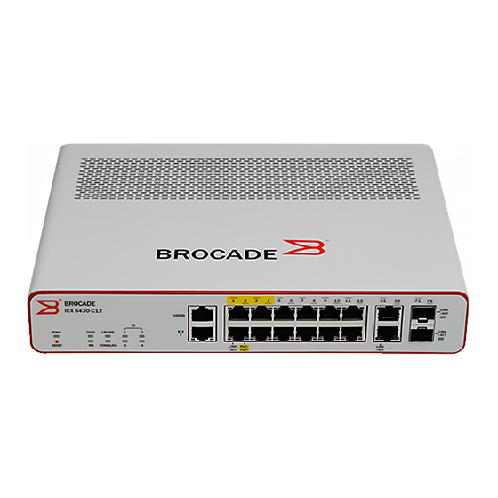
100/1GbE RJ45 ports C1 and C2, residing on slot 2 of the device, can be used as uplink ports or additional network connections. Additionally, an ICX 6430-C device contains two 100Mbps/1GbE small form factor pluggable (SFP) ports (ports F1 and F2). These ports reside on slot 3 of the switch and can be used as uplink ports. -
Page 15: System Status Leds
Port, system, and power status LEDs FIGURE 4 Port status LEDs an ICX 6430-C12 device Port status LEDs PoE/PoE+ LEDs Table 2 lists the port status LEDs on an ICX 6430-C device and their corresponding conditions and status. TABLE 2 Port status LEDs Condition Status... -
Page 16: Network Connection Status Leds
Port, system, and power status LEDs FIGURE 5 System status LEDs on an ICX 6430-C12 device System status LEDs Table 3 lists the system status LEDs on an ICX 6430-C device and their corresponding conditions and status. TABLE 3 System status LEDs Condition... - Page 17 Verify that the connection to the other network device has been properly made. • If the other actions do not resolve the problem, try using a different port or a different cable. Brocade ICX 6430-C Compact Switch Hardware Installation Guide 53-1002817-02...
- Page 18 • If the other actions do not resolve the problem, try using a different port or a different cable. If a problem persists after taking these actions, contact Brocade Technical Support. Brocade ICX 6430-C Compact Switch Hardware Installation Guide 53-1002817-02...
-
Page 19: Power Supplies
Power supplies Power supplies An ICX 6430-C device has one standard power supply receptacle on the rear panel of the device for the AC power cord (Figure FIGURE 6 ICX 6430-C AC power connection Kensington lock hole AC power supply socket Power supply usage The maximum power capacity of the ICX 6430-C12 device is 100W. - Page 20 Power supplies Brocade ICX 6430-C Compact Switch Hardware Installation Guide 53-1002817-02...
- Page 21 In this chapter • Items included with an ICX 6430-C device ......11 • Summary of installation tasks ........12 •...
-
Page 22: Summary Of Installation Tasks
Do not install the device in an environment where the operating ambient temperature might exceed 40 ο C (104 ο F). CAUTION Make sure the airflow around the front, sides, and back of the device is not restricted. Brocade ICX 6430-C Compact Switch Hardware Installation Guide 53-1002817-02... -
Page 23: Lifting Precautions
The mark is your assurance that the power cord can be used safely with the device. Brocade ICX 6430-C Compact Switch Hardware Installation Guide 53-1002817-02... -
Page 24: Preparing The Installation Site
Temperature: Because the temperature within a rack assembly may be higher than the ambient room temperature, check that the rack-environment temperature is within the specified operating temperature range. (Refer to “Operating environment” on page 38.) Brocade ICX 6430-C Compact Switch Hardware Installation Guide 53-1002817-02... -
Page 25: Installing The Device
Mount the devices you install in a rack or cabinet as low as possible. Place the heaviest device at the bottom and progressively place lighter devices above. Desktop installation Complete the following steps to install the ICX 6430-C device on a desktop or other flat surface. FIGURE 7 Attaching the adhesive feet... -
Page 26: Rack Mount Installation
1. Remove the rack mount kit from the shipping carton. The kit contains two L-shaped mounting brackets and six sink-head screws. 2. Using a Phillips screwdriver, attach the mounting brackets to the sides of the device using six sink-head screws, as illustrated in Figure 8. Brocade ICX 6430-C Compact Switch Hardware Installation Guide 53-1002817-02... - Page 27 Installing the device FIGURE 8 Attaching the mounting brackets for an ICX 6430-C device 3. Remove the two-post rack kit from the shipping carton. The kit contains four rack-mounting screws and four cage nuts. 4. Insert the cage nuts in the two-post rack where you want to mount the device. See Figure 5.
-
Page 28: Wall Mount Installation
To mount the device to a wall using the wall mount brackets, see “Wall mount installation using wall mount brackets”. NOTE When mounting the device on a wall, Brocade recommends that you mount the device with the port side down. Brocade ICX 6430-C Compact Switch Hardware Installation Guide 53-1002817-02... - Page 29 4. Use the #2 Phillips screwdriver to secure the two wall mount screws into the wall mount anchors. Leave a gap of 4.0 to 4.5 mm between the screw head and the wall. See Figure Brocade ICX 6430-C Compact Switch Hardware Installation Guide 53-1002817-02...
- Page 30 Installing the device FIGURE 10 Preparing to wall mount the device Drilled holes in wall Wall mount screws Wall mount anchors 4.0- 4.5 mm space between screw head and wall Brocade ICX 6430-C Compact Switch Hardware Installation Guide 53-1002817-02...
- Page 31 See Figure 11 Figure Brocade ICX 6430-C Compact Switch Hardware Installation Guide 53-1002817-02...
- Page 32 Installing the device FIGURE 11 Wall mounting the ICX 6430-C device - View of rear panel FIGURE 12 Wall mounting the ICX 6430-C device - View of the top panel Brocade ICX 6430-C Compact Switch Hardware Installation Guide 53-1002817-02...
- Page 33 When mounting the device on a wall, Brocade recommends that you mount the device with the port side down. To mount the ICX 6430-C device to a wall, use the rack-mount kit that can be ordered seperately from the device (Brocade Part Number: ICX6400-RMK). The rack-mount kit is not included with the device.
-
Page 34: Mounting The Device With A Magnet
8 cm clearance is recommended on each side. CAUTION Do not install the switch in a position where it can easily become unstable and fall, causing injury or damage to the switch. Brocade ICX 6430-C Compact Switch Hardware Installation Guide 53-1002817-02... - Page 35 Figure CAUTION The magnet sheet can only be placed against the bottom panel of the device. Do not attempt to attach the magnet sheet to any other panels on the device. Brocade ICX 6430-C Compact Switch Hardware Installation Guide 53-1002817-02...
- Page 36 Installing the device FIGURE 15 Attaching the logo side of the magnet sheet to the bottom panel of the ICX 6430-C device NOTE Do not install the rubber feet or remove the rubber feet if they are already installed. Brocade ICX 6430-C Compact Switch Hardware Installation Guide...
- Page 37 When mounting the device on a vertical metal surface, Brocade recommends that you mount the device with the port side down. Complete the following steps to securely mount an ICX 6430-C device on a metal surface or metal wall: 1. Ensure that the magnet sheet is attached to the bottom panel of the device. See “”...
- Page 38 CAUTION Do not mount the ICX 6430-C device directly underneath a desktop surface with the top panel facing downward. Only mount the ICX 6430-C device underneath a desktop by attaching it to the metal side surface of the desk, with the front panel and ports facing downward.
- Page 39 Ensure that adequate ventilation is provided for the system. A 7.62 cm (3-inch) clearance is recommended on each side. FIGURE 18 Mounting an ICX 6430-C device underneath a metal desktop using the magnet mount Magnet Metal desk Brocade ICX 6430-C Compact Switch Hardware Installation Guide...
-
Page 40: Powering On The System
Powering on the system FIGURE 19 The ICX 6430-C device securely mounted underneath a metal desk with the port side facing down Powering on the system After you complete the physical installation, you can power on the system. NOTE The socket should be installed near the equipment and should be easily accessible. -
Page 41: Ip Address Configuration
IP address that has a network mask with 24 significant (“mask”) bits. By default, the CLI displays network masks in classical IP address format (for example, 255.255.255.0). You can change the display to the prefix format. Brocade ICX 6430-C Compact Switch Hardware Installation Guide 53-1002817-02... - Page 42 IP address configuration Brocade ICX 6430-C Compact Switch Hardware Installation Guide 53-1002817-02...
-
Page 43: Managing An Icx 6430-C Device
TABLE 6 Temperature thresholds Model Warning level temperature threshold Critical (shutdown) temperature threshold °C) °C) ICX 6430-C12 Brocade recommends setting the 88°C warning level temperature no higher than 83°C. Brocade ICX 6430-C Compact Switch Hardware Installation Guide 53-1002817-02... -
Page 44: Displaying The Temperature
When the temperature crosses the critical (shutdown) threshold levels, the device will reset after 5 minutes. The following console and syslog message is displayed: !!! Temperature is over shutdown level, please shutdown your stack unit 1 to avoid hw damage!!! Brocade ICX 6430-C Compact Switch Hardware Installation Guide 53-1002817-02... - Page 45 Temperature settings NOTE Brocade recommends that you shut down your stack unit to avoid any hardware damage. Brocade ICX 6430-C Compact Switch Hardware Installation Guide 53-1002817-02...
- Page 46 Temperature settings Brocade ICX 6430-C Compact Switch Hardware Installation Guide 53-1002817-02...
-
Page 47: Chapter 5 Hardware Specifications
(AC) supply rating (watts) ICX 6430-C12 100 - 240 V 100 Watts TABLE 8 ICX 6430-C MAX Power with 100% Traffic Throughput and Maximum PoE Load AC Input Voltage Switch Only Switch Only Switch Switch & PoE Switch & PoE... -
Page 48: Physical Dimensions And Weight
For optimal performance, operate or store your device in compliance with the following environmental conditions. Operating environment Table 10 provides the operating and storage environment specifications for an ICX 6430-C device. Table 11 provides the humidity environment specifications for an ICX 6430-C device. Table 12 provides the storage altitude environment specifications for an ICX 6430-C device. -
Page 49: Cable Specifications
NOTE Brocade recommends that you use the power cord that is shipped with the device. For an ICX 6430-C device to operate at 100V, the power cord should be C13 type connector with 10A rating or better (NEMA-5-15 plug). For an ICX 6430-C device to operate at 240V, the power cord should be C13 type connector with 10A rating or better. - Page 50 Pinouts and signalling Brocade ICX 6430-C Compact Switch Hardware Installation Guide 53-1002817-02...
-
Page 51: Chapter 6 Troubleshooting
Verify that all system components have been properly installed. If one or more components appear to be malfunctioning (such as the power cord or network cabling), test them in an alternate environment where you are sure that all the other components are functioning properly. Brocade ICX 6430-C Compact Switch Hardware Installation Guide 53-1002817-02... - Page 52 Diagnosing switch indicators Brocade ICX 6430-C Compact Switch Hardware Installation Guide 53-1002817-02...
-
Page 53: Regulatory Statements
Machine noise information regulation - 3. GPSGV, the highest sound pressure level value is 70.0 dB(A) in accordance with EN ISO 7779. Maschinenlärminformations-Verordnung - 3. GPSGV, der höchste Schalldruckpegel beträgt 70.0 dB(A) gemäss EN ISO 7779. Brocade ICX 6430-C Compact Switch Hardware Installation Guide 53-1002817-02... -
Page 54: Japan (Vcci)
Class A device (Broadcasting Communication Device for Office Use): This device obtained EMC registration for office use (Class A), and may be used in places other than home. Sellers and/or users need to take note of this. Brocade ICX 6430-C Compact Switch Hardware Installation Guide 53-1002817-02... -
Page 55: China
English translation of above statement This is a Class A product. In a domestic environment this product may cause radio interference, in which case the user may be required to take adequate measures. Brocade ICX 6430-C Compact Switch Hardware Installation Guide 53-1002817-02... -
Page 56: Bsmi Statement (Taiwan)
Warning: This is a class A product. In a domestic environment this product may cause radio interference in which case the user may be required to take adequate measures. For the ICX 6400-EPS1500 device only: Brocade ICX 6430-C Compact Switch Hardware Installation Guide 53-1002817-02... -
Page 57: Regulatory Compliance
Immunity: • EN 61000-6-1, Electromagnetic Compatibility, Generic Standard • EN 55024, Information Technology equipment - Immunity Characteristics Safety: • BI-NAT CSA 60950-1-07/UL 60950-1 Second Edition • EN 60950-1:2006 • IEC 60950-1:2005 Brocade ICX 6430-C Compact Switch Hardware Installation Guide 53-1002817-02... - Page 58 Regulatory compliance Brocade ICX 6430-C Compact Switch Hardware Installation Guide 53-1002817-02...
-
Page 59: Cautions And Danger Notices
PRECAUCIÓN Use un circuito derivado separado para cada cordón de alimentación de CA, con lo que se proporcionará redundancia en caso de que uno de los circuitos falle. Brocade ICX 6430-C Compact Switch Hardware Installation Guide 53-1002817-02... - Page 60 Si usted borra accidentalmente la configuración en un sistema ya configurado, introduzca el comando write memory (escribir memoria) para guardar la configuración en ejecución en el archivo startup-config. Brocade ICX 6430-C Compact Switch Hardware Installation Guide 53-1002817-02...
- Page 61 Freiraum, auf beiden Seiten jeweils 8 cm Freiraum empfohlen. PRECAUCIÓN Asegúrese de proporcionar una ventilación adecuada al sistema. Se recomienda dejar 3 cm de espacio libre por encima del dispositivo y 8 cm a cada lado. Brocade ICX 6430-C Compact Switch Hardware Installation Guide 53-1002817-02...
-
Page 62: Danger Notices
Danger notices CAUTION Do not mount the ICX 6430-C device directly underneath a desktop surface with the top panel facing downward. Only mount the ICX 6430-C device underneath a desktop by attaching it to the metal side surface of the desk, with the front panel and ports facing downward. - Page 63 Monte los instrumentos que instale en un bastidor o armario lo más bajos posible. Ponga el instrumento más pesado en la parte inferior y los instrumentos progresivamente más livianos más arriba. Brocade ICX 6430-C Compact Switch Hardware Installation Guide 53-1002817-02...
- Page 64 Pour des raisons de sécurité, la dragonne ESD doit contenir une résistance de série 1 méga ohm. PELIGRO Por razones de seguridad, la correa de muñeca ESD deberá contener un resistor en serie de 1 mega ohmio. Brocade ICX 6430-C Compact Switch Hardware Installation Guide 53-1002817-02...
Need help?
Do you have a question about the ICX 6430-C and is the answer not in the manual?
Questions and answers