
Related Manuals for Brocade Communications Systems ICX 7250-24G


Summary of Contents for Brocade Communications Systems ICX 7250-24G
- Page 1 53-1003622-02 27 April 2015 Brocade ICX 7250 Switch Hardware Installation Guide Supporting FastIron Software Release 08.0.30...
- Page 2 United States government. The authors and Brocade Communications Systems, Inc. assume no liability or responsibility to any person or entity with respect to the accuracy of this document or any loss, cost, liability, or damages arising from the information contained herein or the computer programs that accompany it.
-
Page 3: Table Of Contents
Contents Preface............................. 7 Document conventions..................7 Text formatting conventions..............7 Command syntax conventions.............. 7 Notes, cautions, and warnings.............. 8 Brocade resources.................... 9 Contacting Brocade Technical Support.............9 Document feedback..................10 About This Document......................11 What's new in this document................11 Supported software..................11 Overview.......................... - Page 4 Items included with the EPS4000..............39 General requirements................... 39 Summary of installation tasks............... 39 Installation precautions................. 40 General precautions................40 Lifting precautions................40 Power precautions................41 Preparing the installation site................41 Rack-mount installation considerations..........41 Installing the device..................42 Desktop installation................42 Mounting an external power supply in a rack (2-post)...... 43 Installing an RPS17 Power Supply Unit (PSU)..........
- Page 5 Removing a copper or fiber-optic module........... 69 Installing a fiber-optic transceiver............70 Cabling a fiber-optic transceiver............71 Cleaning the fiber-optic connectors.............72 Brocade ICX 7250 Switch Technical Specifications..............73 Troubleshooting ........................85 Diagnosing switch indicators................85 Installation................... 85 Power and cooling problems...............85 In-band access..................86 Regulatory Statements......................87 CE Statement....................87 China ROHS....................
- Page 6 Brocade ICX 7250 Switch Hardware Installation Guide 53-1003622-02...
-
Page 7: Preface
Preface ● Document conventions......................7 ● Brocade resources......................9 ● Contacting Brocade Technical Support................9 ● Document feedback......................10 Document conventions The document conventions describe text formatting conventions, command syntax conventions, and important notice formats used in Brocade technical documentation. Text formatting conventions Text formatting conventions such as boldface, italic, or Courier font may be used in the flow of the text to highlight specific words or phrases. -
Page 8: Notes, Cautions, And Warnings
Notes, cautions, and warnings Convention Description Syntax components displayed within square brackets are optional. Default responses to system prompts are enclosed in square brackets. { x | y | z } A choice of required parameters is enclosed in curly brackets separated by vertical bars. -
Page 9: Brocade Resources
Brocade resources Brocade resources Visit the Brocade website to locate related documentation for your product and additional Brocade resources. You can download additional publications supporting your product at www.brocade.com. Select the Brocade Products tab to locate your product, then click the Brocade product name or image to open the individual product page. -
Page 10: Document Feedback
Document feedback • Brocade Supplemental Support augments your existing OEM support contract, providing direct access to Brocade expertise. For more information, contact Brocade or your OEM. • For questions regarding service levels and response times, contact your OEM/Solution Provider. Document feedback To send feedback and report errors in the documentation you can use the feedback form posted with the document or you can e-mail the documentation team. -
Page 11: About This Document
About This Document ● What's new in this document...................11 ● Supported software......................11 What's new in this document The following table lists the new information added to this guide for FastIron release 08.0.30. TABLE 1 Summary of enhancements in FastIron release 08.0.30 Feature Description Location... - Page 12 Supported software Brocade ICX 7250 Switch Hardware Installation Guide 53-1003622-02...
-
Page 13: Overview
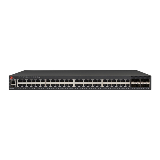
The ICX 7250 Ethernet switch device is available in the following models. TABLE 2 ICX 7250 Models Model Description ICX 7250-24G 24 fixed 10/100/1000Base-T, non-PoE ports, 4 SFP 1-GbE uplink ports, no stacking, no EPS4000 connection ICX 7250-24 24 fixed 10/100/1000Base-T, non-PoE ports, 8 SFP+ 1-GbE or 10-GbE uplink or... -
Page 14: Network And Management Interfaces
3. Slot 1 (10/100/1000 Mbps ports - RJ-45) 4. Slot 2 (SFP+ uplink or stacking ports) 5. Reset 6. USB port NOTE 24-port devices have similar front panels. For the ICX 7250-24G, the Slot 2 ports are SFP ports. Brocade ICX 7250 Switch Hardware Installation Guide 53-1003622-02... - Page 15 24-port models and the 48-port models. TABLE 3 Slot designations for ICX 7250 devices Device Slot 1 (10/100/1000 BASE-T ports) Slot 2 (SFP and SFP+ ports) ICX 7250-24G RJ-45 ports 1-24 SFP ports 1-4 ICX 7250-24 RJ-45 ports 1-24 SFP+ ports 1-8...
- Page 16 SFP or SFP+ fiber ports The ICX 7250-24G contains four small form factor pluggable (SFP) ports (ports 1 through 4). The top row consists of ports 1 and 3, and the bottom row consists of ports 2 and 4. These ports reside on slot 2 of the switch and can be used as uplink (data) ports.
- Page 17 Specifying a management port • stack_unit --Specifies the stack unit ID. For models that support stacking, the range is from 1 through the maximum number of devices (units) that can be supported in the stack. • slot --Specifies the slot number. Stacking ports are in slot 2. •...
- Page 18 The port is providing PoE or PoE+ power to a connected device. The port is not providing PoE or PoE + power. SFP (F1 - F4) for ICX 7250-24G On/Flashing Green The SFP port is operating at 1 devices Gbps. Flashing indicates the port is transmitting and receiving user packets at 1 Gbps.
- Page 19 Overview TABLE 4 Port status LEDs (Continued) Condition Status On/Flashing Yellow The SFP+ port is operating at 1 Gbps. Flashing indicates the port is transmitting and receiving user packets at 1 Gbps. A link is not established with a remote port. Out-of-band management port On/Flashing Green (RJ-45)
- Page 20 Overview 1. ICX 7250-24G LEDs 2. ICX 7250-24, ICX 7250-24P, ICX 7250-48 LEDs 3. ICX 7250-48P LEDs TABLE 5 System status LEDs Condition Status Green Power supply is operating normally. Yellow Power supply fault. Power supply off. EPS1 and EPS2 (for supported...
- Page 21 You should keep the connector covered when not in use. 1. Fan 2. External power supply (EPS4000) connector with cover on 3. AC power supply socket TABLE 6 EPS4000 connectors on the ICX 7250 models Model EPS4000 connectors ICX 7250-24G Brocade ICX 7250 Switch Hardware Installation Guide 53-1003622-02...
- Page 22 Number of PoE ports supported Number of PoE+ ports from AC line input (Watts) with internal power supply supported with internal power supply ICX 7250-24G 44.4 ICX 7250-24 57.6 ICX 7250-24P 454.0 23 PoE ports (class 3) ICX 7250-48 69.5 ICX 7250-48P 942.0...
-
Page 23: Installation
Installation ● Items included with the ICX 7250 device................ 23 ● Configuration requirements.....................24 ● Summary of installation tasks..................24 ● Installation precautions....................24 ● Preparing the installation site..................26 ● Installing the device......................26 ● Connecting devices in a traditional stack................ 31 ●... -
Page 24: Configuration Requirements
Configuration requirements Configuration requirements To manage the ICX 7250, you need a management station, such as a PC running a terminal emulation application, for serial connection to the device. Use the serial connection to perform basic configuration tasks, including assigning an IP address and network mask to the system. -
Page 25: Lifting Precautions
Lifting precautions CAUTION Make sure the airflow around the front, sides, and back of the device is not restricted. Lifting precautions DANGER Make sure the rack housing the device is adequately secured to prevent it from becoming unstable or falling over. DANGER Mount the devices you install in a rack as low as possible. -
Page 26: Preparing The Installation Site
Preparing the installation site Preparing the installation site Before installing the device, plan its location and orientation relative to other devices and equipment. Cabling infrastructure Ensure that the proper cabling is installed at the site. For information about supported SFP and SFP+ transceivers and cable lengths and types, refer to the Brocade optics family datasheet. -
Page 27: Desktop Installation
Desktop installation DANGER Mount the devices you install in a rack as low as possible. Place the heaviest device at the bottom and progressively place lighter devices above. Desktop installation Complete the following steps to install the ICX 7250 device on a desktop or other flat surface. NOTE The device shown in the diagram may be different from the one you have. - Page 28 Installation NOTE You need a #2 Phillips screwdriver for rack mount installation. Complete the following steps to mount devices in a rack. The example shows a front-mounting. 1. Remove the rack mounting kit from the shipping carton. The kit contains two L-shaped mounting brackets and two sets of eight sink-head screws.
-
Page 29: Wall Mount Installation
Wall mount installation FIGURE 13 Installing the device in a two-post rack 1. Rack-mounting screws 2. Cage nuts 6. If installing a single device only, proceed to Powering on the system on page 33. If installing multiple devices, mount them in the rack, one above the other. Wall mount installation NOTE You need a #2 Phillips screwdriver, a hammer, and a drill for wall mount installation. - Page 30 Installation FIGURE 14 Attaching the wall mount brackets 3. Drill two holes on the wall where you want to mount the device. 4. Hammer two wall mount anchors into the holes on the wall. 5. Use the two wall mount screws to fasten the device to the wall mount anchors. Brocade ICX 7250 Switch Hardware Installation Guide 53-1003622-02...
-
Page 31: Connecting Devices In A Traditional Stack
Connecting devices in a traditional stack FIGURE 15 Wall mounting the device 1. Drilled holes 2. Wall mount anchors 3. Wall mount screws Connecting devices in a traditional stack ICX 7250 devices can operate as standalone devices and also as members of traditional stacks. A stack is a group of devices—Brocade stackable units and their connected stacking links—that are connected so that the stack is managed as a single entity. -
Page 32: Stacking Configuration Requirements
Stacking configuration requirements FIGURE 16 Stacking ports 1. Slot 2 (SFP+ uplink or stacking ports) - StackID/Slot/Port Stacking configuration requirements Before configuring the traditional stack using the CLI, physically connect the devices using stacking cables. For information about configuring a stack, refer to the FastIron Ethernet Switch Stacking Configuration Guide. -
Page 33: Powering On The System
Powering on the system • For the first device in the stack, ports (1/2/1, 1/2/2) are being used as stacked ports. • For the second device in the stack, ports (2/2/1, 2/2/2 and 2/2/3, 2/2/4) are being used as stacked ports. - Page 34 Installation NOTE The socket should be installed near the equipment and should be easily accessible. 1. Remove the power cord from the shipping container. 2. Install the power cord clip. 3. Attach the AC power cord to the AC connector on the rear panel. 4.
-
Page 35: Installing The Eps4000
Installing the EPS4000 ● EPS4000 external power supply..................35 ● Items included with the EPS4000................... 39 ● General requirements..................... 39 ● Summary of installation tasks..................39 ● Installation precautions....................40 ● Preparing the installation site..................41 ● Installing the device......................42 ●... -
Page 36: Features And Benefits
• ICX 7250-48 • ICX 7250-48P NOTE The ICX 7250-24G is not supported by the EPS4000. Features and benefits • Hosts up to four hot-swappable RPS17 power supply units (PSUs). • Provides N:1 power redundancy at 12 V with each PSU. -
Page 37: Leds
LEDs supply. There is a RESET button next to the LEDs. There are port LEDs for each of the management ports. Both the serial port and the out-of-band Ethernet management ports use RJ-45 connectors. The slots for the RPS17 PSUs are covered with panels. These must be removed to install the PSU. FIGURE 19 EPS4000 front panel 1. - Page 38 Installing the EPS4000 FIGURE 21 EPS4000 LEDs 1. Ex.y: Power status indicator (54 V), where x = EPS4000 connector (1-8), y = Channel or port (1-2) 2. CONFIG: EPS configuration mode indicator 3. Rx.y: Power status indicator (12 V), where x = EPS4000 connector (1-8), y = Channel or port (1-2) The following table describes the functions of the EPS4000 LEDs.
-
Page 39: Items Included With The Eps4000
Items included with the EPS4000 TABLE 9 System Status LEDs on the EPS4000 (Continued) State Description Amber Manual configuration mode Management port LED Green Management port link up at 100BASE-T mode (Left down) Management port link up at 10BASE-T mode or link is down Management port LED Blinking green Indicates management port receive and transmit activity... -
Page 40: Installation Precautions
Installation precautions TABLE 10 Installation tasks (Continued) Task number Task Where to find more information Unpack the device and all included accessories. Items included with the EPS4000 page 39 section Install the device on a desktop, or in an equipment rack. Installing the device on page 42 section... -
Page 41: Power Precautions
Power precautions Power precautions CAUTION Use a separate branch circuit for each power cord, which provides redundancy in case one of the circuits fails. CAUTION Ensure that the device does not overload the power circuits, wiring, and over-current protection. To determine the possibility of overloading the supply circuits, add the ampere (amp) ratings of all devices installed on the same circuit as the device. -
Page 42: Installing The Device
Installing the device • Temperature: Because the temperature within a rack assembly may be higher than the ambient room temperature, check that the rack-environment temperature is within the specified operating temperature range. • Airflow: Be sure that the airflow direction for all equipment in a rack is the same or consistent. •... -
Page 43: Mounting An External Power Supply In A Rack (2-Post)
Mounting an external power supply in a rack (2-post) FIGURE 22 Attaching the adhesive feet to the device 2. Set the device on a flat surface near an AC power source, making sure there is the specified amount of space on all sides of the device for proper airflow. Mounting an external power supply in a rack (2-post) DANGER Make sure the rack housing the device is adequately secured to prevent it from becoming... - Page 44 Installing the EPS4000 FIGURE 23 Attaching the mounting brackets to the device 3. Mount the external power supply in a rack using four rack-mounting screws. 4. Use the four cage nuts to screw the device to the rack mount holes. FIGURE 24 Installing the external power supply in a rack Brocade ICX 7250 Switch Hardware Installation Guide 53-1003622-02...
-
Page 45: Installing An Rps17 Power Supply Unit (Psu)
Installing an RPS17 Power Supply Unit (PSU) 1. Rack-mounting screws 2. Cage nuts 5. If installing multiple external power supplies, mount them in the rack one above the other. Installing an RPS17 Power Supply Unit (PSU) You can install a new RPS17 PSU into EPS4000 while the device is powered on and running. NOTE While installing a PSU, wear an ESD wrist strap. -
Page 46: Uninstalling An Rps17 Power Supply Unit (Psu)
Uninstalling an RPS17 Power Supply Unit (PSU) Uninstalling an RPS17 Power Supply Unit (PSU) You can uninstall an RPS17 PSU from EPS4000 while the device is powered on and running. NOTE While uninstalling a PSU, wear an ESD wrist strap. DANGER For safety reasons, the ESD wrist strap should contain a series 1 megaohm resistor. - Page 47 Installing the EPS4000 NOTE The headers on the cords are color coded to help you connect them correctly to the switch and the EPS4000. You must connect the cables tightly using a flat-blade screwdriver for the latching screws. You could see intermittent power supply failures otherwise. The following figure shows EPS4000 DC power cords FIGURE 27 DC power cords for the EPS4000 1.
- Page 48 Installing the EPS4000 NOTE You can connect either end of the cable first. Hot insertion is supported for cable installation. NOTE The device shown in the diagram may be different from the one you are using. The process to remove the EPS4000 faceplate is the same.
-
Page 49: Powering On The System
Powering on the system Powering on the system After you complete the physical installation, you can power on the system. NOTE The socket should be installed near the equipment and should be easily accessible. 1. Remove the power cord from the shipping container. 2. -
Page 50: Eps4000 External Power Supply Technical Specifications
1U; 19-inch rack-mountable or desktop Power inlet C14 for AC power Power outlet Custom connector for DC power to all ICX 7250 devices except ICX 7250-24G. Power supply units (PSU) Up to four RPS17, field-replaceable units (FRU) Fans One fan per installed RPS17... - Page 51 Installing the EPS4000 Other System component Description RESET Reset button for hardware reset without power cycling. There is a hole in the front panel to allow access. Sets EPS4000 to factory default settings. RJ-45 console port Console port for serial access to the device for management Serial cable RJ-45 console cable DB9 adaptor...
- Page 52 Installing the EPS4000 Regulatory compliance (EMC) • FCC Part 15, Subpart B (Class A) • EN 55022 (CE mark) (Class A) • EN 55024 (CE mark) (Immunity) for Information Technology Equipment • ICES-003 (Canada) (Class A) • AS/NZ 55022 (Australia) (Class A) •...
-
Page 53: Configuring The Device
Configuring the Device ● Configuration tasks......................53 ● PC or terminal attachment....................54 ● Password assignment..................... 54 ● IP address configuration....................56 ● Connecting network devices................... 60 ● Troubleshooting network connections................62 ● Testing connectivity......................63 DANGER The procedures in this manual are for qualified service personnel. Configuration tasks Follow the steps listed in the following table to configure the device. -
Page 54: Pc Or Terminal Attachment
PC or terminal attachment PC or terminal attachment You can access the CLI by attaching a serial cable to the console port. After you assign an IP address, you can access the system through Telnet or Brocade Network Advisor. Complete the following steps to attach a management station to the console port. 1. -
Page 55: Assigning Passwords
Assigning passwords The CLI contains the following access levels: • User EXEC - The level you enter when you first start a CLI session. At this level, you can view some system information but you cannot configure system or port parameters. •... -
Page 56: Recovering From A Lost Password
Recovering from a lost password Syntax: enable { super-user-password | read-only-password | port-config-password} text Passwords can be up to 32 characters long. Recovering from a lost password By default, the CLI does not require passwords. However, if a password has been configured for the device but the password has been lost, you can regain Super User access to the device using the following procedure. -
Page 57: Devices Running Layer 3 Software
Devices running Layer 3 software 1. At the opening CLI prompt, enter enable. device> enable 2. Enter the following command at the Privileged EXEC level prompt, and then press Enter . This command erases the factory test configuration if still present. device# erase startup-config CAUTION Use the erase startup-config command only for new systems. - Page 58 Configuring IP parameters for devices running Layer 3 software 3. Access the global configuration level of the CLI by entering the following command. device# configure terminal Brocade(config)# 4. Configure the IP addresses and mask addresses for the interfaces on the router. device(config)# interface ethernet 2 device(config)# ip address 10.22.3.44 255.255.255.0 NOTE...
- Page 59 Deleting an IP address unstable links between a Layer 3 device and other devices. You can configure up to four loopback interfaces on a Layer 3 device. You can add up to 24 IP addresses to each loopback interface. NOTE If you configure the device to use a loopback interface to communicate with a BGP4 neighbor, you must also configure a loopback interface on the neighbor and configure the neighbor to use that loopback interface to communicate with the Brocade device.
-
Page 60: Connecting Network Devices
Connecting network devices To delete all IP addresses from an interface, enter the following command. Brocade(config-if-1/1/1)# no ip address * Syntax: [no] ip address { ip-addr | * } Connecting network devices Brocade devices support connections to other vendors’ routers, switches, and hubs, as well other Brocade devices. -
Page 61: Connecting To Workstations, Servers, Or Routers
Connecting to workstations, servers, or routers FIGURE 29 UTP crossover cable FIGURE 30 Straight-through cable Connecting to workstations, servers, or routers Straight-through UTP cabling is required for direct UTP attachment to workstations, servers, or routers using network interface cards (NICs). Fiber cabling is required for direct attachment to Gigabit NICs or switches and routers through fiber ports. -
Page 62: Connecting A Network Device To A Fiber Port
Digital optical monitoring NOTE 10 Gbps optical transceivers are not supported on ICX 7250-24G devices. You can configure your device to monitor optical transceivers in the system, either globally or by specified port. When this feature is enabled, the system monitors the temperature and signal power levels for the optical transceivers in the specified ports. -
Page 63: Testing Connectivity
Testing connectivity Testing connectivity Test for connectivity by observing the LEDs related to network connection. Pinging an IP address To verify that a device can reach another device through the network, enter a command similar to the following at any level of the CLI. device>... -
Page 64: Tracing A Route
Tracing a route TABLE 12 Network connection-related LED states (Continued) Desired Meaning Abnormal Meaning or action state state The port is A link is not established with the PoE (Green) providing PoE device. You can do the following: (1-24/48) power to a •... -
Page 65: Managing An Icx 7250 Device
Managing an ICX 7250 Device ● Managing temperature settings..................65 ● Displaying CPU usage....................68 ● Removing MAC address entries..................68 DANGER The procedures in this manual are for qualified service personnel. Managing temperature settings The device contains temperature sensors that the software reads based on a configurable device poll time. -
Page 66: Displaying Syslog Messages For Temperature
TABLE 14 Temperature thresholds Model Low limit temperature High limit temperature Critical (shutdown) temperature TA (°C) TB (°C) TC (°C) ICX 7250-24G Brocade ICX 7250 Switch Hardware Installation Guide 53-1003622-02... -
Page 67: Changing The Temperature Warning Level
Changing the temperature warning level TABLE 14 Temperature thresholds (Continued) Model Low limit temperature High limit temperature Critical (shutdown) temperature TA (°C) TB (°C) TC (°C) ICX 7250-24 ICX 7250-24P 49 @ PSU 58 @ PSU ICX 7250-48P ICX 7250-48 34 @ PSU 41 @ PSU Changing the temperature warning level... -
Page 68: Displaying Cpu Usage
Displaying CPU usage To change the poll time, enter a command similar to the following at the global CONFIG level. Brocade(config)# chassis poll-time 200 Syntax: chassis poll-time value The value variable can be from 0 through 65535 seconds. Displaying CPU usage You can display the amount of the CPU in use. -
Page 69: Hardware Maintenance Schedule
Hardware maintenance schedule ● Copper or fiber-optic module replacement..............69 DANGER The procedures in this manual are for qualified service personnel. The ICX 7250 devices require minimal maintenance for their hardware components. However, Brocade recommends cleaning the fiber-optic connectors on a fiber-optic port and the connected fiber cable each time you disconnect the cable. -
Page 70: Installing A Fiber-Optic Transceiver
Installing a fiber-optic transceiver FIGURE 31 Unlocking the bail latch 1. Bail latch NOTE The bail latch may be attached to either the top or the bottom of the SFP transceiver. 4. Grasp the bail latch and pull the copper or fiber-optic module out of the port. FIGURE 32 Removing the fiber-optic module 5. -
Page 71: Cabling A Fiber-Optic Transceiver
Cabling a fiber-optic transceiver 1. Put on the ESD wrist strap and ground yourself by attaching the clip end to a metal surface (such as an equipment rack) to act as ground. 2. Remove the new transceiver from the protective packaging. 3. -
Page 72: Cleaning The Fiber-Optic Connectors
Cleaning the fiber-optic connectors Cleaning the fiber-optic connectors To avoid problems with the connection between the fiber-optic transceiver (SFP or SFP+) and the fiber cable connectors, Brocade strongly recommends cleaning both connectors each time you disconnect and reconnect them. Dust can accumulate in the connectors and cause problems, such as reducing the optic launch power. -
Page 73: Brocade Icx 7250 Switch Technical Specifications
1U; 19-inch rack-mountable; desktop- or wall-mountable Power inlet C14 for AC power Custom connector for DC power from EPS4000 (not available on the ICX 7250-24G) Power supplies Integrated AC power supply for system and PoE power External AC power supply (EPS4000) for redundant system power and extended PoE/PoE+ power (not applicable to the ICX 7250-24G). - Page 74 DIAG: Bicolor LED (green/amber) controlled by software to indicate the system is in diagnostic mode NOTE The following LEDs are not available on the ICX 7250-24G. EPS1: Bicolor LED (green/amber) indicates if the external power supply (EPS1) is operating normally...
- Page 75 Mini-USB to RJ-45 console cable: BPN 50-1000122-01 RJ-45 connector 2x6 stacked RJ-45 connectors for GbE data ports Weight and physical dimensions Model Height Width Depth Weight ICX 7250-24G 4.37 cm 44.0 cm 28 cm 3.6 kg 1.72 in 17.32 in 11 in 7.9 lb ICX 7250-24 4.37 cm...
- Page 76 Vibration 1 G sine, 0.4 gms random, 5-500 Hz 2.4 G sine, 1.1 gms random, 5-500 Hz Airflow ICX 7250-24G: 14.3 CFM (Maximum), 5.7 CFM (Typical) ICX 7250-24 : 14.0 CFM (Maximum), 5.7 CFM (Typical) ICX 7250-24P: 34.4 CFM (Maximum), 13.7 CFM (Typical) ICX 7250-48: 34.8 CFM (Maximum), 13.8...
- Page 77 Maximum Input line Maximum output power frequency input current protection inrush rating (DC) current ICX 7250-24G 65 W 100 - 240 VAC 50/60 Hz 1.5 A (rms) Line fused 40 A at 115 ICX 7250-24 (nominal) (nominal) 80 A at 230...
- Page 78 Brocade ICX 7250 Switch Technical Specifications Model name @100 VAC input @200 VAC input @-48 VDC input Minimum Notes number of power supplies ICX 7250-24G 0.56 A 0.35 A All ports down, no optics or 33.6 W 33.3 W cables connected.
- Page 79 Brocade ICX 7250 Switch Technical Specifications Model name @100 VAC input @200 VAC input @-48 VDC input Minimum Notes number of power supplies ICX 7250-24G 0.71 A 0.42 A 24 1-GbE and 4 10-GbE ports are 42.6 W 39.9 W linked UP ONLY.
- Page 80 @ Class 3 (15.4 W/port) Data port specifications (Ethernet) Model Port type Number of Description ports ICX 7250-24G GbE (copper) RJ-45 10/100/1000 ports GbE (optical) SFP uplink ports ICX 7250-24 GbE (copper) RJ-45 10/100/1000 ports 10 GbE Uplink or stacking SFP+ ports...
- Page 81 Brocade ICX 7250 Switch Technical Specifications Model Port type Number of Description ports ICX 7250-24P GbE (copper) RJ-45 10/100/1000 ports 10 GbE Uplink or stacking SFP+ ports (optical) ICX 7250-48 GbE (copper) RJ-45 10/100/1000 ports 10 GbE Uplink or stacking SFP+ ports (optical) ICX 7250-48P GbE (copper) RJ-45 10/100/1000 ports...
- Page 82 2 x 8 MB Compact Flash NAND 2 GB Main DDR3 (onboard IC) ICX 7250-24G: 1 GB ICX 7250-24: 2 GB ICX 7250-24P: 2 GB ICX 7250-48: 2 GB ICX 7250-48P: 2 GB Regulatory compliance (EMC) • FCC Part 15, Subpart B (Class A) •...
- Page 83 Brocade ICX 7250 Switch Technical Specifications • Section 1502 of the Dodd-Frank Wall Street Reform and Consumer Protection Act of 2010 - U.S. Conflict Minerals • 30/2011/TT-BCT - Vietnam circular • SJ/T 11363-2006 Requirements for Concentration Limits for Certain Hazardous Substances in EIPs (China) •...
- Page 84 Brocade ICX 7250 Switch Technical Specifications Brocade ICX 7250 Switch Hardware Installation Guide 53-1003622-02...
-
Page 85: Troubleshooting
Troubleshooting ● Diagnosing switch indicators...................85 Diagnosing switch indicators TABLE 15 Troubleshooting chart Symptom Action Power LED is Off • Check if internal power supply is disconnected. • Check connections between the device, the power cord, and the wall outlet. • Contact Technical Support. Power LED is Amber Internal power supply has failed. -
Page 86: In-Band Access
In-band access In-band access You can access the management agent in the device from anywhere within the attached network using Telnet, or other network management software. However, you must first configure the device with a valid IP address, subnet mask, and default gateway. If you have trouble establishing a link to the management agent, check to see if you have a valid network connection. -
Page 87: Regulatory Statements
Regulatory Statements ● CE Statement........................87 ● China ROHS........................87 ● BSMI statement (Taiwan)....................87 ● Canadian requirements....................88 ● China CC statement......................89 ● Europe and Australia (CISPR 22 Class A Warning)............89 ● FCC warning (US only)....................90 ● Germany......................... 90 ● KCC statement (Republic of Korea)................90 ●... -
Page 88: Canadian Requirements
Canadian requirements Warning: This is Class A product. In a domestic environment this product may cause radio interference in which case the user may be required to take adequate measures. Canadian requirements This Class A digital apparatus meets all requirements of the Canadian Interference-Causing Equipment Regulations, ICES-003 Class A. -
Page 89: China Cc Statement
China CC statement China CC statement Europe and Australia (CISPR 22 Class A Warning) This is a Class A product. In a domestic environment this product may cause radio interference in which case the user may be required to take adequate measures. Brocade ICX 7250 Switch Hardware Installation Guide 53-1003622-02... -
Page 90: Fcc Warning (Us Only)
FCC warning (US only) FCC warning (US only) This equipment has been tested and complies with the limits for a Class A computing device pursuant to Part 15 of the FCC Rules. These limits are designed to provide reasonable protection against harmful interference when the equipment is operated in a commercial environment. -
Page 91: Cautions And Danger Notices
Cautions and Danger Notices ● Cautions.......................... 91 ● Danger Notices....................... 94 Cautions A Caution statement alerts you to situations that can be potentially hazardous to you or cause damage to hardware, firmware, software, or data. Ein Vorsichthinweis warnt Sie vor potenziellen Personengefahren oder Beschädigung der Hardware, Firmware, Software oder auch vor einem möglichen Datenverlust Un message de mise en garde vous alerte sur des situations pouvant présenter un risque potentiel de dommages corporels ou de dommages matériels, logiciels ou de perte de données. - Page 92 Cautions and Danger Notices PRECAUCIÓN Asegúrese de que el flujo de aire en las inmediaciones de las partes anterior, laterales y posterior del instrumento no esté restringido. CAUTION Ensure that adequate ventilation is provided for the system. A 3 cm clearance is recommended above the device and 8 cm clearance is recommended on each side.
- Page 93 Cautions and Danger Notices MISE EN N'utilisez la commande erase startup-config que pour les nouveaux systèmes. Si vous GARDE entrez cette commande sur un système que vous avez déjà configuré, elle efface la configuration. Si vous effacez la configuration par accident sur un système configuré, entrez la commande write memory pour enregistrer la configuration actuelle dans le fichier startup- config.
-
Page 94: Danger Notices
Danger Notices PRECAUCIÓN Verifique que el instrumento no sobrecargue los circuitos de corriente, el cableado y la protección para sobrecargas. Para determinar la posibilidad de sobrecarga en los circuitos de suministros, añada las capacidades nominales de corriente (amp) de todos los instrumentos instalados en el mismo circuito que el instrumento. - Page 95 Cautions and Danger Notices GEFAHR Die Finger dürfen nicht versehentlich in das Ventilatorblech gesteckt werden, wenn dieses vom Gehäuse abgenommen wird. Der Ventilator kann sich unter Umständen noch mit hoher Geschwindigkeit drehen. DANGER Faites attention de ne pas accidentellement insérer vos doigts dans le boîtier du ventilateur lorsque vous l'enlevez du châssis.
- Page 96 Cautions and Danger Notices GEFAHR Ziehen Sie das Stromkabel aus allen Stromquellen, um sicherzustellen, dass dem Gerät kein Strom zugeführt wird. DANGER Débranchez le cordon d'alimentation de toutes les sources d'alimentation pour couper complètement l'alimentation du dispositif. PELIGRO Para desconectar completamente la corriente del instrumento, desconecte el cordón de corriente de todas las fuentes de corriente.
- Page 97 Cautions and Danger Notices Dangers related to equipment weight DANGER Make sure the rack housing the device is adequately secured to prevent it from becoming unstable or falling over. GEFAHR Stellen Sie sicher, dass das Gestell für die Unterbringung des Geräts auf angemessene Weise gesichert ist, so dass das Gestell oder der Schrank nicht wackeln oder umfallen kann.
- Page 98 Danger Notices Brocade ICX 7250 Switch Hardware Installation Guide 53-1003622-02...
Need help?
Do you have a question about the ICX 7250-24G and is the answer not in the manual?
Questions and answers