Brocade Communications Systems ICX 6650 Installation Manual
Hide thumbs
Also See for ICX 6650:
- Configuration manual (494 pages) ,
- Security configuration manual (332 pages) ,
- Hardware installation manual (83 pages)
Table of Contents
Advertisement
Quick Links
Advertisement
Table of Contents

Related Manuals for Brocade Communications Systems ICX 6650


Summary of Contents for Brocade Communications Systems ICX 6650
-
Page 1: Hardware Installation Guide
53-1002599-02 ® 20 September 2013 Brocade ICX 6650 Hardware Installation Guide... - Page 2 Export of technical data contained in this document may require an export license from the United States government. The authors and Brocade Communications Systems, Inc. shall have no liability or responsibility to any person or entity with respect to any loss, cost, liability, or damages arising from the information contained in this book or the computer programs that accompany it.
-
Page 3: Table Of Contents
Brocade ICX 6650 Overview Brocade ICX 6650 overview ....... . 17 Brocade ICX 6650 orderable models . - Page 4 Brocade ICX 6650 front panel LEDs ......51 Brocade ICX 6650 rear panel LEDs ......53 LED patterns .
- Page 5 Brocade ICX 6650 maintenance ......55 Diagnostic tests and monitoring ......55...
- Page 6 Appendix C Brocade ICX 6650 Cautions and Danger Notices Cautions..........81 Danger notices .
-
Page 7: About This Document
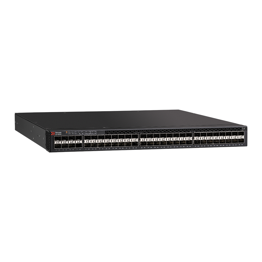
The ICX 6650 contains the following slots and Ethernet ports: • Slot 1 is located on the front of the ICX 6650 device and contains ports 1 through 56. Ports 1 through 56 are 1/10 GbE SFP+ ports. Refer to the following figure. -
Page 8: How This Document Is Organized
• Slot 2 is located on the back of the ICX 6650 device and contains ports 1 through 3 on the top row and port 4 on the bottom row. These ports are 2x40 GbE QSFP+. Refer to the following figure. -
Page 9: Document Conventions
Brocade ICX 6650 slot and Ethernet port numbering Document conventions This section describes text formatting conventions and important notice formats used in this document. Text formatting The narrative-text formatting conventions that are used are as follows: bold text Identifies command names... -
Page 10: Notice To The Reader
• Brocade ICX 6650 Hardware Installation Guide New • Brocade ICX 6650 Administration Guide • Brocade ICX 6650 Platform and Layer 2 Configuration Guide • Brocade ICX 6650 Layer 3 Routing Configuration Guide • Brocade ICX 6650 Security Configuration Guide •... -
Page 11: Additional Information
Brocade ICX 6650 slot and Ethernet port numbering • Brocade ICX 6650 Diagnostic Reference • Unified IP MIB Reference • Ports-on-Demand Licensing for the Brocade ICX 6650 The latest versions of these guides are posted at http://www.myBrocade.com/ethernetproducts. Additional information This section lists additional Brocade and industry-specific documentation that you might find helpful. - Page 12 Brocade ICX 6650 slot and Ethernet port numbering Brocade ICX 6650 Hardware Installation Guide 53-1002599-02...
-
Page 13: Brocade Icx 6650 Overview
Brocade ICX 6650 overview ........ -
Page 14: Brocade Icx 6650 Orderable Models
Description ICX6650-32-ADV Brocade ICX 6650 with 32 10 GbE SFP+ ports enabled. No power supplies or fan units (need to be ordered separately). Advanced software. Optional Ports on Demand (PoD) licenses to enable up to 56 10 GbE SFP+ ports and 6 QSFP+ ports can be ordered separately. -
Page 15: Views Of The Brocade Icx 6650 Switch
SKUs for creating custom ICX 6650 switch models Description ICX6650-8P10G-LIC-POD Ports on Demand license for Brocade ICX 6650, for 8×10 GbE SFP+ ports. ICX6650-2P40G-LIC-POD Ports on Demand license for Brocade ICX 6650, for two QSFP+ (40 GbE or 4×10 GbE) ports. RPS15-E 250 W AC power supply;... - Page 16 Ports 1/41 through 1/48 4x10 GbE QSFP-to-SFP breakout port 10 Ports 1/49 through 1/56 status/activity LED Figure 2 shows the back view of the Brocade ICX 6650 switch. FIGURE 2 Back view of the Brocade ICX 6650 Fan unit Ports 2/1 through 2/2...
-
Page 17: Ports-On-Demand Licensing
Ports-on-Demand licensing Ports-on-Demand licensing The Brocade ICX 6650 device features Ports-on-Demand licensing. With Ports-on-Demand licensing, software features do not require licenses and you can add port licenses as needed. A fully populated device supports 56 front-panel, dual-speed 1/10 GbE SFP+ ports, 4 rear panel 40 GbE QSFP+ ports, and 2 rear panel 4x10 GbE QSFP+ breakout ports. -
Page 18: Brocade Icx 6650 Slot And Ethernet Port Numbering
• Slot 2 is located on the back of the ICX 6650 device and contains ports 1 through 3 on the top row and port 4 on the bottom row. These ports are 2x40 GbE QSFP+. Refer to the following figure. -
Page 19: Supported Transceivers And Cables
Brocade Optics Family Data Sheet. Breakout cables The rear panel of the Brocade ICX 6650 device contains two 4x10 GbE ports which support the following: • QSFP+ to 4 SFP+ (4 x 10 GbE) direct attach copper breakout cables (see Figure •... - Page 20 Breakout cables Brocade ICX 6650 Hardware Installation Guide 53-1002599-02...
-
Page 21: Chapter 2 Installing The Brocade Icx
28. Unpacking the device The Brocade ICX 6650 device ships with all of the items listed below. Verify the contents of your shipping container. If any items are missing, please contact the place of purchase. Package contents (ICX6650-32-E-ADV, ICX6650-48-E-ADV, and... -
Page 22: Package Contents (Icx6650-32-Adv)
The filler panels must be in place if operating the switch with only one power supply and fan. Installation and safety considerations You can install the Brocade ICX 6650 in the following ways: • As a standalone unit on a flat surface. -
Page 23: Environmental Considerations
• Because the Brocade ICX 6650 can be ordered with fans that move air either front to back or back to front, be sure to orient your switch with the airflow pattern of any other devices in the rack. -
Page 24: Recommendations For Cable Management
Command Line Interface (CLI). Plug the device into a nearby power source that adheres to “Powering on the system” on page 34 the regulatory requirements outlined in this manual. Brocade ICX 6650 Hardware Installation Guide 53-1002599-02... -
Page 25: Installation Precautions
Do not install the device in an environment where the operating ambient temperature might exceed 40 ο C (104 ο F). CAUTION Make sure the air flow around the front and sides of the device is not restricted. CAUTION Never leave tools inside the device. Brocade ICX 6650 Hardware Installation Guide 53-1002599-02... -
Page 26: Lifting Precautions
The mark is your assurance that the power cord can be used safely with the device. Brocade ICX 6650 Hardware Installation Guide 53-1002599-02... -
Page 27: Installing The Device In A Rack Or Cabinet
2-Post rack mount installation NOTE Use the following procedure when installing the Brocade ICX 6650 device in a 2-post rack. For 4-post racks, follow the procedures in the section “4-Post rack mount installation”... - Page 28 8-32 x 5/16 in. screws. FIGURE 8 Attaching the brackets for Brocade ICX 6650 devices 2. Position the switch in the cabinet, providing temporary support under the switch until the rail kit is secured to the cabinet. 3. Attach the front right bracket to the rail rack using two 10-32 x 5/8 in. screws and the appropriate round or square retainer nuts.
-
Page 29: 4-Post Rack Mount Installation
Kits for 4-post rack mounting are not included in the shipping carton and must be ordered separately. NOTE Use the following procedure when installing the Brocade ICX 6650 device in a 4-post rack cabinet. For 2-post cabinets, follow the procedures in the section “2-Post rack mount installation”... - Page 30 Use the following steps to mount devices in a 4-post rack. CAUTION Do not use the hardware supplied in a 2-post rack mounting kit to mount a Brocade ICX 6650 device in a 4-post rack. Mounting the device in a 4-post rack requires additional hardware to prevent drooping from possible flexing and distortion of the 4-post rack when a device is not properly installed.
-
Page 31: Attaching A Pc Or Terminal
Use the following steps to attach a management station to the console port: 1. Connect a PC or terminal to the console management port on the back of the ICX 6650 device using the mini-USB serial console port cable (Part number 50-1000059-01. -
Page 32: Powering On The System
Except for the configurable models, each Brocade FastIron ICX 6650 Switch comes with two alternating-current (AC) power supplies. The Brocade FastIron ICX 6650 Switch also supports direct-current (DC) power supplies. The Brocade FastIron ICX 6650 Switch is capable of running on one power supply and one fan. The second set provide redundancy. -
Page 33: Installing And Replacing A Power Supply Unit
CAUTION For Brocade Brocade ICX 6650 devices, be sure that the airflow direction of the power supply unit matches that of the installed fan tray. The power supplies and fan trays are clearly labeled with either a green arrow with an “E”, or an orange arrow with an “I.”... - Page 34 B Temperature Readings: Current temperature : 31.0 deg-C sensor C Temperature Readings: Current temperature : 34.5 deg-C sensor D Temperature Readings: Current temperature : 30.5 deg-C Warning level..: 45.0 deg-C Shutdown level..: 85.0 deg-C Brocade ICX 6650 Hardware Installation Guide 53-1002599-02...
-
Page 35: Installing A Dc Power Supply
Use the following steps to install a DC power supply in the switch. CAUTION For Brocade ICX 6650 devices, be sure that the power type of the power supplies match. Both power supplies must be either AC or DC. AC and DC units cannot be mixed in a device. - Page 36 2. Before opening the package that contains the DC power supply, touch the bag of the switch casing to discharge any potential static electricity. Brocade recommends using an ESD wrist strap during installation. 3. Remove the DC power supply from the anti-static shielded bag. Brocade ICX 6650 Hardware Installation Guide 53-1002599-02...
- Page 37 When the device is powered on, the power LED on the front of the ICX 6650 device should turn green to confirm that the power supply is correctly installed and supplying power. Refer to the section “Brocade ICX 6650 front panel LEDs”...
-
Page 38: Dc-Dc Power Source Cautions
1. Remove any protector plugs from the transceivers and the ports. 2. Making sure that the bail (wire handle) is in the unlocked position, place the SFP+ transceiver in the correctly oriented position on the port, as shown in Figure Brocade ICX 6650 Hardware Installation Guide 53-1002599-02... - Page 39 SFP+ transceiver in the upper row of ports is with the gold-plated edge down. The correct position to insert an SFP+ transceiver in the lower row of ports is with the gold-plated edge up. FIGURE 17 Installing an SFP+ transceiver in a port slot Brocade ICX 6650 Hardware Installation Guide 53-1002599-02...
- Page 40 Installing an SFP+ transceiver Brocade ICX 6650 Hardware Installation Guide 53-1002599-02...
-
Page 41: Configuring The Brocade Icx 6650
In this chapter • Brocade ICX 6650 slot and Ethernet port numbering ....41 • Assigning permanent passwords ........42 •... -
Page 42: Assigning Permanent Passwords
• Slot 2 is located on the back of the ICX 6650 device and contains ports 1 through 3 on the top row and port 4 on the bottom row. These ports are 2x40 GbE QSFP+. Refer to the following figure. -
Page 43: Setting Passwords
3. While the system is booting, before the initial system prompt appears, enter b to enter the boot monitor mode. 4. Enter no password at the prompt. (You cannot abbreviate this command.) After the console prompt reappears, assign a new password. Brocade ICX 6650 Hardware Installation Guide 53-1002599-02... -
Page 44: Configuring Ip Addresses
IP address that has a network mask with 24 significant (“mask”) bits. By default, the CLI displays network masks in classical IP address format (example: 255.255.255.0). You can change the display to the prefix format. See the Brocade ICX 6650 Administration Guide. -
Page 45: Devices Running Layer 3 Software
Devices running Layer 3 software Before attaching equipment to a Brocade ICX 6650 switch, you must assign an interface IP address to the subnet on which the router will be located. You must use the serial connection to assign the first IP address. - Page 46 Brocade(config-if-1/1/1)# ip address 192.168.0.0 255.255.255.0 NOTE You also can enter the IP address and mask in CIDR format, as follows: Brocade(config-if-1/1/1)# ip address 192.168.0.0/24 Syntax: [no] ip address ip-addr ip-mask Syntax: [no] ip address ip-addr/mask-bits Brocade ICX 6650 Hardware Installation Guide 53-1002599-02...
- Page 47 1 as the routing interface for the VLAN. The last two commands change to the interface configuration level for the virtual interface and assign an IP address to the interface. Syntax: router-interface ve num Syntax: interface ve num Brocade ICX 6650 Hardware Installation Guide 53-1002599-02...
-
Page 48: Connecting Network Devices
For direct attachment from the device to a Gbps NIC, switch, or router, using a fiber optic transceiver, you will need fiber cabling with an LC connector. For information about transceivers supported on ICX 6650 devices, refer to the following Brocade website: http://www.myBrocade.com/downloads/documents/data_sheets/product_data_sheets/Optics_... - Page 49 To clean the fiber cable connectors, Brocade recommends using a fiber optic reel-type cleaner. When not using an SFP connector, make sure to keep the protective covering in place. Brocade ICX 6650 Hardware Installation Guide 53-1002599-02...
-
Page 50: Testing Connectivity
Test for connectivity by observing the LEDs related to network connection. Pinging an IP address To verify that a Brocade ICX 6650 device can reach another device through the network, enter a command similar to the following at any level of the CLI. -
Page 51: Brocade Icx 6650 Operation
• Brocade ICX 6650 rear panel LEDs ....... . 53 •... - Page 52 Brocade ICX 6650 front panel LEDs Figure 18 shows the LEDs on the Brocade ICX 6650 front panel. The up-arrow port status LEDs for the 10/1 GbE ports correspond to the upper, odd numbered ports; the down-arrow port status LEDs correspond to the lower, even numbered ports...
-
Page 53: Brocade Icx 6650 Rear Panel Leds
Brocade ICX 6650 rear panel LEDs Brocade ICX 6650 rear panel LEDs The Brocade ICX 6650 has the following LEDs on the rear panel: • Six 40 GbE QSFP+ port status LEDs (green). • One DIAG LED bicolor status LED (green and amber). -
Page 54: Led Patterns
LED patterns LED patterns The following sections describe the Brocade ICX 6650 LED patterns. PSU 1 and PSU2 LED State Status of hardware Recommended action Off (no light) System is off or there is no power. Verify the system is on and has completed booting. -
Page 55: Brocade Icx 6650 Maintenance
No action required. transmitted or received. Brocade ICX 6650 maintenance The ICX 6650 is designed for high availability and low failure; it does not require any regular physical maintenance. Supported transceivers and diagnostic tests are described in the following sections. - Page 56 Diagnostic tests and monitoring Brocade ICX 6650 Hardware Installation Guide 53-1002599-02...
-
Page 57: Chapter 5 Managing The Brocade Icx 6650
Removing MAC address entries ........60 • Displaying Brocade ICX 6650 CPU usage ......60 •... -
Page 58: Displaying The Temperature
Current temperature : 47.5 deg-C sensor D Temperature Readings: Current temperature : 39.5 deg-C Warning level..: 68.0 deg-C Shutdown level..: 85.0 deg-C Boot Prom MAC : 00.00.00 Management MAC: 00-00-00 Syntax: show chassis Brocade ICX 6650 Hardware Installation Guide 53-1002599-02... -
Page 59: Displaying Syslog Messages For Temperature
To change the poll time, enter a command similar to the following at the global CONFIG level: Brocade(config)# chassis poll-time 200 Syntax: chassis poll-time value The value can be 0 – 65535. Brocade ICX 6650 Hardware Installation Guide 53-1002599-02... -
Page 60: Removing Mac Address Entries
10 percent busy Syntax: show cpu Hardware maintenance schedule Brocade ICX 6650 switch hardware components require minimal maintenance. Brocade recommends cleaning the fiber-optic connectors on a fiber-optic port and the connected fiber cable each time you disconnect the cable. You can replace the copper and fiber optic modules (SFPs or mini-GBICs). -
Page 61: Replacing A Copper Or Fiber Optic Module
ICX 6650 is powered on and running. While removing a copper or fiber optic module, be sure to wear an ESD wrist strap with a plug that can be inserted in the ESD connector on the Brocade ICX 6650. CAUTION For safety reasons, the ESD wrist strap should contain a series 1 megohm resistor. -
Page 62: Cabling A Fiber Optic Module
When not using an SFP connector, make sure to keep the protective covering in place. FRU removal and replacement procedures The field-replaceable units (FRUs) in the Brocade ICX 6650 can be removed and replaced without special tools. The switches can continue operating during the FRU replacement if the conditions specified in these procedures are followed. - Page 63 If a mismatched power source or fan assembly is installed by mistake, a warning is sent to the console. The warning messages will be similar to the following: • For a fan mismatch: [WARNING, Brocade ICX 6650, MISMATCH in Fan Air Flow direction. Replace FRU with fan air flows in the same direction. •...
-
Page 64: Replacing A Power Supply Unit
CAUTION For the Brocade ICX 6650 devices, be sure that the airflow direction of the power supply unit matches that of the installed fan tray. The power supplies and fan trays are clearly labeled with either a green arrow with an “E”, or an orange arrow with an “I.”... -
Page 65: Determining The Need To Replace A Power Supply
Complete the following steps to replace a power supply in a Brocade ICX 6650. 1. To leave the Brocade ICX 6650 in service while replacing a power supply, verify that the other power supply (the one not being replaced) has been powered on for at least four seconds and has a steady green status LED. -
Page 66: Replacing Fan Trays
Replacing fan trays CAUTION For the Brocade ICX 6650 devices, be sure that the airflow direction of the fan tray matches that of the installed power supply unit. The power supplies and fan trays are clearly labeled with either a green arrow with an “E”, or an orange arrow with an “I.”... -
Page 67: Installing Or Replacing The Fan Assembly
Replacing fan trays Installing or replacing the fan assembly Complete the following steps to install or replace a fan assembly in a Brocade ICX 6650 switch. 1. If replacing a fan assembly: a. Using a Phillips screwdriver, unscrew the captive screw on the fan assembly. - Page 68 Do not force the installation. If the fan assembly does not slide in easily, ensure that it is correctly oriented before continuing. NOTE The fans are controlled automatically by the device. CAUTION Empty fan and power supply slots must be covered using filler panels. Brocade ICX 6650 Hardware Installation Guide 53-1002599-02...
-
Page 69: Weight And Physical Dimensions
Memory specifications ......... . 74 Weight and physical dimensions Table 6 lists the weight and dimensions of the Brocade ICX 6650. TABLE 6 Physical specifications... -
Page 70: Environmental Considerations
Operating 46.7 dB noise Cooling system and fans Fans cool the CPU, main memory, and voltage regulators. For Brocade ICX 6650 switches, the fans use either: • An exhaust airflow which moves air from front to back. See Figure 23. - Page 71 Cooling system and fans FIGURE 23 Brocade ICX 6650 airflow — front to back (with E-labeled power supply and fan tray) FIGURE 24 Exhaust airflow label Brocade ICX 6650 Hardware Installation Guide 53-1002599-02...
- Page 72 Cooling system and fans FIGURE 25 Brocade ICX 6650 airflow — back to front (with I-labeled power supply and fan tray) FIGURE 26 Intake airflow label For a complete list of regulatory compliances refer to “Regulatory compliance” on page 79.
-
Page 73: Power Supply Specifications
All ports connected with optics to draw maximum power per MSA Optics Specification. Traffic at full rate or 100% throughput. Fans at full speed. Table 9 lists the AC power supply specifications for the Brocade ICX 6650. TABLE 9 AC power supply specifications AC Voltage Input Watts BTU’s/hr... -
Page 74: Supported Media Types
UART0_TX Debug port UART0_RX Console Port Not used Memory specifications The Brocade ICX 6650 has two types of memory devices: boot flash, and main memory. The size of each is listed in Table TABLE 12 Brocade ICX 6650memory specifications Type... -
Page 75: Usa (Fcc Cfr 47 Part 15 Warning)
Industry Canada statement Cet appareil numérique de la classe A est conforme à la norme NMB-003 du Canada. English Translation of above statement This Class A digital apparatus complies with Canadian ICES-003. Brocade ICX 6650 Hardware Installation Guide 53-1002599-02... -
Page 76: Europe And Australia (Cispr 22 Class A Warning)
This is Class A product based on the standard of the Voluntary Control Council For Interference by Information Technology Equipment (VCCI). If this equipment is used in a domestic environment, radio disturbance may arise. When such trouble occurs, the user may be required to take corrective actions. Brocade ICX 6650 Hardware Installation Guide 53-1002599-02... -
Page 77: Japan Power Cord
Class A device (Broadcasting Communication Device for Office Use): This device obtained EMC registration for office use (Class A), and may be used in places other than home. Sellers and/or users need to take note of this. Brocade ICX 6650 Hardware Installation Guide 53-1002599-02... -
Page 78: China
English translation of above statement This is a Class A product. In a domestic environment this product may cause radio interference, in which case the user may be required to take adequate measures. Brocade ICX 6650 Hardware Installation Guide 53-1002599-02... -
Page 79: Bsmi Statement (Taiwan)
IEC 61000-4-4: 2004+A1: 2010 ED. 2.0 • IEC 61000-4-5: 2005 ED. 2.0 • IEC 61000-4-6: 2008 ED. 3.0 • IEC 61000-4-8: 2009 ED. 2.0 • IEC 61000-4-11: 2004 ED. 2.0 Environmental: • RoHS-compliant (6 of 6); WEEE-compliant Brocade ICX 6650 Hardware Installation Guide 53-1002599-02... - Page 80 Regulatory compliance Brocade ICX 6650 Hardware Installation Guide 53-1002599-02...
-
Page 81: Appendix C Brocade Icx 6650 Cautions And Danger Notices
CAUTION All devices with DC power supplies (Brocade ICX 6650 ) are intended for installation in restricted access areas only. A restricted access area is where access can be gained only by service personnel through the use of a special tool, lock and key, or other means of security, and is controlled by the authority responsible for the location. - Page 82 PRECAUCIÓN Use un circuito derivado separado para cada cordón de alimentación de CA, con lo que se proporcionará redundancia en caso de que uno de los circuitos falle. Brocade ICX 6650 Hardware Installation Guide 53-1002599-02...
- Page 83 Si usted borra accidentalmente la configuración en un sistema ya configurado, introduzca el comando write memory (escribir memoria) para guardar la configuración en ejecución en el archivo startup-config. Brocade ICX 6650 Hardware Installation Guide 53-1002599-02...
- Page 84 Si se realizan cambios o modificaciones en este dispositivo sin la autorización expresa de la parte responsable del cumplimiento de las normas, la licencia del usuario para operar este equipo puede quedar anulada. Brocade ICX 6650 Hardware Installation Guide 53-1002599-02...
- Page 85 Stromschlags mit Hochspannung besteht. MISE EN GARDE Afin d'éviter tout choc électrique, n'ouvrez pas l'appareil lorsqu'il est sous tension. PRECAUCIÓN Para evitar una descarga de alto voltaje, no abra el dispositivo mientras esté encendido. Brocade ICX 6650 Hardware Installation Guide 53-1002599-02...
- Page 86 Pfeil mit dem Buchstaben "I" gekennzeichnet. MISE EN GARDE Pour les équipements de type ICX 6650, veillez à ce que le sens de circulation de l'air du bloc d'alimentation corresponde à celui du tiroir de ventilation installé. Les blocs d'alimentation et les tiroirs de ventilation sont étiquetés d'une flèche verte avec un "...
- Page 87 20 Ampères, minimum 60 V C.C, double coupure sur l'entrée vers le block d'alimentation. Les câbles d'alimentation utilisés pour le produit doivent être en cuivre d'une capacité de 12 AWG (ou 3.31mm2), marqués VW-1 et classés à 90 degrés celsius. PRECAUCIÓN Brocade ICX 6650 Hardware Installation Guide 53-1002599-02...
-
Page 88: Danger Notices
PELIGRO Verifique que el bastidor o armario que alberga el instrumento está asegurado correctamente para evitar que pueda hacerse inestable o que caiga. Brocade ICX 6650 Hardware Installation Guide 53-1002599-02... - Page 89 Esta marca será su garantía de que el cordón de corriente puede ser utilizado con seguridad con el instrumento. Brocade ICX 6650 Hardware Installation Guide 53-1002599-02...
- Page 90 Remove both power cords before servicing. GEFAHR Trennen Sie beide Netzkabel, bevor Sie Wartungsarbeiten durchführen. DANGER Retirez les deux cordons d'alimentation avant toute maintenance. PELIGRO Desconecte ambos cables de alimentación antes de realizar reparaciones. Brocade ICX 6650 Hardware Installation Guide 53-1002599-02...
- Page 91 Enable password assigning environmental considerations cabinet requirements considerations cable management CIDR access levels fan assembly attaching serial cable replacing CONFIG Level front panel LEDs Privileged EXEC level securing access User EXEC level command Brocade ICX 6650 Hardware Installation Guide 53-1002599-02...
- Page 92 Layer 2 software attaching Layer 3 software physical dimensions LEDs Pin assignments activity serial port front panel pinging an IP address location Ports-on-Demand licensing power supply indications Power Cord rear panel Brocade ICX 6650 Hardware Installation Guide 53-1002599-02...
- Page 93 Enable password Serial cable SFP+ installation show chassis command show environment power command specifications general memory power supplies Syslog temperature System unpacking Temperature displaying sensor changing warning and shutdown levels Syslog temperature settings Brocade ICX 6650 Hardware Installation Guide 53-1002599-02...
- Page 94 Brocade ICX 6650 Hardware Installation Guide 53-1002599-02...
Need help?
Do you have a question about the ICX 6650 and is the answer not in the manual?
Questions and answers