Brocade Communications Systems ICX 6650 Hardware Installation Manual
Hide thumbs
Also See for ICX 6650:
- Configuration manual (494 pages) ,
- Security configuration manual (332 pages) ,
- Installation manual (94 pages)

Related Manuals for Brocade Communications Systems ICX 6650


Summary of Contents for Brocade Communications Systems ICX 6650
- Page 1 HARDWARE INSTALLATION GUIDE Brocade ICX 6650 Hardware Installation Guide Part Number: 53-1003621-04 Publication Date: 15 June 2017...
- Page 2 United States government. The authors and Brocade Communications Systems, Inc. assume no liability or responsibility to any person or entity with respect to the accuracy of this document or any loss, cost, liability, or damages arising from the information contained herein or the computer programs that accompany it.
-
Page 3: Table Of Contents
Brocade ICX 6650 orderable models......................................13 Brocade ICX 6650 customizable models....................................14 Views of the Brocade ICX 6650 switch......................................15 Ports on Demand licensing..........................................16 Brocade ICX 6650 slot and Ethernet port numbering................................17 Supported transceivers and cables......................................... 18 Breakout cables............................................... 19 Cooling system and fans............................................19 Installing the Brocade ICX 6650....................................23... - Page 4 Tracing a route..............................................49 Troubleshooting network connections......................................49 Brocade ICX 6650 Operation......................................51 LED activity interpretation........................................... 51 Brocade ICX 6650 front panel LEDs......................................51 Brocade ICX 6650 rear panel LEDs......................................52 LED patterns................................................53 PSU 1 and PSU2............................................53 DIAG LED.................................................54 Management port status LED........................................54 1/10 GbE SFP+ port LEDs........................................54...
- Page 5 Europe and Australia (CISPR 22 Class A Warning)..................................74 FCC warning (US only)............................................75 Germany..................................................75 KCC statement (Republic of Korea)......................................... 75 VCCI statement................................................75 Brocade ICX 6650 Cautions and Danger Notices ..............................77 Cautions..................................................77 General cautions.............................................77 Electrical cautions............................................79 Danger Notices................................................ 80 General dangers.............................................
- Page 6 Brocade ICX 6650 Hardware Installation Guide Part Number: 53-1003621-04...
-
Page 7: Preface
Identifies keywords and operands. Identifies the names of GUI elements. Identifies text to enter in the GUI. italic text Identifies emphasis. Identifies variables. Identifies document titles. Identifies CLI output. Courier font Brocade ICX 6650 Hardware Installation Guide Part Number: 53-1003621-04... -
Page 8: Command Syntax Conventions
By sending your feedback to documentation@brocade.com Provide the publication title, part number, and as much detail as possible, including the topic heading and page number if applicable, as well as your suggestions for improvement. Brocade ICX 6650 Hardware Installation Guide Part Number: 53-1003621-04... -
Page 9: Contacting Brocade Technical Support
Brocade Supplemental Support augments your existing OEM support contract, providing direct access to Brocade expertise. For more information, contact Brocade or your OEM. • For questions regarding service levels and response times, contact your OEM/solution provider. Brocade ICX 6650 Hardware Installation Guide Part Number: 53-1003621-04... - Page 10 Brocade ICX 6650 Hardware Installation Guide Part Number: 53-1003621-04...
-
Page 11: About This Document
What’s new in this document There are no enhancements in this edition. Supported Software For information about the features supported on a hardware platform, refer to the appropriate Features and Standards Support Matrix document. Brocade ICX 6650 Hardware Installation Guide Part Number: 53-1003621-04... - Page 12 Brocade ICX 6650 Hardware Installation Guide Part Number: 53-1003621-04...
-
Page 13: Brocade Icx 6650 Overview
Cooling system and fans....................................19 Brocade ICX 6650 features The Brocade ICX 6650 is an Ethernet switch for campus LAN aggregation and classic Ethernet data center Top of Rack (ToR) environments. The Brocade ICX 6650 is a high-density aggregation switch that offers both 1/10 and 10/40 Gigabit Ethernet (GbE) line rates, low latency cut-through switching, and 1600 Gbps switching capacity for campus LAN and classic Ethernet data center environments. -
Page 14: Brocade Icx 6650 Customizable Models
RPS15-I and two fan units, intake airflow. Advanced XICX6650-FAN-I software. No optics. ICX6650-80-E-ADV Brocade ICX 6650 with 56 10-GbE SFP+ and 6 ICX6650-8P10G-LIC-POD 40-GbE ports enabled. Includes two 250 W AC ICX6650-2P40G-LIC-POD power supplies and two fan units, exhaust airflow. -
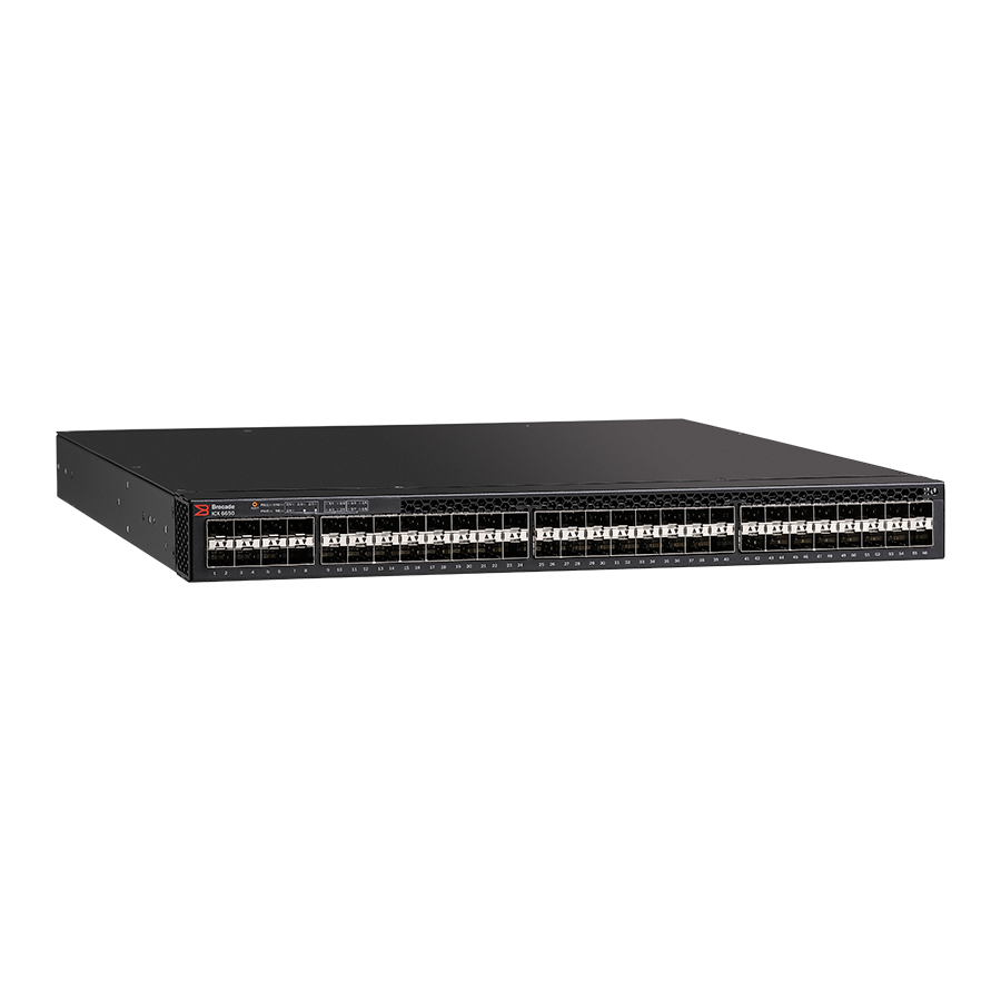
Page 15: Views Of The Brocade Icx 6650 Switch
Ports on Demand license for Brocade ICX 6650, for 8×10 GbE SFP+ ports. ICX6650-2P40G-LIC-POD Ports on Demand license for Brocade ICX 6650, for two QSFP+ (40 GbE or 4×10 GbE) ports. RPS15-E 250 W AC power supply; port-side exhaust airflow. -
Page 16: Ports On Demand Licensing
10. Power supply Ports on Demand licensing The Brocade ICX 6650 features Ports on Demand licensing. With Ports on Demand licensing, software features do not require licenses and you can add port licenses as needed. A fully populated device supports 56 front-panel, dual-speed 1/10 GbE SFP+ ports, 4 rear-panel 40 GbE QSFP+ ports, and 2 rear- panel 4x10 GbE QSFP+ breakout ports. -
Page 17: Brocade Icx 6650 Slot And Ethernet Port Numbering
The Brocade ICX 6650 contains the following slots and Ethernet ports: • Slot 1 is located on the front of the Brocade ICX 6650 switch and contains ports 1 through 56, which are 1/10 GbE SFP+ ports. Refer to the following figure. -
Page 18: Supported Transceivers And Cables
• Slot 2 is located on the rear of the Brocade ICX 6650 switch and contains ports 1 through 3 on the top row and port 4 on the bottom row. These ports are 40 GbE QSFP+ ports. Refer to the following figure. -
Page 19: Breakout Cables
Breakout cables The rear panel of the Brocade ICX 6650 contains two 4 x 10 GbE ports which support QSFP+ to 4 SFP+ (4 x 10 GbE) direct-attach copper breakout cables. These cables are terminated with optical connectors and are available in 1m, 3m, 5m, and greater lengths. No additional connectors or cabling are required for these ports. - Page 20 Cooling system and fans FIGURE 8 Brocade ICX 6650 airflow—front to back (with E-labeled power supply and fan tray) 1. Intake 2. Exhaust FIGURE 9 Exhaust airflow label Brocade ICX 6650 Hardware Installation Guide Part Number: 53-1003621-04...
- Page 21 Cooling system and fans FIGURE 10 Brocade ICX 6650 airflow—back to front (with I-labeled power supply and fan tray) 1. Intake 2. Exhaust FIGURE 11 Intake airflow label Brocade ICX 6650 Hardware Installation Guide Part Number: 53-1003621-04...
- Page 22 Brocade ICX 6650 Hardware Installation Guide Part Number: 53-1003621-04...
-
Page 23: Installing The Brocade Icx 6650
Installing an SFP+ transceiver..................................40 Unpacking the device The Brocade ICX 6650 ships with all of the items listed below. Verify the contents of your shipping container. If any items are missing, contact the place of purchase. Package contents (ICX6650-32-E-ADV, ICX6650-48-E-ADV, and... -
Page 24: Installation And Safety Considerations
• Because the Brocade ICX 6650 can be ordered with fans that move air either front to back or back to front, be sure to orient your switch with the airflow pattern of any other devices in the rack. All equipment in the rack should force air in the same direction to avoid intake of exhaust air. -
Page 25: Cabinet Considerations
TABLE 4 Installation tasks Task number Task Where to find more information Ensure that the physical environment that will Environmental considerations on page 24 host the device has the proper cabling and ventilation. Brocade ICX 6650 Hardware Installation Guide Part Number: 53-1003621-04... -
Page 26: Installation Precautions
Laser Radiation. Do Not View Directly with Optical Instruments. Class 1M Laser Products. DANGER All fiber-optic interfaces use Class 1 lasers. CAUTION Do not install the device in an environment where the operating ambient temperature might exceed 40°C (104°F). Brocade ICX 6650 Hardware Installation Guide Part Number: 53-1003621-04... -
Page 27: Lifting Precautions
Installing the device in a rack or cabinet DANGER Make sure the rack housing the device is adequately secured to prevent it from becoming unstable or falling over. NOTE You need a #2 Phillips screwdriver for installation. Brocade ICX 6650 Hardware Installation Guide Part Number: 53-1003621-04... -
Page 28: 2-Post Rack Mount Installation
NOTE The Brocade ICX 6650 is shipped with a 2-post rack mount kit to mount the switch into 2-post Telco style racks only. If the Brocade ICX 6650 is to be installed into a standard 4-post rack, make sure that you use the correct rack mount kit. - Page 29 Attach the mounting brackets to the sides of the device using the 8-32 x 5/16 in. screws. FIGURE 13 Attaching the mounting brackets for a Brocade ICX 6650 Position the device in the cabinet, providing temporary support under the switch until the rail kit is secured to the cabinet.
-
Page 30: 4-Post Rack Mount Installation
Kits for 4-post rack mounting are not included in the shipping carton and must be ordered separately. NOTE Use the following procedure when installing the Brocade ICX 6650 in a 4-post rack cabinet. For 2-post cabinets, follow the procedures in 2-post rack mount installation on page 28. - Page 31 NOTE Do not use the hardware supplied in a 2-post rack mounting kit to mount a Brocade ICX 6650 in a 4-post rack. Mounting the device in a 4-post rack requires additional hardware to prevent drooping from possible flexing and distortion of the 4-post rack when a device is not properly installed.
- Page 32 Attach the appropriate rails: either side attach or rear attach as determined by the type of rack in which you are installing the device. The following figures show exploded views of the optional 4-post rack mount kit. FIGURE 16 Optional 4-post rack mount kit, rear attachment Brocade ICX 6650 Hardware Installation Guide Part Number: 53-1003621-04...
-
Page 33: Attaching A Pc Or Terminal
Ethernet Switch Administration Guide. Access the CLI by connecting to the console port. After you assign an IP address, you can access the system through Telnet, the Web management interface, or Brocade Network Advisor. Brocade ICX 6650 Hardware Installation Guide Part Number: 53-1003621-04... -
Page 34: Powering On The System
Each Brocade ICX 6650 comes with two alternating-current (AC) power supplies. The Brocade ICX 6650 device also supports direct- current (DC) power supplies. The Brocade ICX 6650 is capable of running on one power supply and one fan. The second set provide redundancy. -
Page 35: Installing And Replacing A Power Supply Unit
Use the following steps to install an AC power supply in the switch. If replacing a power supply, remove the previously installed power supply from the appropriate slot by removing the two screws with a flat-head screwdriver. Brocade ICX 6650 Hardware Installation Guide Part Number: 53-1003621-04... - Page 36 C Temperature Readings: Current temperature : 34.5 deg-C sensor D Temperature Readings: Current temperature : 30.5 deg-C Warning level..: 45.0 deg-C Shutdown level..: 85.0 deg-C Boot Prom MAC : 748e.f893.eabe Management MAC: 748e.f893.eabe Brocade ICX 6650 Hardware Installation Guide Part Number: 53-1003621-04...
-
Page 37: Installing A Dc Power Supply
AC and DC power supplies cannot be installed and used in the same device. Mismatched power supplies in the same device cause continual reboot on power up. FIGURE 19 DC power supply unit You need a #2 Phillips screwdriver and a flat-head screwdriver for installation. Brocade ICX 6650 Hardware Installation Guide Part Number: 53-1003621-04... - Page 38 Before opening the package that contains the DC power supply, touch the bag to the switch casing to discharge any potential static electricity. Remove the DC power supply from the anti-static shielded bag. Brocade ICX 6650 Hardware Installation Guide Part Number: 53-1003621-04...
- Page 39 FIGURE 21 DC power supply wiring assembly 1 Wire tightening screws 2 DC power source wires 3 Earth ground wire 4 Assembly screws Use the wire tightening screws to secure the wires. Brocade ICX 6650 Hardware Installation Guide Part Number: 53-1003621-04...
-
Page 40: Installing An Sfp+ Transceiver
The QSFP+ 40 GbE LR4 optical transceiver is supported in ports 1 and 2 only. When the module is inserted into a stack-unit/slot number/port number combination that is not 1/2/1 or 1/2/2, the following error message displays: “QSFP LR-4 optics not supported on port port-number.” Brocade ICX 6650 Hardware Installation Guide Part Number: 53-1003621-04... - Page 41 SFP+ transceiver in the upper row of ports is with the gold-plated edge down. The correct position to insert an SFP+ transceiver in the lower row of ports is with the gold-plated edge up. FIGURE 23 Installing an SFP+ transceiver in a port slot Brocade ICX 6650 Hardware Installation Guide Part Number: 53-1003621-04...
- Page 42 Brocade ICX 6650 Hardware Installation Guide Part Number: 53-1003621-04...
-
Page 43: Configuring The Brocade Icx 6650
Enter the following command to set the Super User password: device(config)# enable super-user-password text NOTE You must set the Super User password before you can set other types of passwords. Brocade ICX 6650 Hardware Installation Guide Part Number: 53-1003621-04... -
Page 44: Recovering From A Lost Password
Refer to the FastIron Ethernet Switch Administration Guide. Devices running Layer 2 software Use the following procedure to configure an IP address on a device running Layer 2 software. At the opening CLI prompt, enter enable. device> enable Brocade ICX 6650 Hardware Installation Guide Part Number: 53-1003621-04... -
Page 45: Devices Running Layer 3 Software
Devices running Layer 3 software Before attaching equipment to a Brocade ICX 6650, you must assign an interface IP address to the subnet on which the router connected to the switch will be located. You must use the serial connection to assign the first IP address. For subsequent addresses, you also can use the CLI through Telnet or the Web management interface. - Page 46 192.168.0.0 255.255.255.0 You also can enter the IP address and mask in CIDR format, as follows: device(config-if-1/1/1)# ip address 192.168.0.0/24 Syntax: [no] ip address ip-addr ip-mask Syntax: [no] ip address ip-addr/mask-bits Brocade ICX 6650 Hardware Installation Guide Part Number: 53-1003621-04...
-
Page 47: Deleting An Ip Address
This command deletes IP address 1.1.2.1. You do not need to enter the subnet mask. To delete all IP addresses from an interface, enter the following command. device(config-if-1/1/1)# no ip address * Syntax: no ip address ip-addr | * Brocade ICX 6650 Hardware Installation Guide Part Number: 53-1003621-04... -
Page 48: Connecting Network Devices
For direct attachment from the device to a Gigabit NIC, switch, or router, using a fiber-optic transceiver, you need fiber cabling with an LC connector. For information about transceivers supported on the Brocade ICX 6650, refer to the following Brocade website: http://www.myBrocade.com/downloads/documents/data_sheets/product_data_sheets/Optics_DS.pdf To connect the device to another network device using a fiber port, you must perform the following tasks: •... -
Page 49: Testing Connectivity
Test for connectivity by observing the LEDs related to network connection. Pinging an IP address To verify that a Brocade ICX 6650 can reach another device through the network, enter a command similar to the following at any level of the CLI. - Page 50 Web management interface or Brocade Network Advisor. • If the other procedures do not resolve the problem, try using a different port or a different cable. Brocade ICX 6650 Hardware Installation Guide Part Number: 53-1003621-04...
-
Page 51: Brocade Icx 6650 Operation
LEDs do not indicate a healthy state after all boot processes and diagnostic tests are complete. Brocade ICX 6650 front panel LEDs The Brocade ICX 6650 has the following LEDs on the front panel: • Two power supply unit (PSU) bicolor status LEDs (green and amber) labeled PSU1 and PSU2 •... -
Page 52: Brocade Icx 6650 Rear Panel Leds
1/10 GbE port status LEDs Port numbering (odd-numbered port at top, even-numbered port at bottom) Brocade ICX 6650 rear panel LEDs The Brocade ICX 6650 has the following LEDs on the rear panel: • Six 40 GbE QSFP+ port status LEDs (green) •... -
Page 53: Led Patterns
LED patterns FIGURE 25 Brocade ICX 6650 rear panel LEDs and ports Mini-USB connector console port Management port status LEDs 40 GbE ports Ethernet management port 40 GbE port status LEDs LED patterns This section describes the Brocade ICX 6650 LED patterns. -
Page 54: Diag Led
Off (no light) Not enabled. No action required. Blue Link is up in 40 GbE mode. No action required. Blinking blue Indicates activity, and packets are being No action required. transmitted or received. Brocade ICX 6650 Hardware Installation Guide Part Number: 53-1003621-04... -
Page 55: 4X10 Gbe Qsfp+ Rear Port Leds On Front Panel
Brocade ICX 6650 maintenance The Brocade ICX 6650 is designed for high availability and low failure; it does not require any regular physical maintenance. Supported transceivers and diagnostic tests are described in the following sections. Diagnostic tests and monitoring Brocade FastIron software includes diagnostic tests to help you troubleshoot the hardware. - Page 56 Brocade ICX 6650 Hardware Installation Guide Part Number: 53-1003621-04...
-
Page 57: Managing The Brocade Icx 6650
Managing the Brocade ICX 6650 • Managing temperature settings...................................57 • Removing MAC address entries..................................59 • Displaying Brocade ICX 6650 CPU usage............................59 • Hardware maintenance schedule................................59 • Replacing a copper or fiber-optic module.............................. 60 • FRU removal and replacement procedures............................62 •... -
Page 58: Displaying Syslog Messages For Temperature
By default, the software polls the temperature sensor every 60 seconds to get the current temperature. This poll rate is controlled by the device poll time, which also controls how often the software polls other system components. Brocade ICX 6650 Hardware Installation Guide Part Number: 53-1003621-04... -
Page 59: Removing Mac Address Entries
Syntax: show cpu Hardware maintenance schedule Brocade ICX 6650 switch hardware components require minimal maintenance. Brocade recommends cleaning the fiber-optic connectors on a fiber-optic port and the connected fiber cable each time you disconnect the cable. Brocade ICX 6650 Hardware Installation Guide... -
Page 60: Replacing A Copper Or Fiber-Optic Module
Replacing a copper or fiber-optic module Replacing a copper or fiber-optic module You can remove an SFP+ or QSFP+ transceiver from a slot and replace it with a new one while the Brocade ICX 6650 is powered on and running. - Page 61 FIGURE 27 Removing the fiber-optic module Store the copper or fiber-optic module in a safe, static-free place or in an anti-static bag. Install a new copper or fiber-optic module in the port. Brocade ICX 6650 Hardware Installation Guide Part Number: 53-1003621-04...
-
Page 62: Cabling A Fiber-Optic Module
If a mismatched power source or fan assembly is installed by mistake, a warning is sent to the console. The warning messages will be similar to the following: • For a fan mismatch: WARNING, Brocade ICX 6650, MISMATCH in Fan Air Flow direction. Replace FRU with fan air flows in the same direction. •... -
Page 63: Replacing A Power Supply Unit
Changes or modifications made to this device that are not expressly approved by the party responsible for compliance could void the user's authority to operate the equipment. The following table describes the Brocade ICX 6650 power supply status LED colors, behaviors, and actions required, if any. TABLE 11 Power supply status LED behavior, description, and required actions... -
Page 64: Time And Items Required
To display power supply status, you can enter the show chassis command at the command line prompt. To leave the Brocade ICX 6650 in service while replacing a power supply, verify that the other power supply (the one not being replaced) has been powered on for at least four seconds and has a steady green status LED. -
Page 65: Replacing Fan Trays
"E", or an orange arrow with an "I." Orderable Brocade ICX 6650 models include two redundant, hot-swappable fan units. However, it can run on one power supply and one fan. - Page 66 If you do not install a module or a power supply in a slot, you must keep the slot filler panel in place. If you run the chassis with an uncovered slot, the system will overheat. Brocade ICX 6650 Hardware Installation Guide Part Number: 53-1003621-04...
-
Page 67: Brocade Icx 6650 Switch Technical Specifications
Brocade ICX 6650 Switch Technical Specifications This document highlights the features and specifications for the Brocade ICX 6650 switch. System specifications System component Description Enclosure 1U EIA-compliant; power from non-port side; reversible airflow Power inlet Power supplies Two internal, redundant, load-sharing, and hot-swappable power supplies... -
Page 68: Other
4.0 A Line & Neutral 35 A Fused RPS16DC-E 510 W 40-60 VDC 15.5 A Positive Input 40 A Fused RPS16DC-I 510 W 40-60 VDC 15.5 A Positive Input 40 A Fused Brocade ICX 6650 Hardware Installation Guide Part Number: 53-1003621-04... -
Page 69: Power Consumption (Typical Configuration)
Port 4 (bottom row) Serial port specifications (pinout mini-USB) Signal Description Not used UART0_TX Debug port UART0_RX Console port Not used Ground Serial port specifications (protocol) Parameter Value Baud 9600 bps Brocade ICX 6650 Hardware Installation Guide Part Number: 53-1003621-04... -
Page 70: Memory Specifications
2006/66/EC – batteries and accumulators and waste batteries and accumulators (EU battery directive) • 1907/2006 of the European Parliament and of the Council of 18 December 2006 concerning the Registration, Evaluation, Authorisation and Restriction of Chemicals (EU REACH) Brocade ICX 6650 Hardware Installation Guide Part Number: 53-1003621-04... - Page 71 30/2011/TT-BCT – Vietnam circular • SJ/T 11363-2006 Requirements for Concentration Limits for Certain Hazardous Substances in EIPs (China) • SJ/T 11364-2006 Marking for the Control of Pollution Caused by EIPs (China) Brocade ICX 6650 Hardware Installation Guide Part Number: 53-1003621-04...
- Page 72 Brocade ICX 6650 Hardware Installation Guide Part Number: 53-1003621-04...
-
Page 73: Brocade Icx 6650 Regulatory Statements
This Class A digital apparatus meets all requirements of the Canadian Interference-Causing Equipment Regulations, ICES-003 Class A. Cet appareil numérique de la classe A est conforme à la norme NMB-003 du Canada. Brocade ICX 6650 Hardware Installation Guide Part Number: 53-1003621-04... -
Page 74: China Cc Statement
Europe and Australia (CISPR 22 Class A Warning) This is a Class A product. In a domestic environment this product may cause radio interference in which case the user may be required to take adequate measures. Brocade ICX 6650 Hardware Installation Guide Part Number: 53-1003621-04... -
Page 75: Fcc Warning (Us Only)
This is a Class A product based on the standard of the Voluntary Control Council for Interference by Information Technology Equipment (VCCI). If this equipment is used in a domestic environment, radio disturbance might arise. When such trouble occurs, the user might be required to take corrective actions. Brocade ICX 6650 Hardware Installation Guide Part Number: 53-1003621-04... - Page 76 Brocade ICX 6650 Hardware Installation Guide Part Number: 53-1003621-04...
-
Page 77: Brocade Icx 6650 Cautions And Danger Notices
Brocade ICX 6650 Cautions and Danger Notices • Cautions..........................................77 • Danger Notices........................................80 Cautions A Caution statement alerts you to situations that can be potentially hazardous to you or cause damage to hardware, firmware, software, or data. Ein Vorsichthinweis warnt Sie vor potenziellen Personengefahren oder Beschädigung der Hardware, Firmware, Software oder auch vor einem möglichen Datenverlust... - Page 78 Si usted borra accidentalmente la configuración en un sistema ya configurado, introduzca el comando write memory (escribir memoria) para guardar la configuración en ejecución en el archivo startup-config. Brocade ICX 6650 Hardware Installation Guide Part Number: 53-1003621-04...
-
Page 79: Electrical Cautions
Si vous n’installez pas de module ou de bloc d'alimentation dans un slot, vous devez laisser le panneau du slot en place. Si vous faites fonctionner le châssis avec un slot découvert, le système surchauffera. Brocade ICX 6650 Hardware Installation Guide Part Number: 53-1003621-04... -
Page 80: Danger Notices
Ein Gefahrenhinweis warnt vor Bedingungen oder Situationen die tödlich sein können oder Sie extrem gefährden können. Sicherheitsetiketten sind direkt auf den jeweiligen Produkten angebracht um vor diesen Bedingungen und Situationen zu warnen. Brocade ICX 6650 Hardware Installation Guide Part Number: 53-1003621-04... -
Page 81: General Dangers
Débranchez le cordon d'alimentation de toutes les sources d'alimentation pour couper complètement l'alimentation du dispositif. PELIGRO Para desconectar completamente la corriente del instrumento, desconecte el cordón de corriente de todas las fuentes de corriente. Brocade ICX 6650 Hardware Installation Guide Part Number: 53-1003621-04... - Page 82 Das eingeschaltete Gerät darf nicht geöffnet werden, da andernfalls das Risiko eines Stromschlags mit Hochspannung besteht. DANGER Afin d'éviter tout choc électrique, n'ouvrez pas l'appareil lorsqu'il est sous tension. PELIGRO Para evitar una descarga de alto voltaje, no abra el dispositivo mientras esté encendido. Brocade ICX 6650 Hardware Installation Guide Part Number: 53-1003621-04...
-
Page 83: Dangers Related To Equipment Weight
Alle Glasfaser-Schnittstellen verwenden Laser der Klasse 1. DANGER Toutes les interfaces en fibres optiques utilisent des lasers de classe 1. PELIGRO Todas las interfaces de fibra óptica utilizan láser de clase 1. Brocade ICX 6650 Hardware Installation Guide Part Number: 53-1003621-04...
Need help?
Do you have a question about the ICX 6650 and is the answer not in the manual?
Questions and answers