
Related Manuals for Brocade Communications Systems ICX 7250


Summary of Contents for Brocade Communications Systems ICX 7250
- Page 1 HARDWARE INSTALLATION GUIDE Brocade ICX 7250 Switch Hardware Installation Guide 53-1003898-02 15 May 2016...
- Page 2 United States government. The authors and Brocade Communications Systems, Inc. assume no liability or responsibility to any person or entity with respect to the accuracy of this document or any loss, cost, liability, or damages arising from the information contained herein or the computer programs that accompany it.
-
Page 3: Table Of Contents
What's new in this document..............................................11 Supported software..................................................11 Overview........................................................13 Hardware features..................................................13 ICX 7250 models................................................13 Network and management interfaces........................................14 Installation........................................................ 23 Items included with the ICX 7250 device........................................23 Configuration requirements..............................................23 Summary of installation tasks.............................................24 Installation precautions................................................24 General precautions............................................... 24 Lifting precautions................................................24 Power precautions................................................24 Preparing the installation site.............................................. - Page 4 Connecting to workstations, servers, or routers.....................................88 Connecting a network device to a fiber port....................................88 Troubleshooting network connections.......................................... 89 Digital optical monitoring............................................89 Testing connectivity..................................................89 Pinging an IP address..............................................89 Observing LEDs................................................89 Tracing a route..................................................91 Brocade ICX 7250 Switch Hardware Installation Guide 53-1003898-02...
- Page 5 Removing a copper or fiber-optic module......................................97 Installing a fiber-optic transceiver.......................................... 98 Cabling a fiber-optic transceiver..........................................99 Cleaning the fiber-optic connectors........................................100 Cabling a fiber-optic transceiver.............................................100 Brocade ICX 7250 Switch Technical Specifications....................................... 101 System specifications................................................101 Ethernet......................................................101 LEDs........................................................102 Other....................................................... 102 Weight and physical dimensions............................................ 102 Environmental requirements.............................................
- Page 6 Europe and Australia (CISPR 22 Class A Warning)....................................112 FCC warning (US only)................................................113 Germany statement.................................................. 113 KCC statement (Republic of Korea)..........................................113 VCCI statement...................................................113 Cautions and Danger Notices...............................................115 Cautions......................................................115 General cautions................................................115 Electrical cautions................................................116 Danger Notices.................................................... 117 General dangers................................................117 Electrical dangers................................................118 Dangers related to equipment weight........................................
-
Page 7: Preface
In Fibre Channel products, square brackets may be used instead for this purpose. x | y A vertical bar separates mutually exclusive elements. < > Nonprinting characters, for example, passwords, are enclosed in angle brackets. Brocade ICX 7250 Switch Hardware Installation Guide 53-1003898-02... -
Page 8: Notes, Cautions, And Warnings
For product support information and the latest information on contacting the Technical Assistance Center, go to http:// www.brocade.com/services-support/index.html. If you have purchased Brocade product support directly from Brocade, use one of the following methods to contact the Brocade Technical Assistance Center 24x7. Brocade ICX 7250 Switch Hardware Installation Guide 53-1003898-02... -
Page 9: Brocade Oem Customers
By sending your feedback to documentation@brocade.com. Provide the publication title, part number, and as much detail as possible, including the topic heading and page number if applicable, as well as your suggestions for improvement. Brocade ICX 7250 Switch Hardware Installation Guide 53-1003898-02... - Page 10 Preface Brocade ICX 7250 Switch Hardware Installation Guide 53-1003898-02...
-
Page 11: About This Document
Installing the 1U, 1.5U, and 2U Universal Kit for Four Post Racks (XBR-R000295) on page 29 Installing the Universal Four-Post Rack Kit (XBR-R000296) on page 43. Supported software This document is specific to the Brocade ICX 7250 running FastIron release 08.0.40 and later. Brocade ICX 7250 Switch Hardware Installation Guide 53-1003898-02... - Page 12 About This Document Brocade ICX 7250 Switch Hardware Installation Guide 53-1003898-02...
-
Page 13: Overview
Hardware features..........................................13 Hardware features The following sections describe the physical characteristics of the devices. ICX 7250 models The Brocade ICX 7250 Ethernet switch is available in the models listed in the following table. TABLE 1 ICX 7250 models Model Description... -
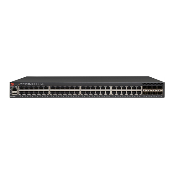
Page 14: Network And Management Interfaces
USB port NOTE 24-port devices have similar front panels. For the ICX 7250-24G, the slot 2 ports are SFP ports. Brocade ICX 7250 Switch Hardware Installation Guide 53-1003898-02... -
Page 15: Console Management Interface
(data) ports. These ports support 1 Gbps but not 10 Gbps port speeds. All other Brocade ICX 7250 devices contain eight SFP+ ports that support 1 Gbps or 10 Gbps port speeds. The top row ports are odd numbered (ports 1, 3, 5, and 7) and the bottom row ports are even numbered (ports 2, 4, 6, and 8). All ports can be used for stacking or uplinking. -
Page 16: Specifying A Port Address
The devices include LEDs that indicate the status of device components. NOTE The following figures show examples of the port status LEDs for similar ports are present for models with a higher number of ports. Brocade ICX 7250 Switch Hardware Installation Guide 53-1003898-02... - Page 17 PoE/PoE+ LEDs for corresponding ports NOTE The PoE/PoE+ LEDs are reserved on models that do not support PoE or PoE+ operation. FIGURE 7 Port status LEDs for SFP or SFP+ ports SFP or SFP+ ports Brocade ICX 7250 Switch Hardware Installation Guide 53-1003898-02...
- Page 18 1 Gbps. A link is not established with a remote port. SFP+ (X1 - X8) for all other ICX 7250 devices On/Flashing Green The SFP+ port is operating at 10 Gbps. Flashing indicates the port is transmitting and receiving user packets at 10 Gbps.
- Page 19 Overview System status LEDs The following figure shows the system status LEDs for ICX 7250 models. FIGURE 9 System status LEDs for ICX 7250 models ICX 7250-24G LEDs ICX 7250-24, ICX 7250-24P, ICX 7250-48 LEDs ICX 7250-48P LEDs TABLE 4 System status LEDs...
-
Page 20: Power Supplies
DC power to the device in the event the internal power supply fails or for supplemental power for PoE or PoE+ applications. The following figure shows an example of a typical rear panel for an ICX 7250 device. FIGURE 10 ICX 7250 power supply connectors... -
Page 21: Power Supply Usage
Brocade ICX 7250-48 Brocade ICX 7250-48P Power supply usage The Brocade ICX 7250 models support specific AC power supply inputs and a number of PoE and PoE+ ports with an internal power supply. NOTE Depending on the configuration, each EPS4000 connection from the device to the EPS4000 can add 24 ports of PoE (Class 3) or 12 ports of PoE+ power (54-volt supply) in addition to the internal power supply by providing system power backup. - Page 22 Overview Brocade ICX 7250 Switch Hardware Installation Guide 53-1003898-02...
-
Page 23: Installation
Items included with the ICX 7250 device ICX 7250 devices ship with all of the following items included in your shipping container. Verify the contents of your shipping container. If any items are missing, contact the place of purchase. -
Page 24: Summary Of Installation Tasks
25 host the device has the proper cabling and ventilation. Unpack the device and all included accessories. Items included with the ICX 7250 device page 23 Install the device on a desktop, or in an Installing the device on page 26 equipment rack. -
Page 25: Preparing The Installation Site
Temperature: Because the temperature within a rack assembly may be higher than the ambient room temperature, check that the rack-environment temperature is within the specified operating temperature range. Refer to Brocade ICX 7250 Switch Technical Specifications on page 101. Brocade ICX 7250 Switch Hardware Installation Guide 53-1003898-02... -
Page 26: Installing The Device
Mount the devices you install in a rack as low as possible. Place the heaviest device at the bottom and progressively place lighter devices above. Desktop installation Complete the following steps to install the ICX 7250 device on a desktop or other flat surface. The device you are installing might look different than the one in the following illustration. DANGER This equipment is suitable for mounting on concrete or other noncombustible surfaces only. -
Page 27: Installing The Device Into A Rack
This section describes the procedures you use to mount the device into a rack. The Brocade ICX 7250 can be installed in a 2-post or 4-post rack. The device ships with a 2-post rack. To use the rack that ships with the product, refer to... - Page 28 The #6-32 sink-head screws are for front-mounting. Use the #8-32 screws for rear-mounting. FIGURE 12 Attaching the rack mounting brackets for the ICX 7250 Remove the two-post rack kit from the shipping carton. The kit contains four rack-mounting screws and four cage nuts.
- Page 29 24 in. (609.60 mm) and a maximum distance of 32 in. (812.80 mm) between the front and back posts. Time and items required Allow 15 to 30 minutes to complete this procedure. Note the following requirements to ensure correct installation and operation. Brocade ICX 7250 Switch Hardware Installation Guide 53-1003898-02...
- Page 30 Use the screws specified in the procedure. Using longer screws can damage the device. Parts list The following parts are provided with the 1U, 1.5U, and 2U Universal Kit for Four Post Racks Installation (XBR-R000296). Brocade ICX 7250 Switch Hardware Installation Guide 53-1003898-02...
- Page 31 Complete the following tasks to install the device in a four-post rack: Attaching the front brackets on page 46 Attaching the extension brackets to the device on page 47 Installing the device in the rack on page 48 Brocade ICX 7250 Switch Hardware Installation Guide 53-1003898-02...
- Page 32 Tighten all the 8-32 x 5/16-in. screws to a torque of 15 in-lb (17 cm-kg). FIGURE 15 Attaching the front brackets Device Front brackets Screws, 8-32 x 5/16-in., flathead Phillips Brocade ICX 7250 Switch Hardware Installation Guide 53-1003898-02...
- Page 33 Complete the following steps to install the device in the rack. Position the device in the rack, as shown in Figure 17, providing temporary support under the device until the rail kit is secured to the rack. Brocade ICX 7250 Switch Hardware Installation Guide 53-1003898-02...
- Page 34 Attach the brackets using four 6-32 x 1/4-in. panhead screws. Repeat Step 2 Step 3 to attach the left rear bracket to the left extension. Brocade ICX 7250 Switch Hardware Installation Guide 53-1003898-02...
- Page 35 Adjust the brackets to the rack depth and tighten all the 6-32 x 1/4-in. screws to a torque of 9 in-lb (10 cm-kg). FIGURE 18 Attaching the rear brackets to the extensions Rear brackets Screws, 6-32 x 1/4-in., panhead Phillips Brocade ICX 7250 Switch Hardware Installation Guide 53-1003898-02...
- Page 36 Attach the left rear bracket to the left rear rack post using two 10-32 x 5/8-in. panhead screws and two retainer nuts. Use the upper and lower holes in the bracket. Tighten all the 10-32 x 5/8-in. screws to a torque of 25 in-lb (29 cm-kg). Brocade ICX 7250 Switch Hardware Installation Guide 53-1003898-02...
- Page 37 Installing the device in the rack on page 53 Attaching the rear brackets to the extensions at the front of the device on page 54 Attaching the rear brackets to the front rack posts on page 56 Brocade ICX 7250 Switch Hardware Installation Guide 53-1003898-02...
- Page 38 Tighten all the 8-32 x 5/16-in. screws to a torque of 15 in-lb (17 cm-kg). FIGURE 21 Attaching the front brackets to the rear of the device Device Screws, 8-32 x 5/16-in., flathead Phillips Front brackets Brocade ICX 7250 Switch Hardware Installation Guide 53-1003898-02...
- Page 39 Attach the right front bracket to the right rear rack post using two 10-32 x 5/8-in. panhead screws and two retainer nuts. Use the upper and lower holes in the bracket. Brocade ICX 7250 Switch Hardware Installation Guide 53-1003898-02...
- Page 40 Adjust the brackets to the rack depth and tighten all the 6-32 x 1/4-in. screws to a torque of 9 in-lb (10 cm-kg). Brocade ICX 7250 Switch Hardware Installation Guide 53-1003898-02...
- Page 41 Installation FIGURE 24 Attaching the rear brackets to the extensions at the front of the device Rear brackets, short Screws, 6-32 x 1/4-in., panhead Phillips Brocade ICX 7250 Switch Hardware Installation Guide 53-1003898-02...
- Page 42 Attach the left rear bracket to the left front rack post using two 10-32 x 5/8-in. screws and two retainer nuts. Use the upper and lower holes in the bracket. Tighten all the 10-32 x 5/8-in. screws to a torque of 25 in-lb (29 cm-kg). Brocade ICX 7250 Switch Hardware Installation Guide 53-1003898-02...
- Page 43 Although this document describes how to install both single height (1U) and double height (2U) switches, the illustrations show a 1U switch as a typical installation. NOTE Hardware devices illustrated in these procedures are only for reference and may not depict the device you are installing into the rack. Brocade ICX 7250 Switch Hardware Installation Guide 53-1003898-02...
- Page 44 Allow 15 to 30 minutes to complete the installation. The following items are required to install the device using the Universal Four-Post Rack Kit: ∙ #2 Phillips torque screwdriver ∙ 1/4-inch slotted-blade torque screwdriver Brocade ICX 7250 Switch Hardware Installation Guide 53-1003898-02...
- Page 45 Note that not all parts may be used with certain installations depending on the device type. CAUTION Use the screws specified in the procedure. Using longer screws can damage the device. Brocade ICX 7250 Switch Hardware Installation Guide 53-1003898-02...
- Page 46 Repeat step 1 and step 2 to attach the left front bracket to the left side of the device. Tighten all the 8-32 x 5/16-in. screws to a torque of 15 in-lb (17 cm-kg). Brocade ICX 7250 Switch Hardware Installation Guide 53-1003898-02...
- Page 47 Repeat step 1 and step 2 to attach the left extension bracket to the left side of the device. Tighten all the 8-32 x 5/16-in. screws to a torque of 15 in-lb (17 cm-kg). Brocade ICX 7250 Switch Hardware Installation Guide 53-1003898-02...
- Page 48 Attach the left front bracket to the left front rack post using two 10-32 x 5/8-in. panhead screws and two retainer nuts. Use the upper and lower holes in the bracket. Tighten all the 10-32 x 5/8-in. screws to a torque of 25 in-lb (29 cm-kg). Brocade ICX 7250 Switch Hardware Installation Guide 53-1003898-02...
- Page 49 Repeat step 2 to attach the left rear bracket to the left extension. Adjust the brackets to the rack depth and tighten all the 6-32 x 1/4-in. screws to a torque of 9 in-lb (10 cm-kg). Brocade ICX 7250 Switch Hardware Installation Guide 53-1003898-02...
- Page 50 Attach the left rear bracket to the left rear rack post using two 10-32 x 5/8-in. panhead screws and two retainer nuts. Use the upper and lower holes in the bracket. Tighten all the 10-32 x 5/8-in. screws to a torque of 25 in-lb (29 cm-kg). Brocade ICX 7250 Switch Hardware Installation Guide 53-1003898-02...
- Page 51 Attaching the front brackets to the rear of the device NOTE In this installation, the brackets are named as listed in the parts list even though the installation of the brackets is reversed from the flush-front installation. Brocade ICX 7250 Switch Hardware Installation Guide 53-1003898-02...
- Page 52 Repeat step 1 and step 2 to attach the left front extension to the left side of the device. Tighten all the 8-32 x 5/16-in. screws to a torque of 15 in-lb (17 cm-kg). Brocade ICX 7250 Switch Hardware Installation Guide 53-1003898-02...
- Page 53 Attach the left front bracket to the left rear rack post using two 10-32 x 5/8-in. panhead screws and two retainer nuts. Use the upper and lower holes in the bracket. Tighten all the 10-32 x 5/8-in. screws to a torque of 25 in-lb (29 cm-kg). Brocade ICX 7250 Switch Hardware Installation Guide 53-1003898-02...
- Page 54 Repeat step 2 and step 3 to attach the left rear bracket to the left extension. Adjust the brackets to the rack depth and tighten all the 6-32 x 1/4-in. screws to a torque of 9 in-lb (10 cm-kg). Brocade ICX 7250 Switch Hardware Installation Guide 53-1003898-02...
- Page 55 Installation FIGURE 36 Attaching the rear brackets to the extensions at the front of the device Rear brackets, short Screws, 6-32 x 1/4-in., panhead Phillips Brocade ICX 7250 Switch Hardware Installation Guide 53-1003898-02...
- Page 56 Attach the left rear bracket to the left front rack post using two 10-32 x 5/8-in. screws and two retainer nuts. Use the upper and lower holes in the bracket. Tighten all the 10-32 x 5/8-in. screws to a torque of 25 in-lb (29 cm-kg). Brocade ICX 7250 Switch Hardware Installation Guide 53-1003898-02...
-
Page 57: Wall Mount Installation
Attach the four adhesive feet to the bottom of the device. Using a Phillips screwdriver, attach the wall mount brackets to the sides of the device using four #6-32 sink-head screws on each side. Brocade ICX 7250 Switch Hardware Installation Guide 53-1003898-02... - Page 58 Drill two holes on the wall where you want to mount the device. Hammer two wall mount anchors into the holes on the wall. Use the two wall mount screws to fasten the device to the wall mount anchors. Brocade ICX 7250 Switch Hardware Installation Guide 53-1003898-02...
-
Page 59: Connecting Devices In A Traditional Stack
Stacking ports and trunks There are eight SFP+ ports on the front panels of the ICX 7250 devices that support stacking, which can be used as uplink (data) ports or as stacking ports. The following figure shows the ports in slot 2; the top row consists of ports 1, 3, 5, and 7, and the bottom row... -
Page 60: Stacking Configuration Requirements
Traditional stack size A traditional stack can contain a maximum of twelve ICX 7250 devices. Stacking topologies for a traditional stack Both linear and ring topologies are supported in a traditional stack. In a linear stack topology there is a connection between each switch that carries two-way communications across the stack. - Page 61 In a ring stacking topology, there is an extra connection between the logical first and last devices, forming a "ring" or "closed-loop." The closed-loop connection provides a redundant path for the stack link, so if one link fails, stack communications can be maintained. FIGURE 43 Ring stacking topology First device in stack Brocade ICX 7250 Switch Hardware Installation Guide 53-1003898-02...
-
Page 62: Powering On The System
Attach the AC power cord to the AC connector on the rear panel. Insert the power cord plug into a 100V-240V outlet. NOTE To turn the system off, simply unplug the power cord or cords. Brocade ICX 7250 Switch Hardware Installation Guide 53-1003898-02... -
Page 63: Installing The Eps4000
The primary source of 12 V power for an ICX 7250 device is the internal power supply. The EPS4000 is designed to serve primarily as a backup source of 12 V power. You should service a failed ICX 7250 device as soon as possible after a 12 V power failure is detected. -
Page 64: Eps4000 Features And Benefits
DC for use by the switches. NOTE The internal power supply of the ICX 7250 devices is not a field-replaceable unit (FRU). The devices must be shut down by administrators for replacement. Brocade recommends that you pay attention to the PoE or PoE+ port configuration of the device when connecting to an EPS4000. The internal power supply of each PoE or PoE+ device has a maximum number of supported PoE or PoE+ ports. - Page 65 10. Out-of-band, Ethernet management port (RJ-45) FIGURE 45 EPS4000 rear panel DC power cable connector 1 DC power cable connector 2 DC power cable connector 3 DC power cable connector 4 DC power cable connector 5 Brocade ICX 7250 Switch Hardware Installation Guide 53-1003898-02...
-
Page 66: Leds
R1.1 ~ R8.1 (12 V1) No connection. Green Switch is connected to this channel and EPS is ready to provide 12 V backup power for R1.2 ~ R8.2 (12 V2) this channel. Brocade ICX 7250 Switch Hardware Installation Guide 53-1003898-02... -
Page 67: Items Included With The Eps4000
China ROHS sheet ∙ Read Me First document Configuration requirements The configuration requirements for the EPS4000 are the same as the for the ICX 7250. Refer to Configuration requirements on page Summary of installation tasks Follow the steps in the following table to install your device. Details for each of these steps are provided on the pages indicated. -
Page 68: Installation Precautions
The maximum ampere ratings are usually printed on the devices near the input power connectors. DANGER Disconnect the power cord from all power sources to completely remove power from the device. Brocade ICX 7250 Switch Hardware Installation Guide 53-1003898-02... -
Page 69: Preparing The Installation Site
You can install the device on a desktop or in an equipment rack. DANGER Mount the devices you install in a rack as low as possible. Place the heaviest device at the bottom and progressively place lighter devices above. Brocade ICX 7250 Switch Hardware Installation Guide 53-1003898-02... -
Page 70: Desktop Installation
Mounting an external power supply in a rack (two-post) DANGER Make sure the rack housing the device is adequately secured to prevent it from becoming unstable or falling over. Brocade ICX 7250 Switch Hardware Installation Guide 53-1003898-02... - Page 71 FIGURE 48 Attaching the mounting brackets to the device Mount the external power supply in a rack using four rack-mounting screws. Use the four cage nuts to screw the device to the rack mount holes. Brocade ICX 7250 Switch Hardware Installation Guide 53-1003898-02...
-
Page 72: Installing An Rps17 Psu
While installing a PSU, wear an ESD wrist strap. DANGER For safety reasons, the ESD wrist strap should contain a series 1 megaohm resistor. Perform the following steps to install an RPS17 PSU. Brocade ICX 7250 Switch Hardware Installation Guide 53-1003898-02... -
Page 73: Uninstalling An Rps17 Psu
Put on the ESD wrist strap and ground yourself by attaching the clip end to a metal surface (such as an equipment rack) to act as ground. Lift the PSU latch and gently slide the PSU out from the slot. Brocade ICX 7250 Switch Hardware Installation Guide 53-1003898-02... -
Page 74: Connecting The Eps4000 Cord
370 W at 54 V to each of two switches from one port on the EPS4000 power supply. Both cords deliver up to 120 W at 12 V. You must use a 1:2 cord if you want an ICX 7250-48P device to share 54-V power with another device. Both 1:1 and 1:2 cords will deliver only 370 W of 54 V power to an ICX 7250-24P device. - Page 75 Complete the following steps to connect the EPS4000 cord. CAUTION Do not use the cable to connect two EPS4000 ports. NOTE You can connect either end of the cable first. Hot insertion is supported for cable installation. Brocade ICX 7250 Switch Hardware Installation Guide 53-1003898-02...
-
Page 76: Powering On The System
The device shown in the diagram may be different from the one you are using. The process to remove the EPS4000 faceplate is the same. FIGURE 53 Removing the EPS4000 faceplate on the ICX 7250 device Faceplate screws Using a Phillips screwdriver, remove the two screws on the EPS4000 faceplate of the external power receptacle. -
Page 77: Verifying Proper Operation
1U; 19-inch rack-mountable or desktop Power inlet C14 for AC power Power outlet Custom connector for DC power to all ICX 7250 devices except ICX 7250-24G Power supply unit (PSU) Up to four RPS17, field-replaceable units (FRU) Fans One fan per installed RPS17... -
Page 78: Management
2.4 G sine, 1.1 gms random, 5-500 Hz Heat dissipation Refer to RPS17 specification section in Brocade ICX 7250 Switch Technical Specifications on page 101 Operating noise Single PSU installed: 46.5 to 48.3 dBA Brocade ICX 7250 Switch Hardware Installation Guide 53-1003898-02... -
Page 79: Regulatory Compliance (Emc)
∙ 30/2011/TT-BCT - Vietnam circular ∙ SJ/T 11363-2006 Requirements for Concentration Limits for Certain Hazardous Substances in EIPs (China) ∙ SJ/T 11364-2006 Marking for the Control of Pollution Caused by EIPs (China) Brocade ICX 7250 Switch Hardware Installation Guide 53-1003898-02... - Page 80 Installing the EPS4000 Brocade ICX 7250 Switch Hardware Installation Guide 53-1003898-02...
-
Page 81: Danger
To connect the console port to a DB9 port, you need a cable with mini-USB and DB9 connectors. For information about locating the serial port, refer to Network and management interfaces on page 14. Brocade ICX 7250 Switch Hardware Installation Guide 53-1003898-02... -
Page 82: Password Assignment
Super User: Allows complete read-and-write access to the system. This is generally for system administrators and is the only password level that allows you to configure passwords. NOTE You must set a Super User password before you can set other types of passwords. Brocade ICX 7250 Switch Hardware Installation Guide 53-1003898-02... -
Page 83: Assigning Passwords
Depending on the device you purchased, and the code (Layer 2 or Layer 3) loaded on your system, the router prompt is displayed accordingly. For example, for an ICX 7250-48P device running Layer 3 code on the device, the router prompt displays ICX 7250-48P Router>... -
Page 84: Ip Address Configuration
By default, you can configure up to 24 IP interfaces on each port, virtual interface, and loopback interface. You can increase this amount to up to 64 IP subnet addresses per port by increasing the size of the subnet-per-interface table. Brocade ICX 7250 Switch Hardware Installation Guide 53-1003898-02... - Page 85 VLAN. Instead, you must configure the parameters on the virtual routing interface itself. Assigning an IP address to an Ethernet port Enter the following commands to assign an IP address to port 1/1/1. device(config)# interface ethernet 1/1/1 device(config)# ip address 10.45.6.1 255.255.255.0 Brocade ICX 7250 Switch Hardware Installation Guide 53-1003898-02...
-
Page 86: Deleting An Ip Address
This command deletes IP address 10.1.2.1. You do not need to enter the subnet mask. To delete all IP addresses from an interface, enter the following command. device(config-if-1/1/1)# no ip address * Brocade ICX 7250 Switch Hardware Installation Guide 53-1003898-02... -
Page 87: Connecting Network Devices
1000Base-T ports. In this case, a straight-through cable may work just as well as a crossover cable. For more information, refer to the FastIron Ethernet Switch Administration Guide . FIGURE 54 UTP crossover cable Brocade ICX 7250 Switch Hardware Installation Guide 53-1003898-02... -
Page 88: Connecting To Workstations, Servers, Or Routers
For instructions on cabling a fiber-optic transceiver, refer to Cabling a fiber-optic transceiver on page 99. For instructions on cleaning a fiber-optic module, refer to Cleaning the fiber-optic connectors on page 100. Brocade ICX 7250 Switch Hardware Installation Guide 53-1003898-02... -
Page 89: Troubleshooting Network Connections
If the other procedures do not resolve the problem, try using a different port or a different cable. ∙ If a 1-Gbps optic transceiver is inserted into an ICX 7250 device, you must configure the port using the speed-duplex 1000- full-master command at the interface level. - Page 90 ∙ Dust may have accumulated in the cable connector or port connector. For information about cleaning the connectors, refer to Cleaning the fiber-optic connectors on page 100. Brocade ICX 7250 Switch Hardware Installation Guide 53-1003898-02...
-
Page 91: Tracing A Route
The CLI displays trace route information for each hop as soon as the information is received. Traceroute requests display all responses to a given TTL. In addition, if there are multiple equal-cost routes to the destination, the Brocade device displays up to two responses by default. Brocade ICX 7250 Switch Hardware Installation Guide 53-1003898-02... - Page 92 Configuring the Device Brocade ICX 7250 Switch Hardware Installation Guide 53-1003898-02...
-
Page 93: Managing An Icx 7250 Device
NOTE In addition to the overall temperature of the module, the ICX 7250-24P and ICX 7250-48P modules monitor the temperature of the Power Over Ethernet (PoE) power supply unit (PSU). When the low limit and high limit temperatures are reached, the PoE PSU fans change speed using the same algorithm as the module fans. -
Page 94: Fan Detection And Error Checking Policies
(refer to the following table). If the Brocade ICX 7250 determines that there is a problem with the fans, it performs the following actions and generates the following syslog messages, as shown in the following table. -
Page 95: Displaying The Temperature
To change the temperature at which the device sends a syslog message and an SNMP trap, enter the temperature warning value command at the privileged EXEC level of the CLI. device# temperature warning 1 82 stack-id variable can be a value from 1 through 12. Brocade ICX 7250 Switch Hardware Installation Guide 53-1003898-02... -
Page 96: Changing The Temperature Poll Time
MAC addresses for a specified Ethernet port. Use the clear mac-address ethernet Use the clear mac-address vlan number command to remove all MAC addresses for a specified VLAN. Brocade ICX 7250 Switch Hardware Installation Guide 53-1003898-02... -
Page 97: Hardware Maintenance Schedule
Removing a copper or fiber-optic module You can remove a copper or fiber SFP or SFP+ transceiver from a slot while the ICX 7250 device is powered on and running. While removing a copper or fiber-optic module, be sure to wear an ESD wrist strap with a plug that can be inserted in the ESD connector on the ICX 7250 device. -
Page 98: Installing A Fiber-Optic Transceiver
You can install a new fiber-optic transceiver in an SFP or SFP+ slot while the device is powered on and running. While installing a transceiver, wear an ESD wrist strap with a plug that can be inserted in the ESD connector on the ICX 7250 device. -
Page 99: Cabling A Fiber-Optic Transceiver
Gently insert the cable connector (a tab on each connector should face upward) into the transceiver connector until the tabs lock into place. Observe the link and active LEDs to determine if the network connections are functioning properly. For more information about the LED indicators, refer to Observing LEDs on page 89. Brocade ICX 7250 Switch Hardware Installation Guide 53-1003898-02... -
Page 100: Cleaning The Fiber-Optic Connectors
Gently insert the cable connector (a tab on each connector should face upward) into the transceiver connector until the tabs lock into place. Observe the link and active LEDs to determine if the network connections are functioning properly. For more information about the LED indicators, refer to Observing LEDs on page 89. Brocade ICX 7250 Switch Hardware Installation Guide 53-1003898-02... -
Page 101: Brocade Icx 7250 Switch Technical Specifications
Integrated AC power supply for system and PoE power External AC power supply (EPS4000) for redundant system power and extended PoE/PoE+ power (not applicable to the ICX 7250-24G). DC power supplied to the switches depends on the EPS4000 configuration. Fans... -
Page 102: Leds
The following LEDs are not available on the ICX 7250-24G. EPS1: Bicolor LED (green/amber) indicates if the external power supply (EPS1) is operating normally EPS2 (available only on the ICX 7250-48P): Bicolor LED (green/amber) indicates if the external power supply (EPS2) is operating normally... -
Page 103: Environmental Requirements
Power supply specifications (per PSU) The EPS4000 and its power supply modules (RPS17) are field-replaceable. All other Brocade ICX 7250 power supply units (PSUs) are fixed and internal to the devices. All the PSUs use a C14 inlet and connect to standard AC power. -
Page 104: Power Consumption (Idle Configuration)
Power consumption (idle configuration) Idle: No optics or connections to ports installed and system booted up. Fans at nominal speed. NOTE The Brocade ICX 7250 does not support -48 VDC input power. Model name @100 VAC input @200 VAC input... -
Page 105: Power Consumption (Typical Configuration)
Typical: 10% traffic rate on all ports with 64-byte packet size and random payload at room temperature. All ports fully configured. Fans at nominal speed. NOTE The Brocade ICX 7250 does not support -48 VDC input power. Model name @100 VAC input... -
Page 106: Data Port Specifications (Ethernet)
Uplink or stacking SFP+ ports Serial port specifications (pinout mini-USB) Signal Description Reserved Not used UART_RX Receive data by Brocade ICX 7250 UART_TX Transmit data by Brocade ICX 7250 Reserved Not used Logic ground Brocade ICX 7250 Switch Hardware Installation Guide 53-1003898-02... -
Page 107: Serial Port Specifications (Protocol)
EN 60950/IEC 60950 Safety of Information Technology Equipment Regulatory compliance (environmental) ∙ 2014/35/EU and 2014/30/EU ∙ 2011/65/EU - Restriction of the use of certain hazardous substance in electrical and electronic equipment (EU RoHS). Brocade ICX 7250 Switch Hardware Installation Guide 53-1003898-02... - Page 108 ∙ 30/2011/TT-BCT - Vietnam circular. ∙ SJ/T 11363-2006 Requirements for Concentration Limits for Certain Hazardous Substances in EIPs (China). ∙ SJ/T 11364-2006 Marking for the Control of Pollution Caused by EIPs (China). Brocade ICX 7250 Switch Hardware Installation Guide 53-1003898-02...
-
Page 109: Troubleshooting
However, you must first configure the device with a valid IP address, subnet mask, and default gateway. If you have trouble establishing a link to the management agent, check to see if you have a valid network connection. Then verify that you Brocade ICX 7250 Switch Hardware Installation Guide 53-1003898-02... - Page 110 IP address. Also, be sure the port through which you are connecting to the device has not been disabled. If it has not been disabled, then check the network cabling that runs between your remote location and the device. Brocade ICX 7250 Switch Hardware Installation Guide 53-1003898-02...
-
Page 111: Regulatory Statements
Refer to the latest revision of the China ROHS document (P/N 53‐1000428‐xx) which ships with the product. BSMI statement (Taiwan) Warning: This is Class A product. In a domestic environment this product may cause radio interference in which case the user may be required to take adequate measures. Brocade ICX 7250 Switch Hardware Installation Guide 53-1003898-02... -
Page 112: Canadian Requirements
Europe and Australia (CISPR 22 Class A Warning) This is a Class A product. In a domestic environment this product may cause radio interference in which case the user may be required to take adequate measures. Brocade ICX 7250 Switch Hardware Installation Guide 53-1003898-02... -
Page 113: Fcc Warning (Us Only)
This is a Class A product based on the standard of the Voluntary Control Council for Interference by Information Technology Equipment (VCCI). If this equipment is used in a domestic environment, radio disturbance might arise. When such trouble occurs, the user might be required to take corrective actions. Brocade ICX 7250 Switch Hardware Installation Guide 53-1003898-02... - Page 114 Regulatory Statements Brocade ICX 7250 Switch Hardware Installation Guide 53-1003898-02...
-
Page 115: Cautions And Danger Notices
8 cm sur chaque côté. PRECAUCIÓN Asegúrese de proporcionar una ventilación adecuada al sistema. Se recomienda dejar 3 cm de espacio libre por encima del dispositivo y 8 cm a cada lado. Brocade ICX 7250 Switch Hardware Installation Guide 53-1003898-02... -
Page 116: Electrical Cautions
Nennstromleistung (in Ampere) aller Geräte, die am selben Stromkreis wie das Gerät installiert sind. Somit können Sie feststellen, ob die Gefahr einer Überbelastung der Versorgungsstromkreise vorliegt. Vergleichen Sie diese Summe mit der Nennstromgrenze des Stromkreises. Die Höchstnennströme (in Ampere) stehen normalerweise auf der Geräterückseite neben den Eingangsstromanschlüssen. Brocade ICX 7250 Switch Hardware Installation Guide 53-1003898-02... -
Page 117: Danger Notices
Una advertencia de peligro indica condiciones o situaciones que pueden resultar potencialmente letales o extremadamente peligrosas. También habrá etiquetas de seguridad pegadas directamente sobre los productos para advertir de estas condiciones o situaciones. General dangers DANGER The procedures in this manual are for qualified service personnel. Brocade ICX 7250 Switch Hardware Installation Guide 53-1003898-02... -
Page 118: Electrical Dangers
Falls für die Installation ein anderes Stromkabel erforderlich ist (wenn das mit dem Gerät gelieferte Kabel nicht passt), müssen Sie sicherstellen, dass Sie ein Stromkabel mit dem Siegel einer Sicherheitsbehörde verwenden, die für die Zertifizierung von Brocade ICX 7250 Switch Hardware Installation Guide 53-1003898-02... -
Page 119: Dangers Related To Equipment Weight
Alle Glasfaser-Schnittstellen verwenden Laser der Klasse 1. DANGER Toutes les interfaces en fibres optiques utilisent des lasers de classe 1. PELIGRO Todas las interfaces de fibra óptica utilizan láser de clase 1. Brocade ICX 7250 Switch Hardware Installation Guide 53-1003898-02...
Need help?
Do you have a question about the ICX 7250 and is the answer not in the manual?
Questions and answers