Brocade Communications Systems ICX 7450 Hardware Installation Manual
Supporting fastiron software release 08.0.30
Hide thumbs
Also See for ICX 7450:
- Hardware installation manual (84 pages) ,
- Deployment manual (83 pages) ,
- Configuration manual (593 pages)

Subscribe to Our Youtube Channel
Related Manuals for Brocade Communications Systems ICX 7450


Summary of Contents for Brocade Communications Systems ICX 7450
-
Page 1: Hardware Installation Guide
53-1003623-03 ® 10 October 2016 Brocade ICX 7450 Hardware Installation Guide Supporting FastIron Software Release 08.0.30... - Page 2 Export of technical data contained in this document may require an export license from the United States government. The authors and Brocade Communications Systems, Inc. shall have no liability or responsibility to any person or entity with respect to any loss, cost, liability, or damages arising from the information contained in this book or the computer programs that accompany it.
-
Page 3: Table Of Contents
In this chapter ..........1 Brocade ICX 7450 features ....... . . 1 Brocade ICX 7450 customizable switches . - Page 4 Brocade ICX 7450 front panel LEDs ......35 Brocade ICX 7450 rear panel LEDs ......41 LED patterns .
- Page 5 USA (FCC CFR 47 Part 15 Warning) ......67 Brocade ICX 7450 Hardware Installation Guide...
- Page 6 Appendix C Brocade ICX 7450 Cautions and Danger Notices In this appendix ......... . 71 Cautions.
-
Page 7: About This Guide
IP, RIP, OSPF, BGP, IS-IS, PIM, and VRRP. Supported hardware and software This document is specific to the Brocade ICX 7450 running FastIron release 08.0.20a. How this document is organized The document contains the following components: •... -
Page 8: Text Formatting
The following notices and statements are used in this manual. They are listed below in order of increasing severity of potential hazards. NOTE A note provides a tip, guidance, or advice, emphasizes important information, or provides a reference to related information. viii Brocade ICX 7450 Hardware Installation Guide 53-1003623-02... -
Page 9: Notice To The Reader
The following Brocade documents supplement the information in this guide: • Brocade ICX 7450 Release Notes • Brocade ICX 7450 Administration Guide • Brocade ICX 7450 Platform and Layer 2 Configuration Guide • Brocade ICX 7450 Layer 3 Routing Configuration Guide • Brocade ICX 7450 Security Configuration Guide •... -
Page 10: Additional Information
Forward your feedback to: documentation@brocade.com Provide the title and version number of the document and as much detail as possible about your comment, including the topic heading and page number and your suggestions for improvement. Brocade ICX 7450 Hardware Installation Guide 53-1003623-02... -
Page 11: Chapter 1 Brocade Icx 7450 Overview
• Views of the Brocade ICX 7450 switch....... 4 •... - Page 12 RPS16DC-I Brocade ICX 510 W DC PSU, power-supply-side intake (port-side exhaust) airflow ICX-FAN10-E Brocade ICX 7450 power-supply-side exhaust airflow fan (two fans required with two power supplies) ICX-FAN10-I Brocade ICX 7450 power-supply-side intake airflow fan (two fans required with two...
- Page 13 Brocade ICX 7450 features TABLE 1 SKUs for creating custom Brocade ICX 7450 switches (Continued) Part Description 40G-QSFP-SR4 40GBASE-SR4 QSFP+ optic (MTP 1x8 or 1x12), 100m over MMF 40G-QSFP-C-00501 40GE QSFP Direct Attached Copper Cable, 0.5m, 1-pack, passive 40G-QSFP-C-0101 40GE QSFP Direct Attached Copper Cable, 1m, 1-pack, passive...
-
Page 14: Views Of The Brocade Icx 7450 Switch
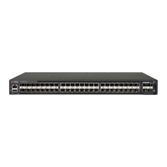
Views of the Brocade ICX 7450 switch Views of the Brocade ICX 7450 switch Figure 1 shows the front view of the Brocade ICX 7450-24 switch. FIGURE 1 Front view of the Brocade ICX 7450-24 System LEDs Mini-USB console port... - Page 15 Views of the Brocade ICX 7450 switch Figure 3 shows the front view of the Brocade ICX 7450-48 switch. FIGURE 3 Front view of the Brocade ICX 7450-48 System LEDs Mini-USB console port Media/Stacking module LEDs Reset button Stack unit ID display...
- Page 16 Views of the Brocade ICX 7450 switch Figure 5 shows the front view of the Brocade ICX 7450-48F switch. FIGURE 5 Front view of the Brocade ICX 7450-48F System LEDs Mini-USB console port Media/Stacking module LEDs Reset button Stack unit ID display...
-
Page 17: Brocade Icx 7450 Slot And Ethernet Port Numbering
Brocade ICX 7450-48 and ICX 7450-48P slot numbering • Slot 1 and Slot 2 are located on the front of the Brocade ICX 7450-48F device. Slot 1 contains 1 GbE SFP ports 1/1/1 through 1/1/48, with odd port numbers on the top row and port 1/1/1 on the left. -
Page 18: Supported Expansion Modules
Figure • Slot 4 is also located on the rear of the Brocade ICX 7450 switch and with a single-port module installed contains 40 GbE QSFP+ stacking/data port 1/4/1, With a 4-port module installed, Slot 4 contains 1/10 GbE SFP+ ports 1/4/1 and 1/4/3 on the top row (left to right), and ports 1/4/2 and 1/4/4 on the bottom row (left to right). -
Page 19: Supported Transceivers And Cables
Supported transceivers and cables TABLE 3 Brocade ICX 7450-48, 48P and 48F expansion slots and supported media modules Module Slot 2 Slot 3 Slot 4 4X1G 4X100M 4X1G 4X100M 4X1G 4X100M ICX7400-4X1GF 4X10G 4X1G 4X10G 4X1G 4X10G 4X1G ICX7400-4X10GF 4X10G... - Page 20 Supported transceivers and cables Brocade ICX 7450 Hardware Installation Guide 53-1003623-02...
-
Page 21: In This Chapter
16“. Unpacking the device The Brocade ICX 7450 ships with all of the items listed in the following list. Verify the contents of your shipping container. If any items are missing, contact the place of purchase. The following items are included in your shipping carton: •... -
Page 22: Installation And Safety Considerations
• Because the Brocade ICX 7450 can be ordered with fans that move air either front to back or back to front, be sure to orient your switch with the airflow pattern of any other devices in the rack. -
Page 23: Location Considerations
“Environmental considerations” page 12. • The Brocade ICX 7450 should be installed with its top and bottom covers parallel to the floor. The Brocade ICX 7450 should not be installed upside down. • Allow a minimum of 3 in. of space between the front and the back of the device and walls or other obstructions for proper airflow. -
Page 24: Installation Tasks
Ensure that the physical environment that will host the device “Installation and safety has the proper cabling and ventilation. considerations” on page 12 If customizing a Brocade ICX 7450 baseline chassis: “Installing and replacing a power supply unit” on page 26 Install at least one power supply unit. -
Page 25: Installation Precautions
Make sure the airflow around the front and sides of the device is not restricted. CAUTION Never leave tools inside the device. CAUTION Risk of explosion if battery is replaced by an incorrect type. Dispose of used batteries according to the manufacturer’s instructions. Brocade ICX 7450 Hardware Installation Guide 53-1003623-02... -
Page 26: Lifting Precautions
The mark is your assurance that the power cord can be used safely with the device. Brocade ICX 7450 Hardware Installation Guide 53-1003623-02... -
Page 27: Installing The Device On A Desktop
Installing the device on a desktop Installing the device on a desktop Complete the following steps to install the ICX 7450 device on a desktop or other flat surface. FIGURE 12 Attaching the adhesive feet 1. Attach the four adhesive feet to the bottom of the device. -
Page 28: 2-Post Rack Mount Installation
Installing the device in a rack or cabinet 2-post rack mount installation The Brocade ICX 7450 can be installed in a 2-post rack in various mounting positions, as shown in Figure FIGURE 13 2-post rack mounting positions Front flush mount... - Page 29 Installing the device in a rack or cabinet FIGURE 14 Attaching the mounting brackets for a Brocade ICX 7450 3. Position the device in the cabinet, providing temporary support under the switch until the rail kit is secured to the cabinet.
-
Page 30: 4-Post Rack Mount Installation
Kits for 4-post rack mounting are not included in the shipping carton and must be ordered separately. NOTE Use the following procedure when installing the Brocade ICX 7450 in a 4-post rack cabinet. For 2-post cabinets, follow the procedures in “2-post rack mount installation”... -
Page 31: Connecting Devices In A Stack
30. Connecting devices in a stack The Brocade ICX 7450 can operate as a standalone device or as a member of a stack. A stack is a group of devices—Brocade stackable units and their connected stacking links—that are connected so that the stack is managed as a single entity. -
Page 32: Stacking Configuration Requirements
Stacking cables Use QSFP+ direct attached copper stacking cables or QSFP+ optics with fiber cables to connect ICX 7450 devices in a stack. The copper cable lengths for 40 GbE ports are 0.5 meter, 1 meter, 3 meters, or 5 meters. - Page 33 Connecting devices in a stack The following figure shows supported stacking topologies, including linear and ring stacking on the rear panel: FIGURE 19 Linear and ring stacking topologies (rear panel) Brocade ICX 7450 Hardware Installation Guide 53-1003623-02...
-
Page 34: Grounding The System
Linear and ring stacking topology (front panel) Grounding the system The rear panel of the Brocade ICX 7450 includes a single-screw grounding terminal. The surface area around this terminal is not painted to provide a good electrical connection. Before connecting power to the device, the grounding terminal must be connected to ground to ensure proper operation and to meet electromagnetic interference (EMI) and safety requirements. -
Page 35: Powering On The System
Use the grounding lug and screw included in the Brocade ICX 7450 grounding kit. Perform the following steps to connect to the grounding terminal. 1. Ensure that the rack in which the Brocade ICX 7450 is mounted is properly grounded and in compliance with local regulations. -
Page 36: Power Supply Usage
Power supplies Power supply usage The Brocade ICX 7450-24P and Brocade ICX 7450-48P models support specific AC or DC power supply inputs and numbers of POE, POE+, High PoE and PoH ports with the internal power supply. TABLE 5 AC power supply and PoE usage... -
Page 37: Installing An Ac Power Supply
CAUTION For Brocade ICX 7450 devices, be sure that the airflow direction of the power supply unit matches that of installed fan trays. The power supplies and fan trays are clearly labeled with either a green arrow with an “E”, or an orange arrow with an “I.”... -
Page 38: Installing A Dc Power Supply
When the Brocade ICX 7450 is powered on, the LEDs on the power supply back panel should light up green to confirm that the power supply is correctly installed and supplying power. - Page 39 When the Brocade ICX 7450 is powered on, the power LED on the front of the device should turn green to confirm that the power supply is correctly installed and supplying power. Refer “Brocade...
-
Page 40: Dc-Dc Power Source Cautions
Baud: 9600 bps • Data bits: 8 • Parity: None • Stop bits: 1 • Flow control: None The console serial communication port serves as a connection point for management by a PC. Brocade ICX 7450 Hardware Installation Guide 53-1003623-02... -
Page 41: Connecting To The Management Port
After you assign an IP address, you can access the Brocade ICX 7450 from anywhere in the attached network using Telnet, a web browser, or other network management tools, such as Brocade Network Advisor. To prevent unauthorized access, Brocade recommends that the management port only be connected to a secure private network. -
Page 42: Connecting Network Devices
Connecting a network device to a fiber port For direct attachment from the device to a Gbps NIC, switch, or router, using a fiber optic transceiver, you will need fiber cabling with an LC connector. Brocade ICX 7450 Hardware Installation Guide 53-1003623-02... -
Page 43: Cleaning The Fiber Optic Connectors
“LED activity interpretation” on page 35. NOTE To verify that a Brocade ICX 7450 can reach another device through the network, use the ping command at any level of the CLI. For more information, refer to the FastIron Ethernet Switch Administration Guide. - Page 44 Connecting network devices Brocade ICX 7450 Hardware Installation Guide 53-1003623-02...
-
Page 45: Brocade Icx 7450 Operation
• Brocade ICX 7450 rear panel LEDs ....... . 41 •... - Page 46 Brocade ICX 7450 front panel LEDs Figure 26 shows the LEDs on the Brocade ICX 7450-24 front panel. The up-arrow port status LEDs for the 1 GbE ports correspond to the upper, odd-numbered ports; the down-arrow port status LEDs correspond to the lower, even-numbered ports.
- Page 47 FIGURE 27 Brocade ICX 7450-24P front panel LEDs The LED definitions for the Brocade ICX 7450-24P are identical to those shown for Brocade ICX 7450-24 (in the table beneath Figure 26 on page 36) except for the PoE+ port LEDs. The PoE+ indicator is on if a port is providing power to the connected device, and off if it is not supplying power.
- Page 48 FIGURE 28 Brocade ICX 7450-48 front panel LEDs The LED definitions for the Brocade ICX 7450-48 are identical to those shown for Brocade ICX 7450-24 (see the table beneath Figure 26 on page 36).
- Page 49 FIGURE 29 Brocade ICX 7450-48P front panel LEDs The LED definitions for the Brocade ICX 7450-48P are identical to those shown for Brocade ICX 7450-24 (in the table beneath Figure 26 on page 36) except for the PoE+ port LEDs. The PoE+ indicator is on if a port is providing power to the connected device, and off if it is not supplying power.
- Page 50 LEDs correspond to the lower, even-numbered ports. FIGURE 30 Brocade ICX 7450-48F front panel LEDs The LED definitions for the Brocade ICX 7450-48F are identical to those shown for Brocade ICX 7450-24 (see the table beneath Figure 26 on page 36).
-
Page 51: Brocade Icx 7450 Rear Panel Leds
Brocade ICX 7450 rear panel LEDs Brocade ICX 7450 rear panel LEDs The Brocade ICX 7450 has the following LEDs on the rear panel: • QSFP+ module LEDs: Four status LEDs (green) for the QSFP+ port. Only the first LED is currently used, and indicates the status of the port in 40 GbE mode. - Page 52 Steady green Steady green means module is operating No action required. normally. For stacking modules, this means that stacking mode is enabled and the switch is the stack master. Brocade ICX 7450 Hardware Installation Guide 53-1003623-02...
- Page 53 No action required. transmitted or received. Steady amber Link is up in 1 GbE mode. No action required. Blinking amber There is 1 GbE traffic and packets are being No action required. transmitted or received. Brocade ICX 7450 Hardware Installation Guide 53-1003623-02...
-
Page 54: Diagnostic Tests And Monitoring
The CLI commands for system diagnostic tests are dm diag and dm alt-diag. These diagnostic tests verify all available hardware components including: • I2C devices • EEPROMS Brocade ICX 7450 Hardware Installation Guide 53-1003623-02... - Page 55 System diagnostic testing runs at link speeds of 10 Gbps or 40 Gbps (for MOD2 QSFP+ data uplink ports) or 40 Gbps (for MOD3/MOD4 QSFP+ stacking ports) depending on the speed of the link being tested and the type of port. Brocade ICX 7450 Hardware Installation Guide 53-1003623-02...
- Page 56 Diagnostic tests and monitoring Brocade ICX 7450 Hardware Installation Guide 53-1003623-02...
-
Page 57: Managing The Brocade Icx 7450
CAUTION The procedures in this chapter are for qualified service personnel. CAUTION Do not unscrew and remove the top cover of the Brocade ICX 7450. There are no user-serviceable parts inside the Brocade ICX 7450. Hardware maintenance schedule Brocade ICX 7450 switch hardware components require minimal maintenance. Brocade recommends cleaning the fiber-optic connectors on a fiber-optic port and the connected fiber cable each time you disconnect the cable. -
Page 58: Removing A Copper Or Fiber-Optic Module
Replacing a copper or fiber-optic module Removing a copper or fiber-optic module You can remove an SFP, SFP+, or QSFP+ transceiver from a slot while the Brocade ICX 7450 is powered on and running. While removing a copper or fiber-optic module, be sure to wear an ESD wrist strap that is connected to ground. -
Page 59: Cleaning The Fiber-Optic Connectors
FRU removal and replacement procedures The field-replaceable units (FRUs) in the Brocade ICX 7450 can be removed and replaced by using a #1 Phillips screwdriver. The switches can continue operating during the FRU replacement if the conditions specified in these procedures are followed. This covers both the power supply unit (PSU) FRUs and fan FRUs. -
Page 60: Replacing A Power Supply Unit
CAUTION For the Brocade ICX 7450 devices, be sure that the airflow direction of the power supply unit matches that of the installed fan tray. The power supplies and fan trays are clearly labeled with either a green arrow with an “E,”... -
Page 61: Determining The Need To Replace A Power Supply
Complete the following steps to replace a power supply in a Brocade ICX 7450. 1. To leave the Brocade ICX 7450 in service while replacing a power supply, verify that the other power supply (the one not being replaced) has been powered on for at least four seconds and has a steady green status LED. -
Page 62: Replacing Fan Trays
Replacing fan trays CAUTION For the Brocade ICX 7450 devices, be sure that the airflow direction of the fan tray matches that of the installed power supply unit. The power supplies and fan trays are clearly labeled with either a green arrow with an “E,” or an orange arrow with an “I.”... -
Page 63: Installing Or Replacing The Fan Assembly
Replacing an expansion module Installing or replacing the fan assembly Complete the following steps to install or replace a fan assembly in a Brocade ICX 7450. 1. If replacing a fan assembly: a. Using a Phillips screwdriver, unscrew the captive screw on the fan assembly. -
Page 64: Time And Items Required
There are no user-serviceable parts inside the expansion module assembly. Time and items required Replacing an expansion module in the Brocade ICX 7450 should take less than two minutes to complete. You need the following items to replace an expansion module in the Brocade ICX 7450: •... - Page 65 8. Push the release latch lever on the module into its closed position. 9. Power on the switch. 10. Verify correct installation by running the show chassis command. CAUTION Empty expansion module slots must be covered using filler panels. Brocade ICX 7450 Hardware Installation Guide 53-1003623-02...
- Page 66 Replacing an expansion module Brocade ICX 7450 Hardware Installation Guide 53-1003623-02...
-
Page 67: Brocade Icx 7450 Specifications
Regulatory compliance (environmental) ......65 This document highlights the features and specifications for the Brocade ICX 7450 Switch.. -
Page 68: Ethernet
System architecture Non-blocking shared-memory switch ICX 7450-24: 24 1-GbE RJ-45 ports, four 10-GbE SFP+ uplink ports, two 40-GbE QSFP+ stacking ports, one power supply, and one fan unit ICX 7450-24P: 24 1-GbE RJ-45 ports (supporting PoE, PoE+, High PoE, PoH), four... -
Page 69: Leds
With one power supply, one fan assembly, two stacking modules, and one 10-GbE media module. System component Description Serial Cable 1 (Mini-USB to RJ-45) RJ-45 to DB9 adaptor AC power cord, power clip For ICX 7450-24, 24P, 48, 48P and 48F units Weight and physical dimensions Model Height Width Depth Weight (with... -
Page 70: Environmental Requirements
47 dBA ICX 7450-48P: 49 dBA ICX 7450-48F: 46 dBA MTBF @ 25°C ICX 7450-24: 399,973 Hours ICX 7450-24P: 317,719 Hours ICX 7450-48: 376,635 Hours ICX 7450-48P: 297,862 Hours ICX 7450-48F: 330,154 Hours Brocade ICX 7450 Hardware Installation Guide 53-1003623-02... -
Page 71: Power Supply Specifications (Per Psu)
139.6 W 129.2W 1 x 250 W AC 1 PSU. 420 BTU/hr 477 BTU/hr 441 BTU/hr 152.8 W 151.6 W 132.78W 1 x 250 W AC 2 PSUs 522 BTU/hr 518 BTU/hr 474 BTU/hr Brocade ICX 7450 Hardware Installation Guide 53-1003623-02... -
Page 72: Power Consumption (Maximum Configuration)
ICX7400-4X10GC Hot-swappable 4-port 1/10GbE copper expansion Typical = 18.72 W module Maximum = 20.76 W ICX7400-1X40GQ Hot-swappable 1-port 40G QSFP+ data uplink / Typical = 5.64 W stacking module Maximum = 7.38 W Brocade ICX 7450 Hardware Installation Guide 53-1003623-02... -
Page 73: Data Port Specifications (Ethernet)
SFP ports, compatible with 100Base-FX IR or LR SFP optic for SMF, 100Base-FX SFP optic MMF, 1000Base-BXD SFP optic SMF, 1000Base-BXU SFP optic SMF, 1000Base-LHA SFP optic SMF, 1000Base-LX SFP optic SMF, 1000Base-SX SFP optic MMF, 1000BASE-TX SFP Copper Brocade ICX 7450 Hardware Installation Guide 53-1003623-02... -
Page 74: Serial Port Specifications (Pinout - Mini-Usb)
Serial port specifications (protocol) Parameter Value Baud 9600 Data bits Parity None Stop bits Flow control None Memory specifications Memory Type Size Main memory DDR3 2 GB Boot Flash NOR Flash 8 MB Brocade ICX 7450 Hardware Installation Guide 53-1003623-02... -
Page 75: Regulatory Compliance (Emc)
U.S. Conflict Minerals. • 30/2011/TT-BCT – Vietnam circular. • SJ/T 11363-2006 Requirements for Concentration Limits for Certain Hazardous Substances in EIPs (China). • SJ/T 11364-2006 Marking for the Control of Pollution Caused by EIPs (China). Brocade ICX 7450 Hardware Installation Guide 53-1003623-02... - Page 76 Regulatory compliance (environmental) Brocade ICX 7450 Hardware Installation Guide 53-1003623-02...
-
Page 77: Brocade Icx 7450 Regulatory Statements
Industry Canada statement Cet appareil numérique de la classe A est conforme à la norme NMB-003 du Canada. English Translation of above statement This Class A digital apparatus complies with Canadian ICES-003. Brocade ICX 7450 Hardware Installation Guide 53-1003623-02... -
Page 78: Europe And Australia (Cispr 22 Class A Warning)
Class A device (Broadcasting Communication Device for Office Use): This device obtained EMC registration for office use (Class A), and may be used in places other than home. Sellers and/or users need to take note of this. Brocade ICX 7450 Hardware Installation Guide 53-1003623-02... -
Page 79: China
English translation of above statement This is a Class A product. In a domestic environment this product may cause radio interference, in which case the user may be required to take adequate measures. Brocade ICX 7450 Hardware Installation Guide 53-1003623-02... -
Page 80: Bsmi Statement (Taiwan)
English translation of above statement Warning: This is a class A product. In a domestic environment this product may cause radio interference in which case the user may be required to take adequate measures. Brocade ICX 7450 Hardware Installation Guide 53-1003623-02... -
Page 81: Appendix C Brocade Icx 7450 Cautions And Danger Notices
CAUTION All devices with DC power supplies (Brocade ICX 7450) are intended for installation in restricted access areas only. A restricted access area is where access can be gained only by service personnel through the use of a special tool, lock and key, or other means of security, and is controlled by the authority responsible for the location. - Page 82 Compare esta suma con el límite nominal para el circuito. Las capacidades nominales de corriente máximas están generalmente impresas en los instrumentos, cerca de los conectores de corriente de entrada. Brocade ICX 7450 Hardware Installation Guide 53-1003623-02...
- Page 83 Si se realizan cambios o modificaciones en este dispositivo sin la autorización expresa de la parte responsable del cumplimiento de las normas, la licencia del usuario para operar este equipo puede quedar anulada. Brocade ICX 7450 Hardware Installation Guide 53-1003623-02...
- Page 84 Pfeil mit dem Buchstaben “I” gekennzeichnet. MISE EN GARDE Pour les équipements de type ICX 7450, veillez à ce que le sens de circulation de l'air du bloc d'alimentation corresponde à celui du tiroir de ventilation installé. Les blocs d'alimentation et les tiroirs de ventilation sont étiquetés d'une flèche verte avec un " E "...
- Page 85 CAUTION For the DC input circuit to the system of a Brocade ICX 7450 make sure there is a 20 Amp circuit breaker, minimum 60 VDC, double pole, on the input lugs to the power supply. The input wiring for connection to the product should be Listed copper wire, 12 AWG, marked VW-1, and rated minimum 90°C.
-
Page 86: Danger Notices
“Gefahr” weist auf eine mögliche Gefährdung hin, die zu Verletzungen oder Tod führen können. Sie finden die folgenden Warnhinweise in diesem Handbuch. Un danger attire votre attention sur un risque possible de blessure ou de décès. Ci-dessous, vous trouverez les avertissements utilisés dans ce manuel. Brocade ICX 7450 Hardware Installation Guide 53-1003623-02... - Page 87 Débranchez le cordon d'alimentation de toutes les sources d'alimentation pour couper complètement l'alimentation du dispositif. PELIGRO Para desconectar completamente la corriente del instrumento, desconecte el cordón de corriente de todas las fuentes de corriente. Brocade ICX 7450 Hardware Installation Guide 53-1003623-02...
- Page 88 Laser Radiation. Do Not View Directly with Optical Instruments. Class 1M Laser Products. GEFAHR Verwenden Sie nur optische Transceiver, die von Brocade Communications Systems zugelassen sind und die die Anforderungen gemas FDA Class 1 Radiation Performance Standards in 21 CFR, Unterkapitel I, und IEC 825-2 erfullen. Optische Produkte, die diese Normen nicht erfullen, konnen Strahlen aussenden, die fur das menschliche Auge gefahrlich sind.
- Page 89 PELIGRO Utilice solo transceptores opticos aprobados por Brocade Communications Systems, Inc. y que cumplan con la norma IEC 825-2 y con los estandares de rendimiento Clase 1 de FDA definidos en el subcapitulo I de 21 CFR. Los productos opticos que no cumplan con estos estandares pueden emitir luz danina para los ojos.
- Page 90 Danger Notices Brocade ICX 7450 Hardware Installation Guide 53-1003623-02...
- Page 91 ESD wrist strap, using cable management, recommendations Ethernet port numbering cables, supported expansion module circuit overloading description cleaning fiber-optic modules replacement Brocade ICX 7450 Hardware Installation Guide 53-1003623-02...
- Page 92 10GbE SFP+ 1GbE SFP QSFP+ indicators, LED mounting brackets installation MS LED 2-post rack MyBrocade website 4-post rack cabinet desktop location SFP+ transceivers numbering, slots and ports tasks interference, electrical IP address, assignment Brocade ICX 7450 Hardware Installation Guide 53-1003623-02...
- Page 93 2-post 4-post rear panel view universal rack mount kit redundancy, power supplies and fans USB port Reset button, location RJ-45 ports,location wiring assembly, DC power Brocade ICX 7450 Hardware Installation Guide 53-1003623-02...
- Page 94 Brocade ICX 7450 Hardware Installation Guide 53-1003623-02...
Need help?
Do you have a question about the ICX 7450 and is the answer not in the manual?
Questions and answers