Brocade Communications Systems Brocade ICX 6450-C Hardware Installation Manual
Compact switch
Hide thumbs
Also See for Brocade ICX 6450-C:
- Hardware installation manual (63 pages) ,
- Software update (128 pages)

Related Manuals for Brocade Communications Systems Brocade ICX 6450-C


Summary of Contents for Brocade Communications Systems Brocade ICX 6450-C
- Page 1 53-100281X-01 ® 24 August 2013 Brocade ICX 6450-C Compact Switch Hardware Installation Guide Supporting software release 08.0.00a on device models ICX 6450-C12-PD...
- Page 2 Export of technical data contained in this document may require an export license from the United States government. The authors and Brocade Communications Systems, Inc. shall have no liability or responsibility to any person or entity with respect to any loss, cost, liability, or damages arising from the information contained in this book or the computer programs that accompany it.
-
Page 3: Table Of Contents
Power precautions ........13 Brocade ICX 6450-C Compact Switch Hardware Installation Guide... - Page 4 China ..........45 Brocade ICX 6450-C Compact Switch Hardware Installation Guide...
- Page 5 Danger notices ......... . 52 Brocade ICX 6450-C Compact Switch Hardware Installation Guide...
- Page 6 Brocade ICX 6450-C Compact Switch Hardware Installation Guide 53-1002817-02...
-
Page 7: About This Guide
If you are using a Brocade Layer 3 Switch, you should be familiar with the following protocols if applicable to your network – IP, RIP, OSPF, BGP, ISIS, IGMP, PIM, DVMRP, and VRRP. Brocade ICX 6450-C Compact Switch Hardware Installation Guide 53-1002817-02... -
Page 8: Document Conventions
The following notices and statements are used in this manual. They are listed below in order of increasing severity of potential hazards. NOTE A note provides a tip, guidance or advice, emphasizes important information, or provides a reference to related information. Brocade ICX 6450-C Compact Switch Hardware Installation Guide 53-1002817-02... -
Page 9: Related Publications
FastIron Ethernet Switch Stacking Configuration Guide • FastIron Ethernet Switch Traffic Management Guide • Unified IP MIB Reference Getting technical help To contact Technical Support, go to http://www.brocade.com/services-support/index.page for the latest e-mail and telephone contact information. Brocade ICX 6450-C Compact Switch Hardware Installation Guide 53-1002817-02... -
Page 10: Document Feedback
Provide the title and version number of the document and as much detail as possible about your comment, including the topic heading and page number and your suggestions for improvement. Brocade ICX 6450-C Compact Switch Hardware Installation Guide 53-1002817-02... -
Page 11: Product Overview
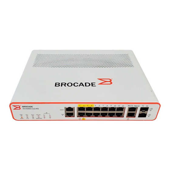
Powered Device (PD) capable and 2 x 1G SFP uplink ports. The uplink and stacking ports are also MACsec-capable. Figure 1 Figure 2 show the front and rear panels of the ICX 6450-C models. FIGURE 1 ICX 6450-C12-PD front panel Brocade ICX 6450-C Compact Switch Hardware Installation Guide 53-1002817-02... -
Page 12: Network And Management Interfaces
PC. Out-of-band management interface The out-of-band management interface is an RJ45 port that allows you to configure and manage the device from the network. Brocade ICX 6450-C Compact Switch Hardware Installation Guide 53-1002817-02... -
Page 13: Reset Button
The 10/100/1000 BASE-T RJ45 PD1/C1 and PD2/C2 ports, residing on slot 2 of the device, can be used as uplink ports or additional network connections. They can also be used as PD ports. Brocade ICX 6450-C Compact Switch Hardware Installation Guide 53-1002817-02... -
Page 14: Port, System, And Power Status Leds
Port status LEDs Figure 5 shows the location of the port status LEDs on the ICX 6450-C12-PD model. FIGURE 5 Port status LEDs an ICX 6450-C12-PD device Port status LEDs PoE/PoE+ LEDs Brocade ICX 6450-C Compact Switch Hardware Installation Guide 53-1002817-02... -
Page 15: System Status Leds
System status LEDs Figure 6 shows the location of the system status LEDs on an ICX 6450-C device. FIGURE 6 System status LEDs on an ICX 6450-C12-PD device System status LEDs Brocade ICX 6450-C Compact Switch Hardware Installation Guide 53-1002817-02... - Page 16 LED is reserved for future use. (Reserved for future use) Downlink LED is reserved for future use. (Reserved for future use) ID (1-4) LED is reserved for future use. (Reserved for future use) Brocade ICX 6450-C Compact Switch Hardware Installation Guide 53-1002817-02...
-
Page 17: Network Connection Status Leds
Verify that the connection to the other network device has been properly made. • If the other actions do not resolve the problem, try using a different port or a different cable. Brocade ICX 6450-C Compact Switch Hardware Installation Guide 53-1002817-02... - Page 18 • If the other actions do not resolve the problem, try using a different port or a different cable. If a problem persists after taking these actions, contact Brocade Technical Support. Brocade ICX 6450-C Compact Switch Hardware Installation Guide 53-1002817-02...
-
Page 19: Power Supplies
PD power usage An ICX 6450-C device can be powered using PoE/PoE+ provided by a Power Sourcing Equipment (PSE). Table 6 shows the device power usage in the PD power mode. Brocade ICX 6450-C Compact Switch Hardware Installation Guide 53-1002817-02... - Page 20 None 1 PoE+ and 1 PoE 38.85 29.62 18.67 7 (one Class 2 device) None 2 PoE+ 50.8 39.92 18.67 22.4 • One Class 3 device • One Class 2 device Brocade ICX 6450-C Compact Switch Hardware Installation Guide 53-1002817-02...
-
Page 21: Items Included With An Icx 6450-C Device
A wall mount option is available to order for a secure wall mount, in addition to the basic wall mount. • An additional rack-mounting kit is available to order to mount the device in a two-post rack. Brocade ICX 6450-C Compact Switch Hardware Installation Guide 53-1002817-02... -
Page 22: Summary Of Installation Tasks
40 ο C (104 ο F). CAUTION Make sure the airflow around the front, sides, and back of the device is not restricted. CAUTION Never leave tools inside the device. Brocade ICX 6450-C Compact Switch Hardware Installation Guide 53-1002817-02... -
Page 23: Lifting Precautions
Cabling infrastructure Ensure that the proper cabling is installed at the site. For information about supported SFP and SFP+ transceivers and cable lengths and types, refer to the following Brocade website: Brocade ICX 6450-C Compact Switch Hardware Installation Guide 53-1002817-02... -
Page 24: Installation Location
Mechanical loading: Do not place any equipment on top of a rack-mounted unit. • Circuit overloading: Be sure that the supply circuit to the rack assembly is not overloaded. • Grounding: Rack-mounted equipment should be properly grounded. Brocade ICX 6450-C Compact Switch Hardware Installation Guide 53-1002817-02... -
Page 25: Installing The Device
3. If installing a single device only, refer to “Powering on the system” on page 29. Place each device squarely on top of the one below. 4. If installing multiple devices, attach the adhesive feet to each device. Brocade ICX 6450-C Compact Switch Hardware Installation Guide 53-1002817-02... -
Page 26: Rack Mount Installation
4. Insert the cage nuts in the two-post rack where you want to mount the device. See Figure 5. Using a Phillips screwdriver, mount the device in a two-post rack using four rack-mounting screws, as illustrated in Figure Brocade ICX 6450-C Compact Switch Hardware Installation Guide 53-1002817-02... -
Page 27: Wall Mount Installation
When mounting the device on a wall, Brocade recommends that you mount the device with the port side down. Complete the following steps to mount the device directly to a wall. Brocade ICX 6450-C Compact Switch Hardware Installation Guide 53-1002817-02... - Page 28 4. Use the #2 Phillips screwdriver to secure the two wall mount screws into the wall mount anchors. Leave a gap of 4.0 to 4.5 mm between the screw head and the wall. See Figure Brocade ICX 6450-C Compact Switch Hardware Installation Guide 53-1002817-02...
- Page 29 Installing the device FIGURE 11 Preparing to wall mount the device Drilled holes in wall Wall mount screws Wall mount anchors 4.0- 4.5 mm space between screw head and wall Brocade ICX 6450-C Compact Switch Hardware Installation Guide 53-1002817-02...
- Page 30 See Figure 12 Figure FIGURE 12 Wall mounting the ICX 6450-C device - View of rear panel FIGURE 13 Wall mounting the ICX 6450-C device - View of the top panel Brocade ICX 6450-C Compact Switch Hardware Installation Guide 53-1002817-02...
-
Page 31: Wall Mount Installation Using Wall Mount Brackets
(Brocade Part Number: ICX6400-RMK). The rack-mount kit is not included with the device. Brocade recommends that you wall mount the device with the port side down. Complete the following steps to mount the device to a wall. Brocade ICX 6450-C Compact Switch Hardware Installation Guide 53-1002817-02... - Page 32 3. Hammer two wall mount anchors into the holes on the wall, as illustrated in Figure 4. Use the two wall mount screws to fasten the device to the wall mount anchors, as illustrated in Figure Brocade ICX 6450-C Compact Switch Hardware Installation Guide 53-1002817-02...
-
Page 33: Mounting The Device With A Magnet
Use the magnet mount kit to mount the device on a metal wall or a metal surface, including underneath a metal desk. The magnet mount kit is available for order separately from the device and consists of a single magnet sheet. Brocade ICX 6450-C Compact Switch Hardware Installation Guide 53-1002817-02... - Page 34 The magnet sheet can only be placed against the bottom panel of the device. Do not attempt to attach the magnet sheet to any other panels on the device. FIGURE 16 Attaching the logo side of the magnet sheet to the bottom panel of the ICX 6450-C device Brocade ICX 6450-C Compact Switch Hardware Installation Guide 53-1002817-02...
- Page 35 2. Place the magnet sheet (with the logo side now attached to the bottom panel of the device) against the metal surface or metal wall. See Figure 17 Figure FIGURE 17 Mounting an ICX 6450-C device to a metal surface using the magnet mount Brocade ICX 6450-C Compact Switch Hardware Installation Guide 53-1002817-02...
- Page 36 Installing the device FIGURE 18 An ICX 6450-C device securely mounted on a metal surface with ports facing down Brocade ICX 6450-C Compact Switch Hardware Installation Guide 53-1002817-02...
- Page 37 2. Place the bottom panel of the device with the magnet sheet attached under the metal desk, against the side of the device. Ensure that the front panel (port side) of the device is facing downward. See Figure 19 Figure Brocade ICX 6450-C Compact Switch Hardware Installation Guide 53-1002817-02...
- Page 38 Ensure that adequate ventilation is provided for the system. A 7.62 cm (3-inch) clearance is recommended on each side. FIGURE 19 Mounting an ICX 6450-C device underneath a metal desktop using the magnet mount Magnet Metal desk Brocade ICX 6450-C Compact Switch Hardware Installation Guide 53-1002817-02...
-
Page 39: Powering On The System
2. Attach the AC power cord to the AC connector on the rear panel. 3. Insert the power cord plug into a 100V-240V outlet. NOTE To turn the system off, simply unplug the power cord or cords. Brocade ICX 6450-C Compact Switch Hardware Installation Guide 53-1002817-02... - Page 40 Powering on the system Brocade ICX 6450-C Compact Switch Hardware Installation Guide 53-1002817-02...
-
Page 41: Configuring An Icx 6450-C Device
IP address that has a network mask with 24 significant (“mask”) bits. By default, the CLI displays network masks in classical IP address format (for example, 255.255.255.0). You can change the display to the prefix format. Brocade ICX 6450-C Compact Switch Hardware Installation Guide 53-1002817-02... - Page 42 IP address configuration Brocade ICX 6450-C Compact Switch Hardware Installation Guide 53-1002817-02...
-
Page 43: Managing An Icx 6450-C Device
TABLE 8 Temperature thresholds Model Warning level temperature threshold Critical (shutdown) temperature threshold °C) °C) ICX 6450-C12-PD Brocade recommends setting the 88°C warning level temperature no higher than 83°C. Brocade ICX 6450-C Compact Switch Hardware Installation Guide 53-1002817-02... -
Page 44: Displaying The Temperature
When the temperature crosses the critical (shutdown) threshold levels, the device will reset after 5 minutes. The following console and syslog message is displayed: !!! Temperature is over shutdown level, please shutdown your stack unit 1 to avoid hw damage!!! Brocade ICX 6450-C Compact Switch Hardware Installation Guide 53-1002817-02... - Page 45 Temperature settings NOTE Brocade recommends that you shut down your stack unit to avoid any hardware damage. Brocade ICX 6450-C Compact Switch Hardware Installation Guide 53-1002817-02...
- Page 46 Temperature settings Brocade ICX 6450-C Compact Switch Hardware Installation Guide 53-1002817-02...
-
Page 47: Ac Power Supply Specifications
0.34 Amp 17.66 W 60.08 0.79 Amp 91.18 W 370.93 200VAC 0.25 Amp 17.86 W 60.76 0.50 Amp 92.05 W 374.58 240VAC 0.22 Amp 18.11 W 61.61 0.43 Amp 92.60 W 377.30 Brocade ICX 6450-C Compact Switch Hardware Installation Guide 53-1002817-02... -
Page 48: Physical Dimensions And Weight
Ambient temperature for cold start 0 ºC TABLE 15 ICX 6450-C Storage altitude environment Storage altitude 15,000 ft (4572 m) maximum TABLE 16 ICX 6450-C Operating altitude environment Operating altitude 10,000 ft (3049 m) maximum Brocade ICX 6450-C Compact Switch Hardware Installation Guide 53-1002817-02... -
Page 49: Pinouts And Signalling
For an ICX 6450-C device to operate at 240V, the power cord should be C13 type connector with 10A rating or better. All devices ship with United States compatible power cords at the time of order. United Kingdom- and European-compatible power cords are also available. Brocade ICX 6450-C Compact Switch Hardware Installation Guide 53-1002817-02... - Page 50 Pinouts and signalling Brocade ICX 6450-C Compact Switch Hardware Installation Guide 53-1002817-02...
-
Page 51: Chapter 6 Troubleshooting
Verify that all system components have been properly installed. If one or more components appear to be malfunctioning (such as the power cord or network cabling), test them in an alternate environment where you are sure that all the other components are functioning properly. Brocade ICX 6450-C Compact Switch Hardware Installation Guide 53-1002817-02... - Page 52 Diagnosing switch indicators Brocade ICX 6450-C Compact Switch Hardware Installation Guide 53-1002817-02...
-
Page 53: Regulatory Statements
Machine noise information regulation - 3. GPSGV, the highest sound pressure level value is 70.0 dB(A) in accordance with EN ISO 7779. Maschinenlärminformations-Verordnung - 3. GPSGV, der höchste Schalldruckpegel beträgt 70.0 dB(A) gemäss EN ISO 7779. Brocade ICX 6450-C Compact Switch Hardware Installation Guide 53-1002817-02... -
Page 54: Japan (Vcci)
Class A device (Broadcasting Communication Device for Office Use): This device obtained EMC registration for office use (Class A), and may be used in places other than home. Sellers and/or users need to take note of this. Brocade ICX 6450-C Compact Switch Hardware Installation Guide 53-1002817-02... -
Page 55: China
English translation of above statement This is a Class A product. In a domestic environment this product may cause radio interference, in which case the user may be required to take adequate measures. Brocade ICX 6450-C Compact Switch Hardware Installation Guide 53-1002817-02... -
Page 56: Bsmi Statement (Taiwan)
For the ICX 6400-EPS1500 device only: 電源線安全性: 重要 : 在連接前, 請確定所用為合適的電源線 警告及注意訊息 警告 : 本產品不含任何可自行維修的零件。 警告 : 本裝置的安裝及拆卸作業必須交由合格的專業人員執行。 警告 : 將本裝置連接至電源插座時, 請將三極電源插頭上的磁場接地導線連接至 正常作用的接地線, 避免發生觸電危險。 警告: 本產品輸出含有危險能量, 為避免操作時發生危險, 須於裝入系統機殼並 所有設備安裝妥當後才可開啟電源。 警告: 本產品之電源輸出非屬電力限制型電源, 請連接使用具防火外殼之周邊, 以避免火災危險發生。 注意 : 請戴上防靜電手環或採取適當的措施, 避免操作本設備時產生靜電放電。 Brocade ICX 6450-C Compact Switch Hardware Installation Guide 53-1002817-02... -
Page 57: Regulatory Compliance
Immunity: • EN 61000-6-1, Electromagnetic Compatibility, Generic Standard • EN 55024, Information Technology equipment - Immunity Characteristics Safety: • BI-NAT CSA 60950-1-07/UL 60950-1 Second Edition • EN 60950-1:2006 • IEC 60950-1:2005 Brocade ICX 6450-C Compact Switch Hardware Installation Guide 53-1002817-02... - Page 58 Regulatory compliance Brocade ICX 6450-C Compact Switch Hardware Installation Guide 53-1002817-02...
-
Page 59: Cautions And Danger Notices
PRECAUCIÓN Use un circuito derivado separado para cada cordón de alimentación de CA, con lo que se proporcionará redundancia en caso de que uno de los circuitos falle. Brocade ICX 6450-C Compact Switch Hardware Installation Guide 53-1002817-02... - Page 60 Si usted borra accidentalmente la configuración en un sistema ya configurado, introduzca el comando write memory (escribir memoria) para guardar la configuración en ejecución en el archivo startup-config. Brocade ICX 6450-C Compact Switch Hardware Installation Guide 53-1002817-02...
- Page 61 Freiraum, auf beiden Seiten jeweils 8 cm Freiraum empfohlen. PRECAUCIÓN Asegúrese de proporcionar una ventilación adecuada al sistema. Se recomienda dejar 3 cm de espacio libre por encima del dispositivo y 8 cm a cada lado. Brocade ICX 6450-C Compact Switch Hardware Installation Guide 53-1002817-02...
-
Page 62: Danger Notices
"Gefahr" weist auf eine mögliche Gefährdung hin, die zu Verletzungen oder Tod führen können. Sie finden die folgenden Warnhinweise in diesem Handbuch. Un danger attire votre attention sur un risque possible de blessure ou de décès. Ci-dessous, vous trouverez les avertissements utilisés dans ce manuel. Brocade ICX 6450-C Compact Switch Hardware Installation Guide 53-1002817-02... - Page 63 Monte los instrumentos que instale en un bastidor o armario lo más bajos posible. Ponga el instrumento más pesado en la parte inferior y los instrumentos progresivamente más livianos más arriba. Brocade ICX 6450-C Compact Switch Hardware Installation Guide 53-1002817-02...
- Page 64 Pour des raisons de sécurité, la dragonne ESD doit contenir une résistance de série 1 méga ohm. PELIGRO Por razones de seguridad, la correa de muñeca ESD deberá contener un resistor en serie de 1 mega ohmio. Brocade ICX 6450-C Compact Switch Hardware Installation Guide 53-1002817-02...
Need help?
Do you have a question about the Brocade ICX 6450-C and is the answer not in the manual?
Questions and answers