Table of Contents
Advertisement
Advertisement
Table of Contents

Related Manuals for Stratasys J750


Summary of Contents for Stratasys J750
- Page 1 User Guide J750 3D Printing System DOC-08010 Rev. E1...
- Page 2 This documentation contains proprietary information of Stratasys Ltd. This information is supplied solely to assist authorized users of J750 3D printing systems. No part of this document may be used for other purposes, and it may not be disclosed to other parties.
- Page 3 This product is covered by one or more of the following U.S. patents: 5,386,500 6,259,962 6,569,373 6,658,314 6,850,334 7,183,335 7,209,797 7,225,045 7,364,686 7,369,915 7,479,510 7,500,846 7,604,768 7,628,857 7,658,976 7,725,209 Stratasys Ltd. http://www.stratasys.com DOC-08010 Revision E1 June 2016 DOC-08010 Rev. E...
-
Page 4: Table Of Contents
For More Information Terms Used in This Guide 2 Safety Safety Features Symbols and Warning Labels Safety Guidelines Printer Installation Printer Operation UV Radiation Printer Maintenance Model and Support Materials UV Lamps First Aid for Working with Printing Materials Contact with Skin Contact with Eyes Ingestion Inhalation Waste Disposal 3 Introducing the J750 3D Printing System Work Configurations Source Files VRML Files Workflows Printing Materials Storage Shelf Life Exposure to Light Safety Considerations Disposal Work Environment Workstation Requirements Preparing Files for Use with PolyJet 3D Printing Systems Converting CAD Files to STL Format Converting CAD Files to WRL Format PolyJet Studio Software 3-10 4 Installing PolyJet Studio How to Install PolyJet Studio... - Page 5 5-33 Zooming 5-34 Handling Trays 5-35 Tray Validation 5-35 Production Estimates 5-36 Printing the Tray 5-37 Printing-Modes 5-38 Saving Trays 5-39 Opening a New Build Tray 5-41 Monitoring and Managing Print Jobs 5-43 Manager Screen 5-43 Setting the Printer Connection 5-46 Job Commands 5-47 Printing Jobs from the Printing Queue 5-47 Resuming Jobs 5-47 Restarting Jobs 5-48 6 Operating and Maintaining the J750 3D Printer Starting the P rinter Loading Model and Support Cartridges DOC-08010 Rev. E...
- Page 6 Producing Models Preparing the Printer Printer Interface Color Key Printing Indicators Resuming Production After Printing has Stopped 6-10 Changing the Printing Material 6-12 Changing Model Materials Without Flushing 6-17 Advanced Settings 6-19 Keeping the Printer in Idle Mode 6-22 Shutting Down the Printer 6-23 Shutdown Wizard 6-24 Maintaining the Printer 6-27 Routine Maintenance Schedule 6-27 Maintenance Counters 6-28 UV Lamp Check 6-30 Pattern Test 6-30 Improving Print Quality 6-32 Cleaning the Print Heads, Roller and Wiper 6-32 Cleaning the Roller Waste Collector and Inspecting the Roller Scraper 6-36 Replacing the Roller Scraper 6-39 Aligning the Print Heads 6-41 Optimizing (Calibrating) Print Heads 6-45 Replacing Print Heads 6-52 Testing and Calibrating the UV Lamps...
-
Page 7: Using This Guide
About This Guide Using This Guide For More Information Terms Used in This Guide DOC-08010 Rev. E... -
Page 8: For More Information
Stratasys J750 User Guide 1 About This Guide Using This Guide This user guide provides instructions for installing, operating and maintaining J750 3D printing systems. It explains how to use features, and provides practical examples to guide you as you use the system. The text and figures in this guide are based on the J750 3D printer, printer software version 85.01.0 and PolyJet Studio software version 10.8.10. This guide assumes that— • all the hardware, software, and network components of your J750 system are installed, configured, and operating correctly. ® • the operator has a working knowledge of the Windows PC platform. For More Information Visit http://www.stratasys.com/ to download additional documents for this printer, including documents in other languages. Also available on this site: details about consumables and support contacts. If you have any questions or comments about the way information is presented in this document, or if you have any suggestions for future editions, please send a message to c-support@stratasys.com. DOC-08010 Rev. E... -
Page 9: Terms Used In This Guide
Stratasys J750 User Guide 1 About This Guide Terms Used in This Guide In PolyJet Studio software: The surface displayed on the Build tray screen that represents the actual build tray in the printer. In the printer: The surface upon which models are produced. Cleaning fluid Cleanser for flushing material feed tubes and the printing block, used to completely remove Model and Support material from the system before loading another type of material in the printer and before long-term shutdown. The cleaning fluid is supplied in standard material cartridges. Client/user workstation The workstation on which s oftware is installed for preparing build trays for production on PolyJet printers. (There is no limit to the number of client workstations in the local network.) Connex™ The technology of printing models by jetting multiple materials simultaneously from the print heads. This technology enables ... - Page 10 Stratasys J750 User Guide 1 About This Guide Resin The base substance from which photopolymer printing materials are made for use in Stratasys PolyJet printers. In PolyJet Studio and printer-application screens, “resin” refers to cartridges of model and support materials. A file type used with PolyJet Studio software. Support material Material used for supporting the structure of models during production. DOC-08010 Rev. E...
-
Page 11: Safety Features
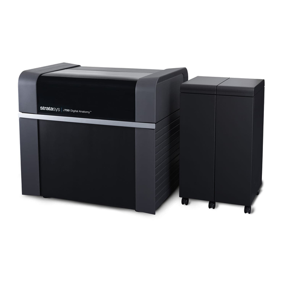
Safety Safety Features Symbols and Warning Labels Safety Guidelines Printer Installation Printer Operation UV Radiation Printer Maintenance Model and Support Materials UV Lamps First Aid for Working with Printing Materials Contact with Skin Contact with Eyes Ingestion Inhalation Waste Disposal DOC-08010 Rev. E... - Page 12 If the safety lock does not function correctly, do not use the printer, and contact your service provider. The transparent section of the cover blocks harmful UV UV Screening radiation, allowing the operator to view the model as it is being made. Figure 2-1 Front view of the J750 printer The power to the printer is turned off in case of electrical Circuit Breaker overcurrent. Note: The circuit breaker is only accessible to service personnel. DOC-08010 Rev. E...
- Page 13 Grounded Chassis The chassis of the printer is grounded, to prevent electrical shock. Note: The power outlet must be properly grounded, in accordance with the local electric code, to provide this protection. If the J750 3D printing system is not used as specified in this guide, the safety features may not provide adequate protection. Symbols and Warning Labels This following table lists the warning labels located on or in J750 printers. Warning Symbol Meaning Location Comments...
- Page 14 Stratasys J750 User Guide 2 Safety Safety Guidelines The following general guidelines, together with the instructions provided throughout this user guide, ensure user safety while operating and maintaining the system. If the system is not operated as specified, the user's safety may be compromised. Printer ➢ Installation and removal of the printer should only be done by qualified Installation service personnel. ➢ Connect the printer (and the UPS unit) to the electric outlet using a power cord that is safety-certified. ➢ The electric outlet should be easily accessible, near the printer. ➢ Never connect the power plug to an outlet that does not have a ground (earth) wire, and never disconnect the ground. Doing so might expose the operator to serious danger from electric shock. ➢ The following safety statement is followed by translations to Finish, ...
- Page 15 Stratasys J750 User Guide 2 Safety UV Radiation The UV lamps used in the printer emit dangerous radiation. ➢ If the UV lamps remain on when the printer is open, do not stare directly at the UV light. Shut down the printer and call your Stratasys service provider. Printer ➢ Service operations should be performed only by qualified personnel who Maintenance have been instructed in relevant safety precautions. ➢ Notify co-workers and those who have access to the J750 system before beginning non-routine and hazardous work. Report any potential dangers and safety-related accidents to your safety officer or to other appropriate authorities. Model and Support materials are made of chemical substances. Although Model and precautions must be taken when handling these materials directly, all Model ...
- Page 16 Stratasys J750 User Guide 2 Safety UV Lamps UV lamps used by the printer to cure printing materials contain a small amount of mercury. In the unlikely event of lamp breakage, avoid inhaling mercury vapor, and ventilate the room. If the lamp ruptures (breaks) during operation, leave the room and ventilate it thoroughly for about 30 minutes. Use protective gloves to prevent contact with mercury and other lamp components. Carefully remove spilled mercury with a method that prevents the generation of mercury vapor, such as a syringe, packing tape or paper. Place the broken lamp, mercury and contaminated materials in an air-tight, non-metallic container. Dispose of the container in accordance with applicable regulations. DOC-08010 Rev. E...
-
Page 17: Ingestion
Stratasys J750 User Guide 2 Safety First Aid for Working with Printing Materials In general, try to avoid direct contact with uncured printing material. If skin or eyes come into contact with it, wash the area immediately and thoroughly with water, and follow these first-aid instructions. The Material Safety Data Sheet (MSDS) that accompanies printing materials contains important safety information. Keep this in an accessible place where these materials are used and stored. -
Page 18: Inhalation
Stratasys J750 User Guide 2 Safety Inhalation Vapors from printing materials can be irritating to the respiratory system. If respiratory irritation occurs, expose the victim to fresh air immediately. ➢ If the victim has stopped breathing, perform artificial respiration or cardiopulmonary resuscitation. ➢ Seek medical attention immediately. ➢ Keep the victim warm but not hot. ➢ Never feed anything to an unconscious person. ➢ Oxygen should be administered by authorized personnel only. Waste Disposal Fully cured printed models can be disposed of as ordinary office trash. However, special care is required when handling printer waste (uncured printing material). ➢ When removing the waste container from the J750 printer, wear Printing Materials neoprene or nitrile gloves. ➢ To prevent liquid waste from splashing into the eyes, wear safety goggles. ➢ Liquid waste from the J750 printer is classified as hazardous industrial waste. Therefore, printing-material waste must be packaged and disposed of in a manner that prevents human contact with it and contamination of water sources. ➢ Empty Model-material and Support-material cartridges contain residue of their contents. Some leakage of this residue may occur through the broken ... - Page 19 Introducing the J750 3D Printing System Work Configurations Source Files VRML Files Workflows Printing Materials Storage Shelf Life Exposure to Light Safety Considerations Disposal Work Environment Workstation Requirements Preparing Files for Use with PolyJet 3D Printing Systems 3-9 Converting CAD Files to STL Format Converting CAD Files to WRL Format PolyJet Studio Software 3-10 DOC-08010 Rev. E...
-
Page 20: 3 Introducing The J750 3D Printing System
Stratasys J750 User Guide 3 Introducing the J750 3D Printing System The advanced capabilities of J750 3D printing systems are made possible by technology specially developed by Stratasys for printing models simultaneously with up to six different Model materials. PolyJet Studio supports these capabilities when preparing trays of models for printing on these systems. • You c an streamline and economize the process of producing models: ❒ Printing models made from different materials on the same build tray (“mixed tray”), in the same print job, eliminates the time-consuming need and expense of loading another material, flushing the system, and sending a separate job to be printed. ❒ Alternating print jobs that use any of the Model materials (or material combinations) loaded similarly does not require material replacement—again, saving time and expense. • You can print objects with combinations of basic materials (digital materials), enabling you to choose from a wide range of possible mechanical properties—from flexible to rigid. • You can print parts (shells) of the same model—simultaneously—with different materials (or material combinations) • You can print objects that have a “coating” made from a different material than the main part of the object. • You can mix any combination of base materials, resulting in an extremely wide range of available colors. • If you designate colors for parts of a model at the design stage (with CAD software) and save the model as a VRML file, the parts are automatically assigned appropriate material combinations in PolyJet Studio for printing ... -
Page 21: Work Configurations
Stratasys J750 User Guide 3 Introducing the J750 3D Printing System Work Configurations The J750 3D printing system can be set up as a single-station system or as a multi-station system. When connected to a local computer network, the system can serve multiple users. In such configurations, each user workstation (client) prepares files f or production. A software service installed on the printer computer acts as a job manager that sends production jobs to the printer for production. Figure 3-2 shows the printer set up in a multi-client configuration. Figure 3-2 Multi-client network configuration When installing PolyJet Studio, you choose whether to install it either as a client station or as a master (server or standalone) station. PolyJet Studio receives jobs in the order they were sent. In multi-workstation configurations, the operator of the server—typically the production administrator—has total control over the jobs sent to the 3D printer, and can prioritize and delete jobs, review job history and reprint a job, and so on. DOC-08010 Rev. E... -
Page 22: Source Files
Stratasys J750 User Guide 3 Introducing the J750 3D Printing System Source Files PolyJet printing systems produce three-dimensional models designed with most CAD tools and some other 3D applications. Supported file formats: • STL • VRML J750 systems feature the capability of producing different types of model files simultaneously. VRML i s a 3D file format which includes color and texture information. VRML Files VRML provides the ability to apply different colors and textures to a model while designing models in a CAD program. No further color assignment is needed in PolyJet Studio. PolyJet Studio supports the VRML 97 and VRML 2.0 formats. When you create a VRML file in CAD software, two files are created: a wrl file, containing the model's geometric information of the model, including texture, and a picture file ( bmp, png, jpg, or tiff), containing the model's color information. Before inserting a VRML file onto the PolyJet Studio build tray, save the VRML file and its corresponding picture file in the same directory. DOC-08010 Rev. E... -
Page 23: Workflows
Stratasys J750 User Guide 3 Introducing the J750 3D Printing System Workflows With PolyJet printing systems, you have great flexibility in preparing model files and printing them. Below are the major workflows available. Detailed instructions for implementing the listed tasks are in Chapter 5 ("Using PolyJet Studio"). Stage Workflow A Workflow B Workflow C CAD program • Design a 3D object. • Design a 3D object. • Design a 3D object. -
Page 24: Printing Materials
Stratasys J750 User Guide 3 Introducing the J750 3D Printing System Printing Materials J750 printers produce models by jetting thin layers of printing materials on the build tray, until the complete model is formed. Two types of material are used in this process: • Model material—which makes up the finished model • Support material—which fills gaps and spaces in the model during printing, and is removed after printing For up-to-date information about PolyJet printing materials and their properties, go to http://www.stratasys.com/materials/polyjet. Materials used for printing models with J750 printers are made of resins, Storage which are composed of reactive monomers and oligomers. Although printing materials are supplied in sealed, UV-proof cartridges, care must be taken when storing and handling them. Follow these guidelines to protect operators and the environment, and to ensure optimum results. • To ensure product stability, do not allow these materials to come into contact with metal. Plastics made from monomer-soluble substances (such ... -
Page 25: Disposal
Stratasys J750 User Guide 3 Introducing the J750 3D Printing System Safety Before being cured, resins are hazardous materials. To prevent possible health Considerations hazards, follow these precautions regarding printing materials: • Do not expose to flames, heat or sparks. • Prevent contact with skin and eyes. • Ventilate areas where they are handled. • Keep them separate from food and drink. Cured plastic parts, however, are safe. They can be handled and stored without precautions. You can find more safety information about resins in: "Safety Guidelines" on page 2-4 "First Aid for Working with Printing Materials" on page 2-7 Dispose of cartridges of model and support material in accordance with all ... -
Page 26: Workstation Requirements
• Intel® Express Chipset—82915G/GV, 82910GL, Q965, Q963, Q35, Q45, Q43, 82852, 82855 • ATI Radeon™ HD 5670, HD 5970 • AMD Radeon™ E6760 Most anti-virus programs can be used with the server workstation. Programs by vendors listed were tested in Stratasys labs. DOC-08010 Rev. E... -
Page 27: Preparing Files For Use With Polyjet 3D Printing Systems
4. In the file format option, choose binary or ASCII. (Both binary and ASCII formats can be used in PolyJet Studio. However, binary files are smaller, so this option is recommended.) 5. Click OK or Save. After converting the model files, it is recommended that you check them for ® defects in an STL-repair application (such as Magics™, by Materialise ) before opening them in PolyJet Studio and producing the model. For more information, search for "CAD to STL" on www.stratasys.com. You can save CAD designs as VRML files (WRL format) for printing. If you Converting assign RGB values to shells (parts) in the CAD design and then import the CAD Files to VRML file in PolyJet Studio, Digital Materials that provide the best color WRL Format match are automatically assigned to the shells. The printer fabricates these Digital Materials from the base materials loaded in the printer. PolyJet Studio supports VRML 2 files (also known as VRML97 files). -
Page 28: Polyjet Studio Software
Stratasys J750 User Guide 3 Introducing the J750 3D Printing System PolyJet Studio Software PolyJet Studio software for the Objet 3D printing system consists of two main screens: • Studio • Manager Studio In the Studio screen, you prepare source files for production in Stratasys 3D printers. PolyJet Studio offers you a wide variety of file-preparation options, but always consists of the following basic procedure: 1. Defining the materials you want to use on the build tray 2. Inserting one or more objects on the build tray 3. Positioning the object(s) on the build tray 4. Configuring object and tray parameters 5. Saving the tray configuration as an objtf (Objet Tray Format) file 6. Sending the file to the Objet 3D printer for production Using PolyJet Studio to perform these tasks is described in detail in Chapter 5, "Using PolyJet Studio". Manager The Manager screen d isplays the queue and status for all jobs sent to the 3D ... -
Page 29: 4 Installing Polyjet Studio
Installing PolyJet Studio How to Install PolyJet Studio DOC-08010 Rev. E... -
Page 30: Printer Installation 2
Stratasys J750 User Guide 4 Installing PolyJet Studio How to Install PolyJet Studio PolyJet Studio software is installed during printer installation. This section is provided in case you need to reinstall PolyJet Studio, or install it on a remote (client) computer. The PolyJet Studio setup wizard guides you when installing this software. PolyJet Studio is installed on the printer computer, but it can also be installed on remote, “client” computers and on computers used to prepare files for printing models, or for training and demonstration purposes. During installation, you choose to install either the printer-server (“host”) application or the client application. To install PolyJet Studio software: 1. Connect the USB flash drive (supplied with the printer) to a USB port. 2. On t he U SB flash drive navigate to the PolyJet Studio installation file, and run it. The following screen appears. Figure 4-1 Installation selection screen ... - Page 31 Stratasys J750 User Guide 4 Installing PolyJet Studio 3. When installation is complete, the following screen appears. Figure 4-2 Final installation screen 4. Restart the computer to complete the software installation. The installation process ends when the PolyJet Studio icon appears on the computer desktop. How to Uninstall PolyJet Studio If there is ever a need to uninstall the PolyJet Studio software, do not attempt to do so from the Windows Control Panel. (This does not completely remove all software components.) Instead— ➢ From the Start menu, select All Programs > PolyJet Studio > Uninstall PolyJet Studio. DOC-08010 Rev. E...
-
Page 32: Launching Polyjet Studio
Using PolyJet Studio Launching PolyJet Studio Windows® 7 Security Warning PolyJet Studio Interface Studio S creen Tray Explorer Status Bar Preparing Models for Production Placing Objects on the Build Tray Duplicating Objects Copying Object Properties Selecting Objects 5-10 Assigning a Model Material to Objects 5-12 Changing the Model Material 5-12 Digital Materials 5-13 Custom Material Palettes 5-17 Surface Finish 5-19 Coating Objects 5-19 “Hollow”— Filling Models with Support Material 5-20 Assigning Properties to Hidden Objects 5-21 Preparing VRML files for Printing 5-22 Opening Tray Files 5-23 OBJTF Files 5-24 OBJZF F iles 5-24 Opening Packed Tray Files (objzf) 5-24... - Page 33 Re-aligning Objects 5-30 Display Options 5-31 Viewing Objects 5-31 Tray Perspective 5-33 Tray Positioning 5-33 Zooming 5-34 Handling Trays 5-35 Tray Validation 5-35 Production Estimates 5-36 Printing the Tray 5-37 Printing-Modes 5-38 Saving Trays 5-39 Opening a New Build Tray 5-41 Monitoring and Managing Print Jobs 5-43 Manager Screen 5-43 Setting the Printer Connection 5-46 Job Commands 5-47 Printing Jobs from the Printing Queue 5-47 Resuming Jobs 5-47 Restarting Jobs 5-48 DOC-08010 Rev.
- Page 34 Stratasys J750 User Guide 5 Using PolyJet Studio Launching PolyJet Studio After you install PolyJet Studio, a launch icon appears on the Windows desktop. Open the application by double-clicking this icon, or by selecting PolyJet Studio from the Start menu. ® ® Depending on the User Account Control settings in Windows 7, you might Windows see the following warning when opening PolyJet Studio. Security Warning Figure 5-1 Security Warning If you click Yes, PolyJet Studio opens. However, this warning message will appear each time you open the program, unless you change the User Account Control settings. To prevent the warning message from appearing again: 1. Click the link at the bottom of the security warning dialog box (Change when these notifications appear).
-
Page 35: Polyjet Studio Interface 5
Stratasys J750 User Guide 5 Using PolyJet Studio 3. Click OK. 4. In the following dialog box, click Yes. Figure 5-3 Confirming the change in the User Account Control settings PolyJet Studio The PolyJet Studio interface consists of two main screens: Interface • Studio—for arranging models and preparing them for printing. • Manager—for monitoring and managing print jobs. This screen is described in "Monitoring and Managing Print Jobs" on page 5-43. Figure 5-4 PolyJet Studio opening screen Studio Screen The Studio screen is controlled by ribbon icons and options in the Tray Explorer panel. -
Page 36: Tray Explorer 5
Stratasys J750 User Guide 5 Using PolyJet Studio Tray Explorer The Tray Explorer panel lists the objects placed on the build tray in a parent- child hierarchy. You can hide the Tray Explorer panel by clicking Figure 5-5 Tray Explorer (sample) The Tray Explorer panel provides information about the models on the tray, based on the properties selected in the Model Properties panel. Assembly Part with a glossy finish Part with a matte finish Part with a coating applied VRML part Part that is visible on the build tray (see "Assigning Properties to Hidden... -
Page 37: Status Bar 5
Stratasys J750 User Guide 5 Using PolyJet Studio Status Bar The status bar in the bottom-right corner of the screen displays PolyJet Studio's connection status and the type of printer it is connected to. Figure 5-6 PolyJet Studio status bar Status Bar indicators: PolyJet Studio is in offline mode (not connected to a printer). PolyJet Studio is connected to a printer. PolyJet Studio attempted to connect to a printer, but the printer is off or the server is not connected to a printer. - Page 38 Stratasys J750 User Guide 5 Using PolyJet Studio Preparing Models for Production Model preparation involves the following basic steps: 1. Place objects or assemblies on the build tray. 2. If necessary, manipulate the object’s size, orientation and position. 3. Select the materials and model finish. Just as J750 printers can produce different models on the build tray using different materials, you can produce components of a model with different materials. To do this, each part of the model must be a separate stl file. Placing Objects To print models, you open one or more files in PolyJet Studio and position on the Build objects on the tray. Tray To place an object on the build tray: 1. Select the Home tab. 2. Click Insert and select Insert Model, Insert Assembly or Insert VRML.
- Page 39 Stratasys J750 User Guide 5 Using PolyJet Studio The Open dialog box appears. Figure 5-8 Open dialog box 3. Select a file and click Open. You can open several files to place several models on the build tray by holding down the Ctrl or Shift keys and clicking on the required files. You cannot place two different models with the same name on one build tray. • If you clicked Insert Model and then selected multiple stl files, the stl files are placed on the build tray as separate, individual models. ...
- Page 40 Stratasys J750 User Guide 5 Using PolyJet Studio • If you clicked Insert Assembly and then selected multiple stl files, the stl files are placed on the build tray as a single, integrated model. You can still apply different properties to the individual parts of the integrated model. Figure 5-10 stl files placed as an assembly Duplicating If you need to duplicate objects on the build tray, you can place the same Objects object from its file more than once. However, that method is not effective if you want to duplicate an object that you have already modified in PolyJet Studio. Instead, use the duplicate function. To duplicate a model or an assembly: 1. Select the model or assembly on the build tray or in the Tray Explorer. 2. In the Edit group on the Home tab, s elect the number of copies to add on the build tray 3. Click ...
-
Page 41: Tray Explorer
Stratasys J750 User Guide 5 Using PolyJet Studio Selecting To manipulate an object on the build tray, or to assign properties to it (model Objects material, building style, etc.), you must first select the object. You select an object by clicking it, either in the build tray or in the Tray Explorer. A yellow frame appears around the selected object and its name is highlighted in the Tray Explorer. You can select multiple objects to assign properties to all of them. To select multiple objects in the Tray Explorer: ➢ Press and hold the Shift key or Ctrl key while clicking additional objects in the list. ➢ To select an entire assembly, click an Assembly entry in the Tray Explorer. Figure 5-11 Assembly selected (yellow outline) DOC-08010 Rev. E... - Page 42 Stratasys J750 User Guide 5 Using PolyJet Studio Figure 5-12 Individual part selected (yellow outline) To select multiple objects on the build tray: ➢ Press and hold the Ctrl key while clicking additional objects. ➢ Draw a box around the objects with the mouse cursor (only objects that are fully surrounded by the selection box are included in the selection). Figure 5-13 Selecting multiple objects There is no limitation on the number or type of parts that can be selected. Any collection of selected objects is valid.
-
Page 43: Assigning A Model Material To Objects
Stratasys J750 User Guide 5 Using PolyJet Studio To select all objects on the build tray: ➢ In the Selection group on the Home tab, click the Select All icon To invert the selection of objects currently selected on the build tray: ➢ In the Selection group on the View tab, click the Invert Selection icon Assigning a To assign a model material to objects: Model Material 1. ... -
Page 44: Digital Materials
Stratasys J750 User Guide 5 Using PolyJet Studio 3. Click Add selected to move the selected materials to the Selected materials section. Figure 5-14 Tray Materials selection window 4. Click OK. The selected materials appear in the Base Materials section of the Model Properties panel when a model is selected. Figure 5-15 Base materials available Digital You can produce models from a combination of materials to attain different Materials shades of color and mechanical properties. There are two ways to apply material combinations to models: • by selecting from a list of pre-set digital materials • by applying a custom color (created dynamically from the base materials available) To select a pre-set digital material: 1. ... - Page 45 Stratasys J750 User Guide 5 Using PolyJet Studio 2. In the Model Properties panel, select a digital material group from the Filter by drop-down list. Figure 5-16 Selecting a pre-set digital material The Digital Material palette appears. Figure 5-17 Digital Material palette DOC-08010 Rev. E 5-14...
- Page 46 Stratasys J750 User Guide 5 Using PolyJet Studio 3. Select a digital material from the palette. The Selected and Actual color swatches change to the color you selected. When selecting a pre-set digital material, the "Actual" color is identical to the "Selected" color. To apply a custom color (from the base materials available): 1. Select an object on the build tray or in the Tray Explorer.
- Page 47 Stratasys J750 User Guide 5 Using PolyJet Studio 3. In the Model Properties panel, select Color Picker from the Filter by drop- down list. Figure 5-19 Filter By dropdown list The Color Picker appears. Figure 5-20 Color Picker DOC-08010 Rev. E 5-16...
-
Page 48: Custom Material Palettes
Stratasys J750 User Guide 5 Using PolyJet Studio 4. Click in the Color Picker and use the mouse to select a color. ❒ The selected object on the build tray changes color. ❒ The Red, Green, and Blue fields update to show the new RGB values. ❒ You can enter exact RGB values, if required. ❒ If VeroClear material is available, you can adjust the opacity (translucence) of the color applied to the model. ❒ The Selected and Actual color swatches change to show the selected color and the result in the printed model. The "actual color" is the closest color to the selected color that can be printed. - Page 49 Stratasys J750 User Guide 5 Using PolyJet Studio Figure 5-22 Selecting a material or color 3. Click Add to palette. The Custom Palette dialog box opens. Figure 5-23 Custom Palette dialog box 4. When creating a palette, click Enter new palette, type a name and click The dialog box closes, and the new palette, with the selected material/color, is added to the Filter by list. 5. When adding the selected material to an existing palette, click the palette name and click OK. The dialog box closes, and the selected material is added to the palette. DOC-08010 Rev. E...
-
Page 50: Surface Finish
Stratasys J750 User Guide 5 Using PolyJet Studio Surface Finish Models can be printed with a matte or glossy surface finish. To create a matte finish, the printer surrounds models with a thin layer of support material. To set the model finish: 1. Select the model. 2. In the Model Properties panel, click Matte or Glossy. Figure 5-24 Matte and Glossy model finish selection When you select Glossy, an icon with a "glossy" symbol appears next to the object in the Tray Explorer in the assigned color When you select Matte, a matte icon (no glossy symbol) appears next to the object in the Tray Explorer i n the assigned color Coating You can print composite models where the surface layer is a different material ... -
Page 51: Hollow"- Filling Models With Support Material
Stratasys J750 User Guide 5 Using PolyJet Studio 5. Select a coating material. Important: • If there are two shells of a model that are coated, the same material must be used. • When Coating is selected, the material selected in the Model Properties pane applies to the coating, not to the model. To set the model material and colors, click Model. • You cannot use the color picker or set RGB values for the coating material. When a coating material is applied to an object on the build tray, the icon in the Tray Explorer shows the coating color “Hollow”— Many objects placed on the build tray are “solid.” This means that, when Filling Models printed, the model will be completely filled with Model material. Often, with Support especially with large objects, this is unnecessary. Instead, the model can be Material filled with Support material, which is less costly. It is also advisable to fill models with Support material when preparing them for investment casting, since this material burns off more quickly during the process of making the cast. PolyJet Studio enables you to print objects on the build tray with an outer shell of model material and a center filled with support material. Important: When using this feature, called “Hollow,” the thickness of the shell should be no less than 0.28 millimeters. -
Page 52: Assigning Properties To Hidden Objects
Stratasys J750 User Guide 5 Using PolyJet Studio Assigning To enable you to assign materials and other properties to parts of objects that Properties to are hidden from view on the build tray, you can temporarily turn off the Hidden Objects display of some objects. • When an object is displayed, appears next to its name in the Tray Explorer. • When an object is hidden, appears next to its name in the Tray Explorer. To display or hide an object on the build tray: ➢ In the Tray Explorer, click or to display or hide the object on the build tray. -
Page 53: Preparing Vrml Files For Printing
Stratasys J750 User Guide 5 Using PolyJet Studio Preparing VRML files contain color information. After placing a VRML file on the build VRML files for tray, PolyJet Studio assigns each shell a digital material that provides the best Printing color match. Therefore, the color selection options in the Model Properties pane are disabled. You can apply a matte or glossy finish to VRML models, and you can resize them. 1. Make sure that all of the following materials are s elected: ❒ VeroCyan ❒ VeroMagenta ❒ VeroYellow ❒ VeroBlack ❒ VeroPureWhite You can select up to six materials, but when printing VRML files, only the materials mentioned above will be used. -
Page 54: Opening Tray Files
Stratasys J750 User Guide 5 Using PolyJet Studio Opening Tray You can open trays that were saved as objtf files (see "Saving Trays " on Files page 5-39). The objtf file contains instructions for printing—which files to print and their position on the build tray. Because the objtf file references the stl and vrml files used, they must remain in the same file location as when the objtf file was saved. -
Page 55: Objtf Files
Stratasys J750 User Guide 5 Using PolyJet Studio OBJTF Files OBJZF Files Opening All objzf files are compressed files containing Packed Tray the objtf tray file and the referenced model Files ( objzf ) files (see "Saving Trays " on page 5-39). To use trays saved as objzf files, the file must first be unpacked in PolyJet Studio and its component files saved. Note: If you pack an objzf file containing an stl file originally saved as read-only, you cannot unpack this objzf file to the folder where the read-only stl file is saved. -
Page 56: Positioning Objects On The Build Tray
Stratasys J750 User Guide 5 Using PolyJet Studio 5. In the Select Printer dialog box (see below) connect to a printer or select Work Offline and click OK. Figure 5-32 Select Printer dialog box (sample) • Connect to Printer A printer can be listed by its name or by its computer's I P address. To add a printer, click in the place indicated and enter its identifier. • Work Offline Select a printer type so you can prepare trays that are suitable for the relevant tray size and printer features . PolyJet Studio opens the file. Positioning Objects on the Build Tray To produce models efficiently and with the required finish, it is important to carefully position objects on the tray. You should check to make sure that the ... -
Page 57: Automatic Positioning
Stratasys J750 User Guide 5 Using PolyJet Studio Automatic After placing several objects on the build tray, you can let PolyJet Studio Positioning arrange them before printing. This ensures that the objects are positioned properly, and that they will be printed in the shortest time. Automatic positioning will not work if the Rotate values are locked. See "Setting Model Dimensions" on page 5-29. To automatically arrange objects on the build tray: ➢ From the Home tab, in the Job group, click ... -
Page 58: Manual Positioning
Stratasys J750 User Guide 5 Using PolyJet Studio Manual You can change the position of objects on the build tray—even if they were Positioning arranged with the Placement option. The orientation of models on the build tray affects how quickly and efficiently they will be produced by the printer, where and how much support material is used, and whether or not model parts will have a glossy finish. Therefore, you should consider a variety of factors when deciding how to place models on the build tray, using the following positioning rules. X-Y-Z Rule This rule considers a model's outer dimensions. ➢ Since the print heads move back and forth along the X-axis, the printing time along this axis is relatively short, compared to printing time along the Y-axis and Z-axis. From this point of view, it is advisable to place the object's largest dimension along the X-axis. ➢ Any surfaces that come into contact with support materials become matte. ➢ Since models are built up, on the Z-axis, in 16- or 30-micron layers (according to the printing mode), it is very time-consuming to print a tall object. From this point of view, it is advisable to place the object's smallest dimension along the Z-axis. ➢ Since the print heads measure about 2 inches (5 centimeters) on the Y-axis, models measuring less than this (on the Y-axis) are printed in one pass. From this point of view, it is advisable to place the object's intermediate dimension along the Y-axis. Tall-Left Rule This rule considers models where, after being orientated on the build tray ... - Page 59 Stratasys J750 User Guide 5 Using PolyJet Studio Fine-Surface Rule This rule considers models that have one side on which there are fine details (like the keypad side of a telephone). ➢ The side of the model containing fine details should, when possible, be positioned face-up. This results in a smooth finish. Avoid Support-Material Rule This rule considers models that have large holes or hollows, open on at least one side (like a pipe or a container). ➢ It may be advantageous to print a model standing up, so support material does not fill the hollow, even though printing the model lying down would be much faster. DOC-08010 Rev. E 5-28...
-
Page 60: Manipulating Objects On The Tray
Stratasys J750 User Guide 5 Using PolyJet Studio Manipulating Objects on the Tray Setting Model The Dimensions section of the Model Properties panel enables you to make Dimensions fine adjustments to objects on the build tray along the X, Y, and Z axes. After changing a value, click in another field in the Dimensions group to apply the new setting. Rotate—You can rotate an object by entering the required values in the Rotate fields. Click the lock button to lock the Rotate fields. This prevents automatic placement from changing the rotation of the object on the build tray. The X, Y, and Z dimensions are retained from the original part design and are not changed when you re-orient the model. -
Page 61: Manually Repositioning Objects
Stratasys J750 User Guide 5 Using PolyJet Studio Manually You can change the position of objects on the build tray. Considerations for Repositioning positioning objects are presented in "Manual Positioning" on page 5-27. Objects To manually reposition an object: 1. Select an object by clicking it on the build tray, or selecting it in the Tray Explorer. A frame appears around the object. 2. Click and drag the object to move it on the build tray. Figure 5-36 Moving an object on the build tray Re-aligning Objects To re-align an object: 1. ... -
Page 62: Display Options
Stratasys J750 User Guide 5 Using PolyJet Studio Figure 5-37 Align to Plane 4. Select one of the icons to re-align that plane of the object. Display Options Viewing From the View tab, you can change the way objects are displayed. The default Objects method for displaying models on the build tray is as solid o bjects. Figure 5-38 Build tray and model displayed in Shaded view The other display option is Wireframe. DOC-08010 Rev. E 5-31... - Page 63 Stratasys J750 User Guide 5 Using PolyJet Studio To display models on the build tray in Wireframe view: ➢ From the View tab, in the Model Display group, click Geometry and select Wireframe. Figure 5-39 Build tray and model displayed in WireFrame view To revert to the solid view: ➢ From the View tab, in the Model Display group, click Geometry and select ...
-
Page 64: Tray Perspective
Stratasys J750 User Guide 5 Using PolyJet Studio Tray The default perspective of the build tray is “Left Front.” You can change the Perspective perspective of the active window with one of ten options. To change the perspective of the build tray display: 1. On the Home tab, in the Tray View section, click Isometric. Figure 5-41 Isometric menu 2. Click the option that represents the desired perspective. Tray Positioning To change the position of the build tray on the screen: ➢ ... -
Page 65: Zooming
Stratasys J750 User Guide 5 Using PolyJet Studio To manually rotate the build tray: ➢ Hold down the right mouse button while moving the mouse. Figure 5-43 Build tray after rotating it To reset the build tray position, select one of the options from the Isometric menu. Zooming While manipulating objects, you often need to view them at different zoom levels. To change the zoom level: ➢ Scroll the mouse wheel forward (to zoom in) or backward (to zoom out). DOC-08010 Rev. E 5-34... -
Page 66: Handling Trays
Stratasys J750 User Guide 5 Using PolyJet Studio Handling Trays After preparing models on the build tray, you can do the following: • Test that it can be printed ("validation"). • Calculate the time and material resources needed to print it. • Send it to the printer for production. • Save it for later completion or printing. • Save it as a compressed file for convenient storage and transfer. Before sending a job to the printer for production, you should check that the Tray Validation tray is “valid” and can be printed. Note: Because of the unique characteristics of each type of model material, make sure that the correct material is selected before performing Tray Validation. -
Page 67: Production Estimates
Stratasys J750 User Guide 5 Using PolyJet Studio Production PolyJet Studio enables you to calculate the time and material resources Estimates needed for producing trays before sending them to the printer. The time it takes PolyJet Studio to perform this calculation depends on the number of objects on the tray and their complexity. Calculating the production estimate for a full tray could take up to 15 minutes, depending on your computer’s specifications. To calculate the time and materials needed for producing the current tray: ➢ On the Home tab, in the Job group, click When PolyJet Studio finishes calculating the production resources, the results are displayed in a dialog box. Figure 5-45 Production Estimate screen Click and to expand and collapse the Print Modes to reveal the estimated ... -
Page 68: Printing The Tray
Stratasys J750 User Guide 5 Using PolyJet Studio Printing the To print the tray: Tray 1. On the Home tab (in the Job group) click The Build dialog box opens. Figure 5-46 Build dialog box 2. Select the printing mode and click Build. For an explanation of printing modes, see "Printing-Modes" on the next page. -
Page 69: Printing-Modes
Stratasys J750 User Guide 5 Using PolyJet Studio Printing-Modes When printing the tray file, the Build dialog box opens in which you need to select the appropriate printing mode. (See "Printing the Tray" on the previous page.) High-Speed Mode Models are produced in 27-micron layers, using up to three Model materials. This mode is suitable for producing larger models. Much less time is required to print most trays, compared to the High Quality setting. High-Mix Mode Models are printed in 27-micron layers, using up to six Model materials. This mode is suitable for producing larger models. Printing models in this mode is faster than in High Quality mode, but not as fast as in High-Speed mode. High-Quality Mode Models are printed in 14-micron layers, using up to six Model materials. This results in smooth surfaces, suitable for producing fine-detailed and delicate items. Almost twice as much time is required to print most trays, compared to the High Speed setting. DOC-08010 Rev. E 5-38... -
Page 70: Saving Trays
Stratasys J750 User Guide 5 Using PolyJet Studio Saving Trays After preparing a build tray in PolyJet Studio, you can save it as a tray file (*.objtf). This file contains all of the information about the build tray—which model files to print, their properties, and their position on the build tray. Saving a tray file is useful for finishing or printing the tray at a later time. Because the objtf file references the stl and vrml files used on the tray, do not move them; they must remain in the file locations where they were when the objtf file was saved. - Page 71 Stratasys J750 User Guide 5 Using PolyJet Studio 1. Display the File tab and click the arrow under the Save button. 2. In the drop-down menu, click Pack Tray. Figure 5-50 Compressing the contents of a tray file The Save As dialog box appears. 3. Enter a file name and click Save. DOC-08010 Rev. E 5-40...
-
Page 72: Opening A New Build Tray
Stratasys J750 User Guide 5 Using PolyJet Studio Opening a New You can open a new instance of the build tray without closing the b uild tray Build Tray that is currently displayed. After doing so, however, you need to close it to return to the previous build tray. To display a new build tray: 1. From the File tab, click New. The Select Printer dialog box opens. 2. Select a printer or select Work Offline and click OK. Figure 5-51 Select Printer dialog box (sample) • Connect to Printer A printer can be listed by its name or by its computer's IP address. To add ... - Page 73 Stratasys J750 User Guide 5 Using PolyJet Studio An empty build tray appears. Figure 5-52 New build tray 3. Place an object on the build tray (see "Placing Objects on the Build Tray" on page 5-7). DOC-08010 Rev. E 5-42...
-
Page 74: Monitoring And Managing Print Jobs
Stratasys J750 User Guide 5 Using PolyJet Studio Monitoring and Managing Print Jobs You manage print jobs sent to the printer in the Manager screen. Display this screen by clicking the Manager tab at the top of the PolyJet Studio window Manager Screen Figure 5-53 Manager screen The Manager screen includes the following sections for monitoring print jobs: • Printing Queue • Print Progress • Recent Jobs • Materials • Tray Preview DOC-08010 Rev. E 5-43... - Page 75 Stratasys J750 User Guide 5 Using PolyJet Studio Printing Queue The Printing Queue displays information for each of the queued jobs: • Tray Name—the tray (objtf file) sent for printing • Owner—the computer that sent the job • Mode—the print mode used for the job • Status—the status of the job (Ready, C ompleted...) Figure 5-54 Job in Printing Queue To see more job details, click the "+" expansion icon. Figure 5-55 Job Details in Printing Queue...
- Page 76 Stratasys J750 User Guide 5 Using PolyJet Studio Recent Jobs The Recent Jobs section displays information about previous jobs and their final status. Figure 5-57 Recent Jobs To see more job details, click the "+" expansion icon. Available The Materials section displays the amount of available printing materials Materials remaining in the printer and the amount of waste in the waste container. The Job Requirement values indicate the amount of printing materials required for the current job. Figure 5-58 Materials panel in the Manager screen Tray Preview The Tray Preview displays the tray view of the job selected in the Printing Queue or the Recent Jobs section. ...
- Page 77 Stratasys J750 User Guide 5 Using PolyJet Studio Setting the You may need to set (or reset) the connection between a client PC and the Printer PolyJet Studio server, or between the PolyJet Studio server and the printer- Connection control program. To set the printer connection: 1. Click 2. In the Select Printer dialog box, make sure that Connect to Printer is selected. 3. Select a printer from the list and click OK. Figure 5-60 Select Printer dialog box (sample) Note: A printer can be listed by its name or by its computer's IP address.
-
Page 78: Resuming Jobs
Stratasys J750 User Guide 5 Using PolyJet Studio The following operations are available on the Manager screen: Commands Icon Purpose • For a job selected in the Printing Queue—Prints it again (from the beginning). • For a job in the Recent Jobs list—a new job, identical to the selected job, is created. -
Page 79: Restarting Jobs
Stratasys J750 User Guide 5 Using PolyJet Studio 3. If the print job was stopped and then resumed, the next slice appears in the Resume From Slice dialog box. Click OK. 4. If the print job is resumed after a failure, enter the slice from which to resume printing and click OK. Figure 5-61 Resume From Slice dialog box Restarting When you restart a print job, PolyJet Studio assumes that the printer tray is Jobs clear. The printer raises the build tray to the start position and PolyJet Studio sends data from slice 1. You can restart jobs from the the Recent Jobs list or from the Printing Queue. To restart a job: 1. Select a job. 2. Click ... -
Page 80: Starting The P Rinter
Operating and Maintaining the J750 3D Printer Starting the P rinter Loading Model and Support Cartridges Producing Models Preparing the Printer Printer Interface Color Key Printing Indicators Resuming Production After Printing has Stopped 6-10 Changing the Printing Material 6-12 Changing Model Materials Without Flushing 6-17 Advanced Settings 6-19 Keeping the Printer in Idle Mode 6-22 Shutting Down the Printer 6-23 Shutdown Wizard 6-24 Maintaining the Printer 6-27 Routine Maintenance Schedule 6-27 Maintenance Counters 6-28 UV Lamp Check 6-30 Pattern Test 6-30 Improving Print Quality 6-32 Cleaning the Print Heads, Roller and Wiper... - Page 81 Calibrating the Load Cells 6-70 Replacing the Waste-Pump Tubes 6-71 Replacing the Odor Filter 6-75 Replacing the UV Lamps 6-75 Built-in Tests 6-81 Replacing the Waste Container 6-87 Cleaning the Exterior Panels 6-89 DOC-08010 Rev. E...
- Page 82 6 Operating and Maintaining the J750 3D Printer Figure 6-1 The J750 3D Printer Starting the Printer Caution Do not attempt to operate the printer before being trained by a Stratasys customer-support representative. Observe all safety warnings and follow the safety guidelines described in Chapter 2.
- Page 83 Stratasys J750 User Guide 6 Operating and Maintaining the J750 3D Printer 2. After the printer-control computer boots, log in to Windows and launch the printer-control program: A HASP plug containing a valid product activation key is required on the printer computer. This is installed at the factory or during printer upgrade. If the application does not open and a HASP message appears, contact your dealer or Stratasys Customer Support.
-
Page 84: Loading Model And Support Cartridges 6
The material cabinet contains cartridges of printing material. For this purpose, an RFID module is built into the cabinet. Tampering with this module will render the printer inoperable and may void Stratasys warranties and service contracts. Important: If you need to replace the Model material currently installed with another type, see "Changing the Printing Material"... -
Page 85: Producing Models
Stratasys J750 User Guide 6 Operating and Maintaining the J750 3D Printer Producing Models The J750 printer produces models after they are arranged on a virtual build tray i n the PolyJet Studio application and sent to the printer from there. For information about preparing model files for printing, see "Using PolyJet Studio" in this user guide or PolyJet Studio Help. Preparing the Printer Before beginning to produce models, it is recommended that you check the current printing quality of the print heads by performing a pattern test (see "Pattern Test"... - Page 86 Stratasys J750 User Guide 6 Operating and Maintaining the J750 3D Printer When printing begins, PolyJet Studio sends seven slices to the printer-control application. This is the standard buffer between PolyJet Studio and the printer. As each slice is printed, another slice is sent to the printer. Depending on the size of the model(s) to be produced, printing can take between several hours to several days. As long as there is enough Model and Support material in the supply cartridges, printing proceeds automatically until the job is finished. The J750 printer uses up to six different Model-material cartridges to produce models. In addition, two S upport-material cartridge are required. If additional cartridges are installed and they are not needed for the current print job, the printer interface indicates which are being used: • Blue cartridge—used for the print job • Gray cartridge—not used for the print job You can monitor printer status indicators by switching the printer interface display. To do this, click the display toggle button on the printer interface screen. Figure 6-4 Printer indicators DOC-08010 Rev. E...
-
Page 87: Printer Interface Color Key
Stratasys J750 User Guide 6 Operating and Maintaining the J750 3D Printer Printer The background colors in the printer indicator fields tell you at a glance Interface whether or not the value or item is suitable or ready for printing. Color Key • Green—suitable/ready for printing For example, in Figure 6-4 on the previous page: ❒ Heads (°C)—The heads have reached the temperature required for printing models. ❒ Ambient—The ambient temperature of the printing chamber is within the acceptable range. ❒ Heads Liquid—The level of Model and Support material in the print-block reservoir is OK. ❒ Heads Vacuum—The vacuum level in the system is within the acceptable range. ❒ Pre-Heater—The Model and Support resins need to be heated before being supplied to the print block. The temperature has reached the acceptable range. • Red—not suitable for printing (or indicates a warning) For example, in Figure 6-4 on the previous page: ... -
Page 88: Printing Indicators
Stratasys J750 User Guide 6 Operating and Maintaining the J750 3D Printer Printing The printer interface screen changes when you send a print job to the printer Indicators (from PolyJet Studio), if the printer is on line: • The mode changes from Pre-print to Printing. • The specific activity being performed is shown in the “current activity” field. • Current job-printing information is displayed. • The printing progress bar is displayed. • The Stop and Pause buttons are enabled. When the weight of a cartridge drops below 100 grams, the display of the material level in the printer interface is red. Figure 6-5 Printer interface during printing DOC-08010 Rev. E... -
Page 89: Resuming Production After Printing Has Stopped
Stratasys J750 User Guide 6 Operating and Maintaining the J750 3D Printer Resuming Production After Printing has Stopped If the printing process is interrupted, Job Manager stops sending slices to the printer. This can happen, for example, if the printing material runs out in the middle of a print job, and you do not replace the empty cartridge immediately. After the printer changes to Standby or Idle mode, you need to resume printing from the Manager screen of PolyJet Studio. After printing stops, the printer goes into Standby mode, when heating of the print heads is reduced. About 10 hours later, the printer goes into Idle mode, when heating of the print heads is stopped. - Page 90 Stratasys J750 User Guide 6 Operating and Maintaining the J750 3D Printer Figure 6-7 Resume from Slice 5. If, for any reason, the correct number does not appear in the dialog box, enter the number and click OK. You cannot continue printing the model if: • The number of the last slice printed does not appear in the printer interface, even if the server computer displays the Resume from Slice confirmation dialog box. • There was a relatively long interruption in printing, even if the “last slice” and "resume from slice" indicators are correct. The part of the model already printed may deform or shrink, and there might be a visible difference between it and the newly printed part. The effects of a printing stoppage on a model depend on the model size and structure, Model material used, ambient temperature and the length of the stoppage. If you cannot continue printing: 1. Cancel the print job in the Manager screen. 2. Remove the partially printed model from the build tray. ...
-
Page 91: Changing The Printing Material
Stratasys J750 User Guide 6 Operating and Maintaining the J750 3D Printer Changing the Printing Material Before producing models using a different type of printing material than is currently installed, run the Material Replacement wizard to flush the print block and feed tubes. You should carefully plan printing models with different Model materials to avoid unnecessary waste of the materials currently loaded. The amount of material flushed depends on the flushing cycle chosen and if you are replacing one or more Model cartridges. - Page 92 Stratasys J750 User Guide 6 Operating and Maintaining the J750 3D Printer 4. Choose the configuration for producing models: ❒ 6 materials ❒ 3 materials Figure 6-9 Material Replacement Options 6 Materials Each of the three Model print heads is loaded with two different materials. Figure 6-10 Six materials loaded in the print heads ❒ Once the materials are loaded, you can print with any single material, ...
-
Page 93: Advanced Settings 6
Stratasys J750 User Guide 6 Operating and Maintaining the J750 3D Printer 3 Materials Both sections of eachModel print head are loaded with t he same material. Figure 6-11 Three materials loaded in the print heads ❒ Up to three Model materials are available, with high-speed printing. 5. In the Required materials section of the wizard screen, select one or more replacement materials cartridges. 6. For Model materials, select Both if you need to load two replacement cartridges. Loading one replacement cartridge is more economical because it potentially requires less flushing of material currently in the system. However, when one cartridge is not sufficient, loading two cartridges enables continuous printing until the print job is completed. When one ... - Page 94 Stratasys J750 User Guide 6 Operating and Maintaining the J750 3D Printer ❒ Full. Use this cycle when the printed models must have the exact color of the new material. The wizard thoroughly flushes o f the feed tubes and print heads needed for printing, based on your selections in the previous screens. 10. Click Next to begin the material replacement process in the printer. The Cartridge positioning screen appears, showing you the new location of all cartridges in the material cabinet. Figure 6-12 Cartridges placement Symbols: The correct cartridge is in this slot. No cartridge (or the incorrect cartridge) is in this slot. The cartridge in this slot has insufficient weight to complete the material replacement process. The expiration date of the cartridge in this slot has passed. 11. Replace material cartridges as necessary, according to the instructions in the wizard screen. 12. Click Start. 13. Read the warning message, and click OK. If you continue, you must complete the material replacement process before you can produce models.
- Page 95 Stratasys J750 User Guide 6 Operating and Maintaining the J750 3D Printer Figure 6-13 Final wizard screen 14. Click Done to close the wizard. The printer-control application is automatically updated, and the interface displays the new material(s). PolyJet Studio (on the server computer) is also updated and displays the new material(s). 15. Inspect the area around the purge unit and clean it, if necessary. Caution Dispose of all material cartridges in accordance with all applicable laws and regulations. If necessary, the cartridges can be disassembled for recycling. If this is done, protect the person handling the cartridges from direct exposure to uncured resins.
-
Page 96: Changing Model Materials Without Flushing
Stratasys J750 User Guide 6 Operating and Maintaining the J750 3D Printer Changing Model Materials Without Flushing You can change the Model materials without flushing. Use this option when the color or mechanical properties of the printed model are unimportant. To change Model materials without flushing: 1. In the Material Replacement Options screen, click Advanced Settings. 2. In the Advanced Settings screen, select Manual slot selection and click Apply. Figure 6-14 Manual slot selection 3. ... - Page 97 Stratasys J750 User Guide 6 Operating and Maintaining the J750 3D Printer 4. In the confirmation message that appears, click Yes to continue. Figure 6-16 Replace without flushing confirmation message 5. In the Cartridge Positioning and Process Progression screen, click Start. Figure 6-17 Cartridge Positioning and Process Progression screen 6. Read the Warning message that appears, and click OK to continue. ...
-
Page 98: Advanced Settings
Stratasys J750 User Guide 6 Operating and Maintaining the J750 3D Printer Advanced The Advanced Settings dialog box enables you to configure the Material Settings Replacement wizard for special purposes. If necessary, click Advanced Settings in the Material Replacement Options screen before clicking Next. Positioning By default, Automatic slot selection determines the best slot locations for the cartridges in the material cabinet, based on materials currently in the system. This ensures minimum flushing of materials currently loaded. Select Manual slot selection if— ... - Page 99 Stratasys J750 User Guide 6 Operating and Maintaining the J750 3D Printer 3. In the Material Replacement Options screen, select or clear the Both cartridges check box for each slot, as required. Note: When changing Support material, select at least two Support material cartridge slots—one from A (either L or R) and one from B (either L or R).
- Page 100 Stratasys J750 User Guide 6 Operating and Maintaining the J750 3D Printer Additional The flushing cycle you select in the Material Replacement Options screen Flushing Cycles determines how thoroughly to flush out material currently in the system. After selecting the Economy cycle and completing the wizard, you might decide that you require a more thorough flushing, to ensure accurate model color. Or, you may notice that printed models are not satisfactory because they contain traces of the previous material. If so, you can flush out more material, so that the next models will be printed with pure material. To perform additional flushing cycles: ➢ In the Advanced Settings screen, select Enable "flush again" options and click Apply. Figure 6-22 Enable flush again options selected The Material Replacement Options screen appears, where you can select the ...
-
Page 101: Keeping The Printer In Idle Mode
To put the printer into Idle mode: ➢ From the File menu (in the printer interface) click Exit. Note: The printer remains in Idle mode until you open the J750 printer application and begin printing again. When the printer is in Idle mode, do not turn it off. It can remain in this mode—... -
Page 102: Shutting Down The Printer
Stratasys J750 User Guide 6 Operating and Maintaining the J750 3D Printer Shutting Down the Printer You only need to shut down the J750 printer if it will not be used for a week or more. Otherwise, the printer can remain on, in Idle mode. The Shutdown process flushes printing materials from printer components. To avoid flushing out valuable material, make sure to print models at least once a week. -
Page 103: Shutdown Wizard
Stratasys J750 User Guide 6 Operating and Maintaining the J750 3D Printer Shutdown To run the Shutdown wizard: Wizard 1. Start the Shutdown wizard from the Options menu. Figure 6-23 Shutdown wizard, opening screen 2. Click Next. 3. Select the option corresponding to the length of time that the printer will not be used—less or more than 30 days. Note: Before selecting More than 30 days, make sure that cleaning-fluid cartridges are available. - Page 104 Stratasys J750 User Guide 6 Operating and Maintaining the J750 3D Printer 4. In the next screen, indicate whether or not the tray is empty and click Next. Figure 6-25 Tray status screen 5. In the next screen, verify that the tray is empty and click Next. The shutdown procedure begins. Figure 6-26 Shutdown progress screen 6. Follow the instructions until cleaning is completed.
- Page 105 Stratasys J750 User Guide 6 Operating and Maintaining the J750 3D Printer 7. When the final wizard screen appears, close the printer-control application and shut down the printer computer. Figure 6-27 Final Shutdown wizard screen 8. After the printer computer shuts down, turn off the main power switch at the back of the printer ( see Figure 6-2 on page 6-3). DOC-08010 Rev. E 6-26...
-
Page 106: Maintaining The Printer
Stratasys J750 User Guide 6 Operating and Maintaining the J750 3D Printer Maintaining the Printer Performing routine maintenance tasks is essential for getting satisfactory results from J750 3D printers. Perform the tasks at specified intervals for optimum performance. Routine Frequency Task For More Information Maintenance Before / after printing Check UV lamp See "UV Lamp Check " Schedule overheating indicator. -
Page 107: Maintenance Counters
Stratasys J750 User Guide 6 Operating and Maintaining the J750 3D Printer Maintenance The printer computer application records the dates and frequency for each Counters maintenance task. You can display the Maintenance Counters screen from the Options menu. Figure 6-28 Selecting Maintenance Counters If there is a maintenance task due, this is indicated on the main interface screen. Figure 6-29 Maintenance Required indicator If this indicator appears, you can display the Maintenance Counters screen by clicking on it. The Maintenance Required indicator appears by default for most operator- performed maintenance tasks. - Page 108 Stratasys J750 User Guide 6 Operating and Maintaining the J750 3D Printer Figure 6-30 Maintenance Counters screen For maintenance tasks that are controlled by wizards, the dates and printing times are reset automatically when the relevant wizard is run and completed successfully. Manual maintenance tasks (for example, roller inspection and wiper replacement) are reset by clicking the reset button in the screen. DOC-08010 Rev. E 6-29...
-
Page 109: Pattern Test 6
Stratasys J750 User Guide 6 Operating and Maintaining the J750 3D Printer UV Lamp A heat-sensitive label is fixed to the UV lamp covers as a warning against Check overheating. Its center changes from white to black if the temperature of the cover reaches 65°C (150°F). If this occurs, do not use the printer, and call your service provider. As a precaution, it is recommended that you check the label before and after printing. Figure 6-31 Heat-sensitive label on UV lamp cover If the UV lamp continues to overheat, and the temperature around the lamp reaches 90°C (194°F), a heat fuse turns off the electricity to the power to the... -
Page 110: Improving Print Quality 6
Stratasys J750 User Guide 6 Operating and Maintaining the J750 3D Printer This lowers the build tray, so that models on the tray are not damaged. Figure 6-33 Build tray (Z) level adjustment The printer prints a series of lines on the test paper (see next figure). Figure 6-34 Sample Pattern Test 6. Carefully inspect the test paper to see if there are missing lines. Too many missing lines, especially if they are in the same area, indicates that the quality of printing when producing models will be poor. If this is the case, see "Improving Print Quality" on the next page. Note: Acceptable model quality is subjective, and depends on the type and scale (size) of the models produced. -
Page 111: Improving Print Quality
Stratasys J750 User Guide 6 Operating and Maintaining the J750 3D Printer Improving If you suspect that print quality is poor, perform the pattern test (see "Pattern Print Quality Test" on page 6-30). If the results are poor, use the following procedure to improve print quality. If the results of the last pattern test are poor: 1. From the Options menu, select Purge Sequence, or press F4. 2. In the confirmation dialog box, click Yes. The print heads are purged of Model and Support material, and the wiper removes excess material from them. 3. Repeat the purge sequence. 4. Perform the pattern test. If the results of the pattern test are still poor: 1. ... - Page 112 Stratasys J750 User Guide 6 Operating and Maintaining the J750 3D Printer 2. Start the Cleaning wizard from the Options menu. Figure 6-35 Options > Wizards menu 3. Make sure that the build tray is in the printer, and close the printer doors. Confirm this in the wizard screen and click Next. Figure 6-36 Preparation check The printer moves components to the cleaning position. 4. When the following screen appears, open the printer. Figure 6-37 Wizard screen during cleaning tasks DOC-08010 Rev. E...
- Page 113 Stratasys J750 User Guide 6 Operating and Maintaining the J750 3D Printer Warning: Hot Surface The print head orifice plates (bottom surface) may be hot. Do not touch them with your bare hands, and proceed with caution. 5. Place the mirror on the build tray. 6. Put on the gloves.
- Page 114 Stratasys J750 User Guide 6 Operating and Maintaining the J750 3D Printer 12. Remove any pieces of waste material collected in the purge unit. If necessary, remove the waste collector to clean it. Wipe the rubber seal. Figure 6-39 Purge unit waste collector Note: When returning the waste collector to the purge unit, make sure to insert it as shown. 13. Inspect the wiper. If the wiper is scratched, torn or worn, or if you cannot clean it ...
-
Page 115: Scraper
Stratasys J750 User Guide 6 Operating and Maintaining the J750 3D Printer Cleaning the The roller waste collector removes waste material scraped from the roller. Roller Waste Suction removes this waste to the printer’s waste container. Collector and This assembly should be cleaned weekly to prevent a blockage in the tubes Inspecting the leading to the waste container, so that waste material does not overflow into Roller Scraper the printer. To clean the roller waste collector: 1. Prepare— ❒ M2.5 and M2 Hex (Allen) keys ❒ disposable cleaning gloves ❒ isopropanol (IPA—isopropyl alcohol) or ethanol (ethyl alcohol) ❒ ... - Page 116 Stratasys J750 User Guide 6 Operating and Maintaining the J750 3D Printer 4. Loosen the two screws securing the suction tube on the print block. Figure 6-42 Lifting the suction tube 5. Lift the suction tube to secure it in a raised position. 6. Remove the two screws securing the covering of the roller waste collector and remove it. Be very careful to save the covering screws. These are special screws; if they are lost, you need to order replacements.
- Page 117 Stratasys J750 User Guide 6 Operating and Maintaining the J750 3D Printer 8. Clean the roller waste collector and the scraper blade surface using cotton swabs. Make sure to remove any remaining printing materials. Figure 6-44 Cleaning the roller waste collector Before replacing the covering, you can check the effectiveness of the roller scraper—see below. To check the effectiveness of the roller scraper: 1. ...
- Page 118 Stratasys J750 User Guide 6 Operating and Maintaining the J750 3D Printer 2. Loosen the screws securing the suction tube. Figure 6-46 Suction tube correctly positioned 3. Lower the suction tube so that the hole in the panel behind the tube is visible, and tighten the screws to secure the tube. 4. Attach the right-UV-lamp assembly to the print block and reconnect the UV power and fan cables. You should replace the roller scraper blade— Replacing the Roller Scraper • after 1,000 hours of printing. • if it does not effectively keep the roller clean. You should periodically test the effectiveness of the roller scraper when you clean the roller waste collector.
- Page 119 Stratasys J750 User Guide 6 Operating and Maintaining the J750 3D Printer 4. Remove the screws that secure the roller scraper assembly. Figure 6-48 Removing the roller scraper screws 5. Remove the scraper blade and discard it. Figure 6-49 Removing the old roller scraper blade 6. Place the new scraper blade onto the pins in the holder, as shown. Figure 6-50 Inserting the new roller scraper blade DOC-08010 Rev.
- Page 120 Stratasys J750 User Guide 6 Operating and Maintaining the J750 3D Printer 7. Insert and tighten the roller scraper blade screws. Important: Tighten the screws in the order shown in Figure 6-51. Use the new screws supplied in the replacement kit Figure 6-51 Tightening the roller scraper screws 8. ...
- Page 121 Stratasys J750 User Guide 6 Operating and Maintaining the J750 3D Printer 5. When instructed to do so, place the transparency on the build tray— next to the left and rear edges of the tray, as shown in the following figure. Figure 6-52 Positioning the transparency on the build tray 6. Make sure that the transparency sheet is lying flat, and tape it to the tray. 7. In the wizard screen, select the check box to confirm that the transparency sheet is on the build tray, and click Next. The printer prints the head alignment test on the transparency. 8. When the following screen appears, remove the transparency. Figure 6-53 Head Alignment wizard—steps 8–10 The transparency sheet is printed with sets of vertical lines in seven columns, each showing the results from a different print head.
- Page 122 Stratasys J750 User Guide 6 Operating and Maintaining the J750 3D Printer 9. For each column of lines, use a magnifying glass or loupe to inspect pairs of consecutive rows printed on the transparency to see where the vertical lines align. Figure 6-55 Comparing rows of alignment lines Note: It does not matter which pair of lines you inspect, since they were all printed by the same head. Choose a pair of clearly printed lines for the inspection.
- Page 123 Stratasys J750 User Guide 6 Operating and Maintaining the J750 3D Printer 12. Click Next to display the next head alignment screen, and again select the number representing the most closely aligned vertical lines on the transparency for that print head. When you have finished aligning all of the heads, the following screen is displayed. Figure 6-57 Parameter update confirmation 13. Continue as follows: ❒ To make the alignment changes in the printer, make sure that Update system with new parameters is selected, and click Next. ❒ To recheck the alignment test results before making the alignment changes in the printer, click Previous. ❒ If you do not want to make alignment changes in the printer at this time, select Keep previous parameters and click Next. 14. In the following screen, you can choose to either repeat the head alignment procedure or close the wizard. ...
-
Page 124: Optimizing (Calibrating) Print Heads
Stratasys J750 User Guide 6 Operating and Maintaining the J750 3D Printer Optimizing The condition of the print heads directly affects the quality of printed models. (Calibrating) To maintain optimum printing, you should routinely test the print heads, and Print Heads calibrate them to the best working configuration possible by running the Head Optimization wizard every 300 hours of printing. During this procedure, you place a scale on the build tray and connect it to the printer. Printing material (resin) is jetted from each head and its weight is automatically recorded and the wizard determines how to optimize the print heads. If, during the optimization process, the wizard determines that a print head is faulty—or that it is negatively affecting layer uniformity with the current head configuration—the wizard instructs you to replace it. If this happens, you can continue the wizard to replace the print head, or abort the wizard, to replace the head at another time. Run the Head Optimization wizard whenever the condition of print heads is negatively affecting the quality of printed models, or if you suspect that there is a problem with one or more of the print heads. - Page 125 Stratasys J750 User Guide 6 Operating and Maintaining the J750 3D Printer 2. Start the Head Optimization wizard from the Options menu. Figure 6-59 Starting the Head Optimization wizard 3. In the opening wizard screen, click Next to begin. The Wizard Conditions screen appears. 4. Read the conditions, select I Agree and click Next. 5. In the following screen, select Continue with Head optimization if you have recently cleaned the print heads. Otherwise, cancel the wizard and run the Head Cleaning wizard. Figure 6-60 Clean print heads screen DOC-08010 Rev.
- Page 126 Stratasys J750 User Guide 6 Operating and Maintaining the J750 3D Printer 6. In the following screen, make sure Optimize all print heads is selected, and click Next. Figure 6-61 Procedure selection screen 7. Select the printing mode for which you want to optimize the print heads and click Next. Figure 6-62 Printing mode selection 8. When the following screen appears, tape a sheet of pink paper to the surface left of the build tray, close the cover and click Next. Figure 6-63 Preparations confirmation The printer prints a frame on the build tray and then prints the Pattern Test.
- Page 127 Stratasys J750 User Guide 6 Operating and Maintaining the J750 3D Printer 9. When the Pattern Test is printed, carefully inspect it, using the Missing Nozzles Ruler to see if there are missing lines. Figure 6-64 Inspecting the Pattern Test Each missing line represents a faulty nozzle in the print head. 10. In the following wizard screen, enter the number of missing nozzles for each print head and click Next. Figure 6-65 Enter Missing Nozzles screen DOC-08010 Rev. E 6-48...
- Page 128 Stratasys J750 User Guide 6 Operating and Maintaining the J750 3D Printer 11. The wizard continues according to the number of missing nozzles you entered. ❒ If there are too many missing nozzles for acceptable printing, the wizard instructs you to replace the defective print head(s). You can do this now, or abort the wizard. If you are prepared to replace print heads now, the wizard guides you through the procedure when you click Next. Make sure you have replacement heads and the required tools (see "Replacing Print Heads" on page 6-52). Continue with "Preparing the Print Block" on page 6- Figure 6-66 Head replacement due to missing nozzles ❒ If the number of missing nozzles in all print heads is acceptable, the wizard continues with the head optimization process (below). 12. Set up the scale in the printer by performing the steps listed in the wizard screen. Figure 6-67 Setting up the Head Optimization scale DOC-08010 Rev.
- Page 129 Stratasys J750 User Guide 6 Operating and Maintaining the J750 3D Printer 13. After confirming all of the items listed in the wizard screen, click Next. Printing material (resin) is jetted from each head and its weight is automatically recorded. This process is repeated for each printing mode, after which the following screen appears. Figure 6-68 Emptying the resin container 14. Carefully remove the resin container from the scale and empty it into the purge unit in the printer. Then return the container to the scale. Caution: The resin in the container is uncured To prevent contact with skin, wear neoprene or nitrile gloves.
- Page 130 Stratasys J750 User Guide 6 Operating and Maintaining the J750 3D Printer The wizard uses the data collected to analyze the condition of the print heads and optimize them so they print models with a uniform layer of material. ❒ If the heads are in satisfactory condition, the following wizard screen appears. Figure 6-70 Final wizard screen, after optimizing print heads ❒ If the wizard determines that a print head is faulty—or that it is negatively affecting model quality with the current head configuration—you need to replace it. Indicate whether or not you want to do so now. Figure 6-71 Defective print heads found ❒ Choose Replace defective head(s) if you are prepared to replace the ...
- Page 131 Stratasys J750 User Guide 6 Operating and Maintaining the J750 3D Printer To replace print heads, you need these tools and materials: ❒ replacement print head(s) ❒ isopropanol (IPA—isopropyl alcohol) or ethanol (ethyl alcohol) ❒ disposable cleaning gloves (supplied with the print head; or use any clean, powder-free protective gloves) ❒ a supplied cleaning cloth or equivalent ❒ a mirror ❒ a 3 mm hex (Allen) key (depending on the type of print block) ❒ the scale supplied for use in the Head Optimization wizard (Weight Test) ❒ the Missing Nozzles ruler If you are replacing print heads now, the wizard guides you through the ...
- Page 132 Stratasys J750 User Guide 6 Operating and Maintaining the J750 3D Printer The Head Optimization wizard guides you through the procedure of replacing a print head, and adjusts printer components to enable you to perform it. Only replace a print head with the aid of the wizard. The entire procedure takes about 45 minutes, and consists of the following phases: A. Identifying the head(s) needing replacement. This is normally done by the Head Optimization wizard. Otherwise, evidence of physical damage to the head surface or a malfunction message indicates which head needs replacing. B. Preparing the print block for head replacement. This is done automatically when you run the wizard. C. Removing the defective print head. D. Installing a new print head. E. Optimizing the print heads (done automatically by the wizard). F. Performing head alignment. To replace a print head: 1. ...
- Page 133 Stratasys J750 User Guide 6 Operating and Maintaining the J750 3D Printer 5. In the following screen, select Continue with Head optimization if you have recently cleaned the print heads. Otherwise, cancel the wizard and run the Head Cleaning wizard. Figure 6-72 Clean print heads screen 6. In the following screen, select Replace faulty heads, and click Next. Figure 6-73 Procedure selection screen 7. Select the print head(s) needing replacement, and click Next. Preparing the Print Block Figure 6-74 Head selection screen The printer heats and empties the print block, and prepares the printer. ...
- Page 134 Stratasys J750 User Guide 6 Operating and Maintaining the J750 3D Printer 8. The following screen appears when the printer is ready for you to replace print heads. Figure 6-75 Printer ready for head replacement 9. Put on the protective gloves and open the printer cover. Note: The printer disconnects power to the heads for your safety. 10. On the print block, release the upper and lower screws that secure the Removing the print head in the block. (If necessary, you may use a Hex (Allen) key to Defective Head loosen the screws.)
- Page 135 Stratasys J750 User Guide 6 Operating and Maintaining the J750 3D Printer 11. Press down on the upper and lower locking screws to release the print head. Figure 6-77 Releasing the print head 12. Loosen the screws on the door of the compartment protecting the print-head driver cards (A), then pull and lift up the door (B). Figure 6-78 Opening the print-head compartment DOC-08010 Rev. E 6-56...
- Page 136 Stratasys J750 User Guide 6 Operating and Maintaining the J750 3D Printer 13. Loosen the clips and pull the print-head driver card out of its socket so that the head is free (A), and remove it from the bottom of the print block (B). Figure 6-79 Releasing the print-head driver card to remove the head 14. Make sure that along with the head, you remove the two rubber O-ring seals. Figure 6-80 O-ring seals on the print head Important If the seals are not removed with the head, they are probably stuck to the print block housing.
- Page 137 Stratasys J750 User Guide 6 Operating and Maintaining the J750 3D Printer Figure 6-81 Making sure the O-rings are not stuck to the print block 15. Inspect the replacement head, and make sure that the O-ring seals are in Installing the place (see Figure 6-80 on the previous page). New Head 16. Gently insert the replacement head into the vacant slot in the print block, and push the print-head driver card into its socket. Note: Make sure to insert the head with the driver card facing its socket, in the rear of the print block.
- Page 138 Stratasys J750 User Guide 6 Operating and Maintaining the J750 3D Printer 17. Push the head up. Use a mirror to make sure that the location pins are in place. Figure 6-83 Pushing the head into place in the print block 18. Lower the door of the print head compartment, and tighten the screws to lock it in place. 19. Tighten the upper and lower screws that secure the print head in the print block (see Figure 6-76 on page 6-55). Note: Hand-tighten these screws. Do not use a screwdriver. 20. I n the Replace print heads screen, select the check box to confirm that ...
- Page 139 Stratasys J750 User Guide 6 Operating and Maintaining the J750 3D Printer 21. With your fingers, make sure that the new head is level and even with the other heads. Figure 6-85 Checking the level of the new head 22. C onfirm that the heads are level by selecting the check box in the following wizard screen, and click Next. Figure 6-86 Installation-check screen 23. I n the next wizard screen, confirm that you have removed all tools and objects from the printer. Figure 6-87 Cleared-tray confirmation screen 24. ...
- Page 140 Stratasys J750 User Guide 6 Operating and Maintaining the J750 3D Printer The wizard continues by heating the heads, then filling and purging them. If there are no installation problems, the optimization procedure begins, to calibrate the print heads to the best working configuration— "Optimizing (Calibrating) Print Heads" on page 6-45. If installation problems are detected, the wizard alerts you and instructs you how to continue (see "Installation Problems", next). 25. A fter replacing print heads, you should check the head alignment before using the printer to produce models. In the final wizard screen: ❒ Select Optimize all print heads and click Next. Run the Head Alignment wizard. Figure 6-88 Final wizard Screen Installation If the printer detects that there is a problem after you install print heads, Problems relevant warning screens appear. • If the printer software does not detect the replaced head, the following warning screen appears. ...
- Page 141 Stratasys J750 User Guide 6 Operating and Maintaining the J750 3D Printer • If the replacement head was not factory-calibrated, the following warning screen appears. Figure 6-90 Invalid-data warning screen If this happens: a. Remove the head and replace it with another one (starting with step 10 on page 6-55). b. In the wizard screen, select the check box to confirm that you have installed another print head, and click Next. c. Contact your authorized Customer Support center about the unformatted head. • If the vacuum test is not successful, the replacement head was not sealed properly during installation, and the following warning screen appears. Figure 6-91 Vacuum-leakage warning screen If this happens: a. Click Next. b. Follow the instructions on the wizard screens to re-install the head.
- Page 142 Stratasys J750 User Guide 6 Operating and Maintaining the J750 3D Printer Testing and The level of UV radiation from the lamps used for curing models can change Calibrating the over time. To ensure optimum curing of models during printing, a pop-up UV Lamps message reminds you to test the lamps and calibrate the level of UV radiation after every 300 hours of printing. You do this by running the UV Calibration Wizard. To measure the UV radiation, you need: • Stratasys TOL-03005-S (UV sensor and cable) or— • a stand-alone UV radiation meter, approved for use with the printer The wizard compares the measured radiation to the recommended radiation level for each of the lamps, at each printing mode—High Speed, and High Quality and Digital Material. When calibrating the lamps, the wizard attempts to adjust the radiation level, if necessary. • If the reading is within the acceptable range, the wizard continues to the next phase. • If further adjustment is necessary, the current phase is repeated. • If the level of UV radiation is too low to be properly adjusted, the wizard continues to the next phase, but the final wizard screen indicates that the lamp’s radiation for the printing mode is unacceptable. Before testing and calibrating the UV lamps: Make sure the glass lens on each of the UV lamps is clean.
- Page 143 Figure 6-93 UV device selection UV Measuring Device When you use the Stratasys UV sensor box (TOL-03005-S), you connect it to the printer. The wizard automatically measures and calibrates the UV radiation. If you use a stand-alone UV radiation meter, you need to manually enter the readings from the meter in the wizard screens.
- Page 144 Stratasys J750 User Guide 6 Operating and Maintaining the J750 3D Printer UV Sensor The following steps apply when using the Stratasys UV sensor box that you Connected to connect to the printer. They do not apply when using a U V external radiation Printer measuring device. 1. To synchronize the wizard and the UV sensor, enter the CF number from the label on the back of the UV sensor box and click Next. Figure 6-95 UV sensor synchronization Figure 6-96 Label on the bottom of the UV sensor box DOC-08010 Rev.
- Page 145 Stratasys J750 User Guide 6 Operating and Maintaining the J750 3D Printer The build tray lowers so you can connect the UV sensor box. Figure 6-97 UV sensor connector 2. Connect the UV sensor cable to the connector in the printer. To ensure that the sensor cable does not interfere with the build tray when it is raised, route it in back of the sensor.
- Page 146 Stratasys J750 User Guide 6 Operating and Maintaining the J750 3D Printer External UV The following steps apply when using a stand-alone UV meter. They do not Meter apply when using the Stratasys UV sensor box connected to the printer. 1. When the following screen appears, open the printer and place the UV sensor box at the rear edge of the tray, in the center. Figure 6-99 Sensor placement screen 2. Lead the cable out of the printer so that you can close the printer, and tape it down to make sure that it does not interfere with the moving print block. Tape the cable to the build tray to keep it in place. Figure 6-100 Correct UV-sensor placement 3. Close the printer, while checking that the sensor does not move out of position. 4. Set the UV meter to measure mJ/cm2.
- Page 147 Stratasys J750 User Guide 6 Operating and Maintaining the J750 3D Printer The UV lamps power up and stabilize. (This takes several minutes.) Then, the Measurement print block passes over the sensor and the wizard compares the measured radiation to the recommended level for each UV lamp and printing mode. During this process, which takes 20–40 minutes, you need to monitor the progress as displayed in the wizard screen. Figure 6-101 UV measurement progress When using a stand-alone radiation meter, reset the meter and enter the reading (measurement) when you are prompted to do so. Figure 6-102 UV Measurement dialog box DOC-08010 Rev. E 6-68...
- Page 148 Stratasys J750 User Guide 6 Operating and Maintaining the J750 3D Printer If the UV level measured is not acceptable, the wizard calibrates the UV lamp by adjusting the current supplied to it, and then tests it again. When all UV tests have finished, the results are displayed, showing the condition of the lamps after calibration (see Figure 6-103 below). Figure 6-103 Results and condition of UV lamps after calibration After examining the UV calibration results: 1. Click Next. 2. Remove the UV sensor and close the printer cover. After confirming the items listed in the wizard screen, click Next. Figure 6-104 Final UV Calibration Wizard screen DOC-08010 Rev.
- Page 149 Stratasys J750 User Guide 6 Operating and Maintaining the J750 3D Printer Calibrating the Load cells are sensors that measure the weight of the material cartridges and Load Cells the waste container in the printer. It is important that you periodically check that the weight measurements are accurate to prevent unnecessary waste of printing materials. It is recommended that you calibrate the load cells once a month. To calibrate load cells: 1. Start the Load Cell Calibration wizard from the Options menu. 2. In the following screen, select one or more load cells that you want to calibrate. Figure 6-105 Load cell selection 3. Remove each selected cartridge from the materials cart, and click Next. 4. In the next wizard screen, observe the numbers and wait until the level is relatively stable—two units above or below the average level shown.
- Page 150 Stratasys J750 User Guide 6 Operating and Maintaining the J750 3D Printer 6. Click Done in the final wizard screen. Figure 6-107 Final wizard screen The tubes that pump waste material from the roller waste collector and the Replacing the purge unit should be replaced after 1500 hours of printing. At this time, a Waste-Pump counter should display a maintenance message on the printer interface Tubes screen. Figure 6-108 Maintenance message You can verify that the pump tubes need to be replaced by examining the waste pump maintenance counters. To open the Maintenance Counters screen: ➢ Click on the "Maintenance Required" indicator.
- Page 151 Stratasys J750 User Guide 6 Operating and Maintaining the J750 3D Printer When the Maintenance Counters screen opens, scroll down to the General Pumps section. Figure 6-110 Pump Maintenance Counters The waste-pump tubes that require replacing are displayed in red. Note: If the check box on the right is selected, the "Maintenance Required" indicator appears when that task is due.
- Page 152 Stratasys J750 User Guide 6 Operating and Maintaining the J750 3D Printer 3. Open the panel and disconnect the ground (earth) wire. Figure 6-112 Ground wire connected to panel 4. Remove the panel. 5. Identify the waste pump that requires tube replacement. Figure 6-113 Waste pumps DOC-08010 Rev. E 6-73...
- Page 153 Stratasys J750 User Guide 6 Operating and Maintaining the J750 3D Printer 6. Unscrew the fittings that connect the waste tubes to the pump. Figure 6-114 Disconnecting a pump tube 7. Remove the part of the fitting remaining on the pump tube, and save it. 8. When the tubes on both sides of the pump are disconnected, rotate the pump "cassette" assembly counter-clockwise and remove it. Figure 6-115 Rotating the pump cassette 9. Install a new pump cassette. The new cassette contains a new pumping tube. 10. Connect the waste tubes to the new pump cassette. 11. If necessary, replace the pump cassette on the other waste pump. 12. Open the Maintenance Counters screen, scroll down to the General Pumps section, and click Reset for the relevant counter(s) (see Figure 6- 110 on page 6-72 13. Connect the ground wire to the printer panel and attach the panel to the ...
- Page 154 Stratasys J750 User Guide 6 Operating and Maintaining the J750 3D Printer Replacing the If the printer exhaust is not connected to an external ventilation system, a Odor Filter built-in activated-carbon filter removes odors from printing materials. This filter should be replaced regularly (as necessary) to keep your working environment pleasant. Replacing the The UV lamps used for curing models have a long, but limited, working life. UV Lamps You can test and adjust their effective power with the UV Calibration wizard (see "Testing and Calibrating the UV Lamps" on page 6-63). If you need to replace a UV lamp, follow these instructions: 1. Make sure the printer is in offline mode. Figure 6-116 Offline mode indicator (red) The online/offline button at the bottom of the printer interface should be red. If not, click it to switch the printer to offline mode. Warning Before continuing, make sure that the safety interlock is not defeated, and that the UV lamp is not hot.
- Page 155 Stratasys J750 User Guide 6 Operating and Maintaining the J750 3D Printer 4. Select the UV lamp(s) to be replaced and click Next. Figure 6-118 UV lamp selection screen 5. Disconnect the UV-lamp power connector and the UV heat fuse connector. Figure 6-119 Disconnecting the UV lamp Note: Do not disconnect the power connection to the cooling fans.
- Page 156 Stratasys J750 User Guide 6 Operating and Maintaining the J750 3D Printer 7. Pull the UV lamp reflector out of the UV housing. Figure 6-121 Removing the UV lamp reflector 8. Inspect the new UV lamp reflector, and make sure that a black strip is attached to the inside of it. If not, install one—on the side of the reflector opposite (not next to) the print block. Note: Extra black strips are included in the printer Start-Up Kit. If necessary, you can remove the black strip from the old reflector and install it in the new reflector (as long as the black paint has not faded).
- Page 157 Stratasys J750 User Guide 6 Operating and Maintaining the J750 3D Printer 10. Insert the new UV lamp/reflector unit into the housing next to the print block. Figure 6-122 Print block and UV lamp assembly, showing correct placement of black strip 11. Replace the UV lamp cover by inserting it into the slot on the bottom of the housing, and tighten the securing screw on top. Figure 6-123 Replacing the UV lamp cover 12. Reconnect the power and heat fuse connectors. Figure 6-124 Connecting the UV lamp DOC-08010 Rev.
- Page 158 Stratasys J750 User Guide 6 Operating and Maintaining the J750 3D Printer 13. In the wizard screen, confirm that you have replaced the UV lamp(s) and that the black strip is attached, then click Next. Figure 6-125 UV-installation confirmation screen The wizard operates the UV lamps and checks if their power is within the acceptable range for each printing mode. Note: The mode currently being checked appears in the lower-left corner of the printer interface. Figure 6-126 Status screen during UV lamp check DOC-08010 Rev.
- Page 159 Stratasys J750 User Guide 6 Operating and Maintaining the J750 3D Printer After replacing a UV lamp, it is recommended that you calibrate its power for the various printing modes. The next screen allows you to continue to the UV Calibration wizard (see "Testing and Calibrating the UV Lamps" on page 6-63). Figure 6-127 Wizard continuation screen DOC-08010 Rev. E 6-80...
-
Page 160: Built-In Tests 6
• The ability to monitor test results for specific components. • Troubleshooting tips. Running these tests can help identify problems in the printer hardware and software. A large number of hardware defects (or near-defects) warns you of possible printing problems, either for current or future jobs. Stratasys recommends running the built-in tests in the following cases: as a routine test, once every two weeks as a system check, before major (long) jobs as needed, for troubleshooting DOC-08010 Rev. E 6-81... - Page 161 Stratasys J750 User Guide 6 Operating and Maintaining the J750 3D Printer Accessing Built-in Tests To open the Built-in Tests screen, do one of the following: • From the Options menu, select Built-In Tests. • Press Ctrl+Alt+B. Figure 6-128 Selecting Built-In Tests from the Options menu The Built In Tests screen lists pre-configured tests, grouped by component ...
- Page 162 Stratasys J750 User Guide 6 Operating and Maintaining the J750 3D Printer Test List Test Name This column lists all of the tests, together with selection check boxes. Click the check boxes to select the tests you want to run. To remove a selection, click the check box again. To quickly select all of the tests in a component category, use the Group drop-down list at the bottom of the screen. Group This column shows the component categories for each test. This tells you which tests are run when selecting a category from the Group drop-down list at the bottom of the screen. Status This column shows the results of each test after you run it: Test successfully completed. Test failed. Unknown results. (The test has not been run yet.) Test Selection Area ...
- Page 163 Stratasys J750 User Guide 6 Operating and Maintaining the J750 3D Printer Test Results To save and view a report of all tests: ➢ Use the Save and View command buttons. Command You click the command buttons, on the right side of the screen, to perform Buttons the following operations: Click to run the selected tests. Reset Click to clear previously run tests. This returns the status of each test to Unknown (?). Save Click to save a report that summarizes the tests run. The report is saved as an HTML file. You can save any number of reports for the tests you run; the name of the file saved is BITReport [date][time].htm. By default, these files are saved in the J750 installation folder, but you can save it in any other folder. View Click to display the latest test report that you saved. (You can view other test ...
- Page 164 Stratasys J750 User Guide 6 Operating and Maintaining the J750 3D Printer Test The following table lists the name of each test in the Built-in Tests suite, Descriptions and together with its description and a possible reason for its failure. If you need Troubleshooting assistance, contact your Stratasys service provider. Test Name Description Possible Reason for Failure Sub-System Tests communications between • Disconnected communications Communication components. cable. • Faulty cable.
- Page 165 Stratasys J750 User Guide 6 Operating and Maintaining the J750 3D Printer Test Name Description Possible Reason for Failure Head/Block Heaters Tests the heaters in the print heads Faulty heaters or thermistors. and in the print-block body. UV Lamps Tests each UV lamp at the High Faulty UV lamp.
- Page 166 Stratasys J750 User Guide 6 Operating and Maintaining the J750 3D Printer Replacing the Printer waste contains partially cured polymeric material, collected during Waste normal operation and maintenance of the printer. For safety and Container environmental reasons, this material is kept in a special leak-proof, disposable container. The container has a capacity of 10 kilograms of waste material—usually enough for several months of printer use. The printer application displays a warning message when there are 9 kilograms of material in the container, and stops the printing when the net weight reaches 9.5 kilograms. Above 9 kilograms, the software does not allow you to start a printing job or activity until you replace the waste container. You can monitor the weight of the waste container in the Maintenance screen of the printer interface. You can also visually inspect the level of waste in the container. To access it, see page 6-88. To monitor the waste weight (and other indicators) in the printer: ➢ ...
- Page 167 The waste container consists of a plastic container inside a cardboard box. You typically dispose of the entire waste container—including the box. Therefore, you must assemble a new box and insert a new plastic container before you can install it in the printer. Replacement boxes, plastic containers, and sealing caps are supplied in the J750 printer start-up kit and in the preventive-maintenance kit. To prepare a new waste container: 1. Assemble the cardboard box, making sure to punch out the perforated sections. 2. Place a new plastic container into the box. Note: Do not close the box until you connect the waste drain tube from the printer.
- Page 168 Stratasys J750 User Guide 6 Operating and Maintaining the J750 3D Printer Cleaning the The painted exterior plastic panels of J750 3D printers have a durable finish, Exterior Panels offering excellent chemical resistance to common cleaning materials. Follow the recommendations below when cleaning these areas of the printer. Acceptable Cleaning Agents • mild soap solution • common household cleaners and window cleaners • common commercial and industrial detergents, 5% solution in water • alcohol (ethanol, isopropanol), 10% to 40% solution in water Wipe the exterior of the printer, using a soft cloth moistened with the cleaning solution. Unacceptable Materials • industrial solvents • cleaning agents containing hydrocarbons, ketones, esters and lacquer thinners • spray disinfectants • abrasives and agents which could wear away the panel finish DOC-08010 Rev. E 6-89...
-
Page 169: Removing Models After Printing 7
Handling Printed Models Removing Models After Printing Removing the Support Material Post-Printing Treatment for Models Made with VeroClear 7-4 Photo-Bleaching Instructions Storing Models DOC-08010 Rev. E... -
Page 170: Removing Models After Printing
Stratasys J750 User Guide 7 Handling Printed Models Removing Models After Printing After printing models, you should allow them to cool as much as possible before handling them. If additional models do not have to be produced on the printer, it is best to let the printed models cool in the printer, with the cover closed, as long as possible. If the printer must be used to produce additional models as soon as possible: 1. Let the printed models cool on the build tray for at least 10 minutes. 2. Very carefully, remove the models from the tray with a scraper or spatula (supplied in the tool kit), taking care not to pry or bend the model. Warning: Wear protective gloves when handling printed models before they are washed. - Page 171 Stratasys J750 User Guide 7 Handling Printed Models Removing For most models, the most efficient way to remove support material is by Support Material using a high-pressure water jet. One suitable system is the Balco WaterJet with Water cleaning unit. This device is marketed by Stratasys. Pressure Figure 7-1 Balco WaterJet Cleaning Unit To clean a model using this device, you place it in the chamber, and you manipulate it and the jet using the built-in, waterproof sleeves. A pump turns ordinary tap water into a high-pressure jet, and a wiper keeps the window clear. Use caution when cleaning delicate models with high-pressure water systems. Removing Soak models in a 1-percent solution of caustic soda (sodium hydroxide) to SUP705 with remove support material from difficult-to-reach areas and to give the model a ...
-
Page 172: Post-Printing Treatment For Models Made With Veroclear
Stratasys J750 User Guide 7 Handling Printed Models Post-Printing Treatment for Models Made with VeroClear Models made with VeroClear (RGD810) have a slight yellow tint when removed from the printer. This is especially true for models printed with a glossy finish. The yellow tint fades naturally over time, but you can greatly accelerate this process by using a suitable photobleaching treatment. As a rule, best clarity is achieved when parts are printed with a matte finish, and treated as explained below. Photobleaching models involves exposing them to light. To achieve highly controlled and predictable results, a professional illumination chamber is recommended. However, adequate results may be obtained using ordinary desk lamps fitted with suitable fluorescent elements. Figure 7-2 Left: Illumination chamber; Right: Desk lamps Photo- Follow these instructions for photobleaching printed models. Bleaching • The fluorescent lamps should be rated 45W, 6500K. Instructions • When using desk lamps, place the models in a container lined with ... -
Page 173: Storing Models
Stratasys J750 User Guide 7 Handling Printed Models Storing Models Models are cured as they are printed, making them safe and stable for a long time. However, proper storage conditions are necessary to prevent deforming. • Keep printed models at room temperature and in a low-humidity environment. • Do not expose models to direct sunlight and other heat sources. DOC-08010 Rev. E...
Need help?
Do you have a question about the J750 and is the answer not in the manual?
Questions and answers