Table of Contents
Advertisement
Advertisement
Table of Contents

Subscribe to Our Youtube Channel
Related Manuals for Stratasys J850


Summary of Contents for Stratasys J850
- Page 1 User Guide Stratasys J850/J835 3D Printing System DOC-18001 Rev. D...
- Page 2 (even if Stratasys has been advised of the possibility of such damages), resulting from: (i) the use or the inability to use the product or software;...
- Page 3 6,259,962 6,569,373 6,658,314 7,209,797 7,225,045 7,300,619 7,364,686 7,369,915 7,500,846 7,604,768 7,658,976 7,725,209 7,896,639 7,958,841 7,962,237 7,991,498 7,996,101 8,219,234 8,278,866 8,323,017 8,469,692 8,781,615 8,865,047 8,932,511 9,017,589 9,020,627 9,031,680 9,227,365 Stratasys Ltd. www.stratasys.com DOC-18001 Revision D January 2020 DOC-18001 Rev. D...
-
Page 4: Table Of Contents
Terms Used in This Guide 2 Safety Safety Features Symbols and Warning Labels Safety Guidelines Printer Installation Printer Operation UV Radiation Printer Maintenance Model and Support Materials UV Lamps First Aid for Working with Printing Materials Contact with Skin Contact with Eyes Ingestion Inhalation Waste Disposal 3 Introducing the Stratasys J850/J835 3D Printer Basic Features Work Configurations Source Files Printing Materials Storage Shelf Life Exposure to Light Safety Considerations Disposal Work Environment Workstation Requirements 4 Operating and Maintaining the Printer Starting the P rinter Loading Model and Support Cartridges Producing Models Preparing the Printer Starting Printing Printer Interface Color Key... - Page 5 Changing Model Materials Without Flushing 4-18 Advanced Settings 4-20 Keeping the Printer in Idle Mode 4-24 Shutting Down the Printer 4-25 Maintaining the Printer 4-28 Routine Maintenance Schedule 4-28 Maintenance Counters 4-29 UV Lamp Check 4-31 Pattern Test 4-31 Backing up the Printer Configuration 4-34 Improving Print Quality 4-34 Cleaning the Print Heads, Roller and Wiper 4-35 Cleaning the Roller Waste Collector and Inspecting the Roller Scraper 4-39 Replacing the Roller Scraper 4-42 Aligning the Print Heads 4-45 Cleaning the Print-Head Splash Shield 4-49 Optimizing (Calibrating) Print Heads 4-51 Replacing Print Heads 4-59 Testing and Calibrating the UV Lamps 4-69 Calibrating the Load Cells 4-77 Flushing the Print-block Heater 4-77 Replacing the Waste-Pump Tubes...
-
Page 6: Using This Guide Additional Resources Terms Used In This Guide
About This Guide Using This Guide Additional Resources Terms Used in This Guide DOC-18001 Rev. D... - Page 7 Stratasys J850/J835 User Guide 1 About This Guide Using This Guide This user guide provides instructions for installing, operating and maintaining Stratasys J850/J835 3D printing systems. It explains how to use features, and provides practical examples to guide you as you use the system. The text and figures in this guide are based on the J850 3D printer, software version 85.2.0. This guide assumes that— • all the hardware, software, and network components of your s ystem are installed, configured, and operating correctly. ® • the operator has a working knowledge of the Windows PC platform. Additional Resources Visit the Stratasys Support Center to download the latest revision of this document. This document is also available there in other languages. If you have any questions or comments about the way information is presented in this guide, or if you have any suggestions for future editions, please send a message to c-support@stratasys.com. Stratasys encourages you to learn more about your printer and its capabilities in real-world settings. A wealth of information is available at the Support Center, your portal to thousands of knowledge assets, including information on design, applications, materials and Web-based training. The site also has links to "how-to" videos and the Stratasys blog. Another source of 3D printing tips is the Tutorials section of GrabCAD Community. If you are reading this off line, copy these Web addresses in a browser connected to the Internet: support.stratasys.com...
- Page 8 Stratasys J850/J835 User Guide 1 About This Guide Terms Used in This Guide Build tray In the print preparation application: The surface displayed on the screen that represents the actual build tray in the printer. In the printer: The surface upon which models are produced. Cleaning fluid Cleanser for flushing material feed tubes and the printing block, used to completely remove Model and Support material from the system before loading another type of material in the printer and before long-term shutdown. The cleaning fluid is supplied in material cartridges. Client/user The workstation on which s oftware is installed for preparing build workstation trays for production on PolyJet printers. (There is no limit to the number of client workstations.) GrabCAD A software application for preparing print jobs on a variety of 3D ...
-
Page 9: Safety Features
Safety Safety Features Symbols and Warning Labels Safety Guidelines Printer Installation Printer Operation UV Radiation Printer Maintenance Model and Support Materials UV Lamps First Aid for Working with Printing Materials Contact with Skin Contact with Eyes Ingestion Inhalation Waste Disposal DOC-18001 Rev. D... - Page 10 Do not defeat (override) the safety lock. Doing so could result in serious personal injury. If the safety lock does not function correctly, do not use the printer, and contact your service provider. The transparent section of the cover blocks harmful UV UV Screening radiation, allowing the operator to view models as they are being made. Figure 2-1 Front view of the Stratasys J850/J835 printer DOC-18001 Rev. D...
- Page 11 Stratasys J850/J835 User Guide 2 Safety Circuit Breaker The power to the printer is turned off in case of electrical overcurrent. Note: The circuit breaker is only accessible to service personnel. UV-Lamp Overheating The power supplied to the UV lamp and the motion motors is Protection turned off if the temperature around the lamp reaches 90°C (194°F). A label on the UV-lamp cover indicates if the temperature has exceeded 65°C (150°F). Grounded Chassis The chassis of the printer is grounded, to prevent electrical shock. Note: The power outlet must be properly grounded, in accordance with the local electric code, to provide this protection. If the printer is not used as specified in this guide, these safety features may not provide adequate protection.
-
Page 12: Uv Radiation
Stratasys J850/J835 User Guide 2 Safety Safety Guidelines The following general guidelines, together with the instructions provided throughout this user guide, ensure user safety while operating and maintaining the system. If the system is not operated as specified, the user's safety may be compromised. ➢ Installation and removal of the printer should only be done by qualified Printer Installation service personnel. ➢ Connect the printer (and the UPS unit) to the electric outlet using a power cord that is safety-certified. ➢ The electric outlet should be easily accessible, near the printer. ➢ Never connect the power plug to an outlet that does not have a ground (earth) wire, and never disconnect the ground. Doing so might expose the operator to serious danger from electric shock. ➢ The following safety statement is followed by translations to Finish, ... - Page 13 Stratasys J850/J835 User Guide 2 Safety ➢ Service operations should be performed only by qualified personnel who Printer Maintenance have been instructed in relevant safety precautions. ➢ Notify co-workers and those who have access to the printer before beginning non-routine and hazardous work. Report any potential dangers and safety-related accidents to your safety officer or to other appropriate authorities. Model and Support materials are made of chemical substances. Although Model and precautions must be taken when handling these materials directly, all Model Support and Support materials used by the printer are handled in sealed cartridges. Materials Normally, operators of the printer should never be directly exposed to hazardous materials. In the unlikely event of a leak or spill, follow the instructions that are included with the material cartridges used.
-
Page 14: Uv Lamps
Stratasys J850/J835 User Guide 2 Safety UV Lamps UV lamps used by the printer to cure printing materials contain a small amount of mercury. In the unlikely event of lamp breakage, avoid inhaling mercury vapor, and ventilate the room. If the lamp ruptures (breaks) during operation, leave the room and ventilate it thoroughly for about 30 minutes. Use protective gloves to prevent contact with mercury and other lamp components. Carefully remove spilled mercury with a method that prevents the generation of mercury vapor, such as a syringe, packing tape or paper. Place the broken lamp, mercury and contaminated materials in an air-tight, non-metallic container. Dispose of the container in accordance with applicable regulations. DOC-18001 Rev. D... -
Page 15: Ingestion
Stratasys J850/J835 User Guide 2 Safety First Aid for Working with Printing Materials In general, try to avoid direct contact with uncured printing material. If skin or eyes come into contact with it, wash the area immediately and thoroughly with water, and follow these first-aid instructions. The Material Safety Data Sheet (MSDS) that accompanies printing materials contains important safety information. Keep this in an accessible place where these materials are used and stored. -
Page 16: Inhalation
Stratasys J850/J835 User Guide 2 Safety Inhalation Vapors from printing materials can be irritating to the respiratory system. If respiratory irritation occurs, expose the victim to fresh air immediately. ➢ If the victim has stopped breathing, perform artificial respiration or cardiopulmonary resuscitation. ➢ Seek medical attention immediately. ➢ Keep the victim warm but not hot. ➢ Never feed anything to an unconscious person. ➢ Oxygen should be administered by authorized personnel only. Waste Disposal Fully cured printed models can be disposed of as ordinary office trash. However, special care is required when handling printer waste (uncured printing material). ➢ When removing the waste container from the printer, wear neoprene or Printing nitrile gloves. Materials ➢ To prevent liquid waste from splashing into the eyes, wear safety goggles. ➢ Liquid waste from the printer is classified as hazardous industrial waste. Therefore, printing-material waste must be packaged and disposed of in a manner that prevents human contact with it and contamination of water sources. ➢ Empty Model-material and Support-material cartridges contain residue of their contents. Some leakage of this residue may occur through the broken ... -
Page 17: Basic Features
Introducing the Stratasys J850/J835 3D Printer Basic Features Work Configurations Source Files Printing Materials Storage Shelf Life Exposure to Light Safety Considerations Disposal Work Environment Workstation Requirements DOC-18001 Rev. D... -
Page 18: Stratasys
Stratasys J850/J835 User Guide 3 Introducing the Stratasys J850/J835 3D Printer Basic Features Stratasys J850/J835 printers offer the following options: • You can streamline and economize the process of producing models. ❒ Printing models made from different materials on the same build tray (“mixed tray”), in the same print job, eliminates the time-consuming need and expense of loading another material, flushing the system, and sending a separate job to be printed. ❒ Alternating print jobs that use any of the Model materials (or material combinations) loaded similarly does not require material replacement—again, saving time and expense. • You can print objects with combinations of basic materials (digital materials), enabling you to choose from a wide range of possible mechanical properties—from flexible to rigid. • You can print parts (shells) of the same model—simultaneously—with different materials (or material combinations) • You can print objects that have a “coating” made from a different material than the main part of the object. • You can mix any combination of base materials, resulting in an extremely wide range of available colors. • If you designate colors for parts of a model at the design stage (with CAD software) and save the model as a VRML file, the parts are automatically assigned appropriate material combinations in GrabCAD Print for printing the model with the desired colors. • You can choose the preferred Support material for your needs. GrabCAD Print supports many 3D CAD file formats, eliminating the need to ... -
Page 19: Work Configurations
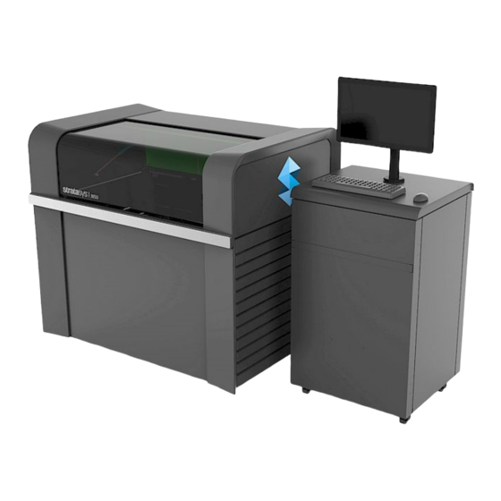
Stratasys J850/J835 User Guide 3 Introducing the Stratasys J850/J835 3D Printer Work Configurations Stratasys J850/J835 3D printing systems can be set up as single-station systems or as multi-station systems. When connected to a local computer network, the system can serve multiple users. In such configurations, each user (client) prepares files f or production. A software service, installed on the printer computer, processes jobs and controls the printing. Figure 3-1 shows the printer set up in a multi-client configuration. Figure 3-1 Multi-client network configuration DOC-18001 Rev. D... -
Page 20: Source Files
Stratasys J850/J835 User Guide 3 Introducing the Stratasys J850/J835 3D Printer Source Files Stratasys J850/J835 printing systems produce three-dimensional models designed with most CAD tools and some other 3D applications. GrabCAD Print supports STL and, VRML files, and, in addition, native CAD formats from these programs: Creo, SOLIDWORKS, NX, CATIA and Inventor. To see the complete list of file formats supported by GrabCAD Print, go to: help.grabcad.com/print/file-formats. J850/J835 systems feature the capability of producing different types of model files simultaneously. DOC-18001 Rev. D... -
Page 21: Printing Materials
Stratasys J850/J835 User Guide 3 Introducing the Stratasys J850/J835 3D Printer Printing Materials Stratasys J850/J835 printers produce models by jetting thin layers of printing materials on the build tray, until the complete model is formed. Two types of material are used in this process: • Model material—which makes up the finished model • Support material—which fills gaps and spaces in the model during printing, and is removed after printing For up-to-date information about PolyJet printing materials and their properties, go to www.stratasys.com/materials/polyjet. Storage Materials used for printing models with J850/J835 printers are made of resins, which are composed of reactive monomers and oligomers. Although printing materials are supplied in sealed, UV-proof cartridges, care must be taken when storing and handling them. Follow these guidelines to protect operators and the environment, and to ensure optimum results. • To ensure product stability, do not allow these materials to come into contact with metal. Plastics made from monomer-soluble substances (such ... -
Page 22: Disposal
Stratasys J850/J835 User Guide 3 Introducing the Stratasys J850/J835 3D Printer Safety Before being cured, resins are hazardous materials. To prevent possible health Considerations hazards, follow these precautions regarding printing materials: • Do not expose to flames, heat or sparks. • Prevent contact with skin and eyes. • Ventilate areas where they are handled. • Keep them separate from food and drink. Cured plastic parts, however, are safe. They can be handled and stored without precautions. You can find more safety information about resins in: "Safety Guidelines" on page 2-4 "First Aid for Working with Printing Materials" on page 2-7 Disposal Dispose of cartridges of model and support material in accordance with all ... -
Page 23: Starting The P Rinter
Operating and Maintaining the Printer Starting the P rinter Loading Model and Support Cartridges Producing Models Preparing the Printer Starting Printing Printer Interface Color Key Printing Indicators Resuming Production After Printing has Stopped 4-10 Changing the Printing Material 4-13 Changing Model Materials Without Flushing 4-18 Advanced Settings 4-20 Keeping the Printer in Idle Mode 4-24 Shutting Down the Printer 4-25 Maintaining the Printer 4-28 Routine Maintenance Schedule 4-28 Maintenance Counters 4-29 UV Lamp Check 4-31 Pattern Test 4-31 Backing up the Printer Configuration 4-34 Improving Print Quality 4-34 Cleaning the Print Heads, Roller and Wiper 4-35 Cleaning the Roller Waste Collector and Inspecting the Roller ... - Page 24 Replacing the Material Filters 4-86 Replacing the Odor Filter 4-89 Replacing the UV Lamps 4-89 Dynamic Nozzle Test 4-95 Built-in Tests 4-96 Replacing the Waste Container 4-101 Cleaning the Exterior Panels 4-104 Cleaning the UV Screen 4-104 DOC-18001 Rev. D...
- Page 25 Stratasys J850/J835 User Guide 4 Operating and Maintaining the Printer Figure 4-1 The Stratasys J850/J835 3D Printer Starting the Printer Caution Do not attempt to operate the printer before being trained by an authorized Stratasys representative. Observe all safety warnings and follow the safety guidelines described in Chapter 2.
- Page 26 Stratasys J850/J835 User Guide 4 Operating and Maintaining the Printer Figure 4-2 Main power switch and cable 2. After the printer-control computer boots, log in to Windows and launch the printer-control program: A HASP plug containing a valid product activation key is required on the printer computer. This is supplied during printer installation or upgrade. If the application does not open and a HASP message appears, contact your Stratasys dealer or service provider.
- Page 27 The material cabinet contains a module that identifies loaded printing materials. Tampering with this module will render the printer inoperable and may void Stratasys warranties and service contracts. Important: If you need to replace the printing material currently installed with another type, see "Changing the Printing Material"...
- Page 28 Stratasys J850/J835 User Guide 4 Operating and Maintaining the Printer Producing Models Models can be printed after they are arranged on a virtual build tray in the GrabCAD Print application. For information about preparing model files for printing, see the GrabCAD Print online documentation. Preparing the Before beginning to produce models, it is recommended that you check the Printer current printing quality of the print heads by performing a pattern test (see "Pattern Test" on page 4-31). To prepare the printer for producing models: 1. Make sure that the build tray in the printer is empty and clean. If not, remove cured material with the scraper, and clean the tray thoroughly with a wet cleaning cloth. Caution Use protective gloves when cleaning the build tray, and be careful of the sharp edges of the scraper blade.
- Page 29 Stratasys J850/J835 User Guide 4 Operating and Maintaining the Printer You can monitor printer status by switching the printer interface display. To do this, click the display toggle button on the printer interface screen. Figure 4-4 Printer status Starting To begin printing: Printing ➢ On the printer interface, click the red button to switch the printer to online mode. The color of the button changes from red to green (see the figure on page 4-4). I f there is a job in the printing queue, it is sent to the printer. When switching the printer to online mode, a message is displayed if a maintenance activity is required to ensure optimum printing quality.
- Page 30 Stratasys J850/J835 User Guide 4 Operating and Maintaining the Printer printing, the printer interface indicates this (see "Printer Interface Color Key" below). The background colors in the printer indicator fields tell you at a glance Printer whether or not the value or item is suitable or ready for printing. Interface Color Key • Green—suitable/ready for printing For example, in Figure 4-4 on the previous page: ❒ Heads (°C)—The heads have reached the temperature required for printing models. ❒ Ambient—The ambient temperature of the printing chamber is within the acceptable range. ❒ Heads Liquid—The level of Model and Support material in the print-block reservoir is OK. ❒ Heads Vacuum—The vacuum level in the system is within the acceptable range. ❒ Pre-Heater—The Model and Support resins need to be heated before being supplied to the print block. The temperature has reached the acceptable range. • Red—not suitable for printing (or indicates a warning) For example, in Figure 4-4 on the previous page:...
- Page 31 Stratasys J850/J835 User Guide 4 Operating and Maintaining the Printer Printing The printer interface screen changes when you send a print job to the printer, Indicators if the printer is on line: • The mode changes from Pre-print to Printing. • The specific activity being performed is shown in the “current activity” field. • Current job-printing information is displayed. • The printing progress bar is displayed. • The Stop and Pause buttons are enabled. When the weight of a cartridge drops below 100 grams, the display of the material level in the printer interface is red. Figure 4-5 Printer interface during printing DOC-18001 Rev. D...
- Page 32 Stratasys J850/J835 User Guide 4 Operating and Maintaining the Printer Resuming Production After Printing has Stopped If the printing process is interrupted, the print manager stops sending slices to the printer. This can happen, for example, if the printing material runs out in the middle of a print job, and you do not replace the empty cartridge immediately. After the printer changes to Standby or Idle mode, you need to resume printing from the print manager in GrabCAD Print. After printing stops, the printer goes into Standby mode, when heating of the print heads is reduced. About 10 hours later, the printer goes into Idle mode, when heating of the print heads is stopped.
- Page 33 Stratasys J850/J835 User Guide 4 Operating and Maintaining the Printer Figure 4-7 Printer interface after interrupted printing 5. If, for any reason, the correct number does not appear in the dialog box, enter the number and click OK. You cannot continue printing the model if: • The number of the last slice printed does not appear in the printer interface, even if the server computer displays the c onfirmation dialog box. • There was a relatively long interruption in printing, even if the “last slice” and i ndicators are correct. The part of the model already printed may deform or shrink, and there might be a visible difference between it and the newly printed part. The effects of a printing stoppage on a model depend on the model size and structure, Model material used, ambient temperature and the length of the stoppage. DOC-18001 Rev. D 4-11...
- Page 34 Stratasys J850/J835 User Guide 4 Operating and Maintaining the Printer If you cannot continue printing: 1. Cancel the job in GrabCAD Print. In the Schedule screen: ❒ Right-click on the job to display the pop-up menu, and select Cancel job. OR— ❒ Left-click on the job to display the Job Status details, and click the Cancel i con . 2. Remove the partially printed model from the build tray. 3. Click to resend the job to the printer. You can stop printing from either the printer interface or from GrabCAD Print.
- Page 35 Stratasys J850/J835 User Guide 4 Operating and Maintaining the Printer Changing the Printing Material Before producing models using a different type of printing material than is currently installed, run the Material Replacement wizard to flush the print block and feed tubes. After using the wizard to change the Support material and certain Model materials, Head Optimization is required before printing models. You should carefully plan printing models with different materials to avoid unnecessary waste of the materials currently loaded.
- Page 36 Stratasys J850/J835 User Guide 4 Operating and Maintaining the Printer 4. Choose the configuration for producing models: ❒ 7 Materials (High Mix / High Quality) ❒ 3 Materials (High Speed) ❒ Single Material (Super High Speed) Figure 4-9 Material Replacement Options 7 Materials Each print head is loaded with two different materials. Figure 4-10 Seven Model materials loaded in the print heads You can print with any single material, or with a combination of them. High-speed printing is not available, but high-quality models can be printed. DOC-18001 Rev. D...
- Page 37 Stratasys J850/J835 User Guide 4 Operating and Maintaining the Printer 3 Materials Both sections of each print head are loaded with t he same material. Figure 4-11 Three materials loaded in the print heads Up to three Model materials are available, with high-speed printing. Single Material Both sections of two print heads are loaded with t he same Model material—DraftGrey (RGD750). Both sections of two print heads are loaded with Support material. Figure 4-12 One Model material loaded in the print heads This mode produces build trays with DraftGrey material, in Super High ...
- Page 38 Stratasys J850/J835 User Guide 4 Operating and Maintaining the Printer 7. For Support material, select t he number of cartridges to replace. ❒ In High Mix / High Quality and High Speed modes, you can print using one or two Support cartridges. ❒ In Super High Speed mode, at least two Support cartridges are required; you can print with up to four Support cartridges. 8. If the color or mechanical properties of the first printed models are unimportant, and if you did not change the printing mode (High Quality/Speed) you can replace the Model materials without flushing out the current materials. To do so, continue with " Changing Model Materials Without Flushing" on page 4-18. 9. To flush out material currently in the system, choose the flushing cycle that fits your needs: The default flushing cycle is the one used for the last material replacement.
- Page 39 Stratasys J850/J835 User Guide 4 Operating and Maintaining the Printer 10. Click Next to begin the material replacement process in the printer. The Cartridge Positioning screen appears, showing you the new location of all cartridges in the material cabinet. Figure 4-13 Cartridge placement Symbols: The correct cartridge is in this slot. No cartridge (or the incorrect cartridge) is in this slot. The cartridge in this slot has insufficient weight to complete the material replacement process. The expiration date of the cartridge in this slot has passed. 11. Replace material cartridges as necessary, according to the instructions in the wizard screen. 12. Click Start. 13. Read the warning message, and click OK. If you continue, you must complete the material replacement process before you can produce models. To replace material cartridges at another time, click Cancel.
- Page 40 Stratasys J850/J835 User Guide 4 Operating and Maintaining the Printer Before printing models, you need to run the Head Optimization wizard in these cases: • after changing the type of Support material (SUP705/706) • after replacing Vero with ABS-like or Agilus30 Model materials (and the reverse) See "Optimizing (Calibrating) Print Heads"...
- Page 41 Stratasys J850/J835 User Guide 4 Operating and Maintaining the Printer 3. When the Material Replacement Options screen opens, select the Replace materials without flushing check box and click Next. Figure 4-15 Replace materials without flushing 4. In the confirmation message that appears, click Yes to continue. Figure 4-16 Replace without flushing confirmation message DOC-18001 Rev. D 4-19...
-
Page 42: Advanced Settings
Stratasys J850/J835 User Guide 4 Operating and Maintaining the Printer 5. In the Cartridge Positioning and Process Progression screen, click Start. Figure 4-17 Cartridge Positioning and Process Progression screen 6. Read the Warning message that appears, and click OK to continue. Figure 4-18 Warning message Material replacement begins. Advanced The Advanced Settings dialog box enables you to configure the Material Settings Replacement wizard for special purposes. If necessary, click Advanced Settings in the Material Replacement Options screen before clicking Next. - Page 43 Stratasys J850/J835 User Guide 4 Operating and Maintaining the Printer To select the slots for the cartridges manually: 1. In the Material Replacement Options screen, click Advanced Settings. 2. In the Advanced Settings screen, select Manual slot selection, and click Apply. Figure 4-19 Manual slot selection 3. In the Material Replacement Options screen, Both cartridges is selected ...
- Page 44 Stratasys J850/J835 User Guide 4 Operating and Maintaining the Printer When printing in High Speed mode (three materials), the same material is used in both sections of each print head. The material selected for one of the cartridge slots is also used in the other print head channel. Figure 4-21 Manual cartridge selection—3 Model Materials 4. After selecting the materials for the appropriate cartridge slots, the Cartridge Positioning screen appears. Place the cartridges in the materials cabinet as shown in this screen. Figure 4-22 Cartridge Positioning screen (High Speed mode) DOC-18001 Rev. D 4-22...
- Page 45 Stratasys J850/J835 User Guide 4 Operating and Maintaining the Printer Additional The flushing cycle you select in the Material Replacement Options screen Flushing Cycles determines how thoroughly to flush out material currently in the system. After selecting the Economy cycle and completing the wizard, you might decide that you require a more thorough flushing, to ensure accurate model color. Or, you may notice that printed models are not satisfactory because they contain traces of the previous material. If so, you can flush out more material, so that the next models will be printed with pure material. To perform additional flushing cycles: ➢ In the Advanced Settings screen, select Enable "flush again" options and click Apply. Figure 4-23 Enable flush again options selected The Material Replacement Options screen appears, where you can select the ...
- Page 46 Stratasys J850/J835 User Guide 4 Operating and Maintaining the Printer Keeping the Printer in Idle Mode Between printing jobs, the printer can be left unused for up to one week. If the printer will not be used for more than a week, use the Shutdown wizard to automatically perform the procedures that must be done before turning off the printer (see "Shutting Down the Printer" on the next page). When the printer stops producing models, the printer software automatically reduces the temperature of the print heads, as follows: After printing stops Mode Change in heating of print heads first 15 minutes Standby 1 no change next 1 minute...
- Page 47 Stratasys J850/J835 User Guide 4 Operating and Maintaining the Printer Shutting Down the Printer You only need to shut down the printer if it will not be used for a week or more. Otherwise, the printer can remain on, in Idle mode. The Shutdown process flushes printing materials from printer components. To avoid flushing out valuable material, make sure to print models at least once a week. Many printer operators use this opportunity to print customer samples or test models.
- Page 48 Stratasys J850/J835 User Guide 4 Operating and Maintaining the Printer 3. Select the option corresponding to the length of time that the printer will not be used—less or more than 30 days. Note: Before selecting More than 30 days, make sure that cleaning-fluid cartridges are available. Figure 4-25 Shutdown options 4. In the next screen, verify that the tray is empty and click Next. ...
- Page 49 Stratasys J850/J835 User Guide 4 Operating and Maintaining the Printer 6. When the final wizard screen appears, close the printer-control application and shut down the printer computer. Figure 4-28 Final Shutdown wizard screen 7. After the printer computer shuts down, turn off the main power switch at the back of the printer ( see Figure 4-2 on page 4-4). DOC-18001 Rev. D 4-27...
- Page 50 Stratasys J850/J835 User Guide 4 Operating and Maintaining the Printer Maintaining the Printer Performing routine maintenance tasks is essential for getting satisfactory results from your printer. Perform the tasks at specified intervals. Routine Frequency Task For More Maintenance Information Schedule Before printing Clean the UV lamp lenses. Before / after printing Check the UV lamp overheating indicator.
- Page 51 Stratasys J850/J835 User Guide 4 Operating and Maintaining the Printer Frequency Task For More Information Monthly Remove and clean the print-head splash See "Cleaning shield. the Print-Head Splash Shield" on page 4-49. Monthly Clean debris from the Z-axis shaft with a vacuum cleaner.
- Page 52 Stratasys J850/J835 User Guide 4 Operating and Maintaining the Printer If there is a maintenance task due, this is indicated on the main interface screen. Figure 4-30 Maintenance Required indicator If this indicator appears, you can display the Maintenance Counters screen by clicking on it. Figure 4-31 Maintenance Counters screen The Maintenance Required indicator appears by default for most operator- performed maintenance tasks. The check box under “User Warning” controls whether or not it appears when a particular task is due.
-
Page 53: Pattern Test
Stratasys J850/J835 User Guide 4 Operating and Maintaining the Printer UV Lamp A heat-sensitive label is fixed to the UV lamp covers as a warning against Check overheating. Its center changes from white to black if the temperature of the cover reaches 65°C (150°F). If this occurs, do not use the printer, and call your service provider. As a precaution, it is recommended that you check the label before and after printing. Figure 4-32 Heat-sensitive label on UV lamp cover If the UV lamp continues to overheat, and the temperature around the lamp reaches 90°C (194°F), a heat fuse turns off the electricity to the power to the UV lamp and the motors for the X, Y, and Z axes. - Page 54 Stratasys J850/J835 User Guide 4 Operating and Maintaining the Printer Figure 4-33 Selecting Pattern Test 5. Click Yes in the Confirm dialog box to begin. Figure 4-34 Pattern Test confirmation 6. If the build tray is not clear, click No in the following dialog box. Figure 4-35 Build tray (Z) level adjustment The build tray is lowered so to prevent damage to models on the tray. DOC-18001 Rev. D 4-32...
- Page 55 Stratasys J850/J835 User Guide 4 Operating and Maintaining the Printer The printer prints a series of lines on the test paper (see next figure). Figure 4-36 Sample Pattern Test 7. Carefully inspect the test paper to see if there are missing lines. Too many missing lines, especially if they are in the same area, indicates that the quality of printing when producing models will be poor. If this is the case, see "Improving Print Quality" on the next page. Note: Acceptable model quality is subjective, and depends on the type and scale (size) of the models produced. As a rule, however, more than 10 missing lines in one area of a column is considered unacceptable.
-
Page 56: Backing Up The Printer Configuration
Stratasys J850/J835 User Guide 4 Operating and Maintaining the Printer Backing up the It is recommended that you periodically back up the printer's configuration Printer files. In case of printer malfunction or the need to re-install the software on Configuration the printer computer, parameters can be restored from the backup. The backup also saves the printer's log and the calibration and maintenance history. To back up the printer configuration files: 1. From the Options menu, select Collect Service Data. or— Press F2. Figure 4-37 Selecting Collect Service Data from the Options menu 2. ... -
Page 57: Cleaning The Print Heads, Roller And Wiper
Stratasys J850/J835 User Guide 4 Operating and Maintaining the Printer If the results of the pattern test are still poor: 1. Carefully clean the print heads again, making sure there is no residue left on them. 2. Perform the purge sequence. 3. Perform the pattern test. If the results of the pattern test are still poor: ➢ Optimize the print heads and replace faulty print heads, if necessary (see "Optimizing (Calibrating) Print Heads" on page 4-51). - Page 58 Stratasys J850/J835 User Guide 4 Operating and Maintaining the Printer 3. Make sure that the build tray is clear (empty), and close the cover. Confirm this in the wizard screen and click Next. Figure 4-39 Preparation check The printer moves components to the cleaning position. 4. When the following screen appears, open the printer. Figure 4-40 Wizard screen during cleaning tasks Warning: Hot Surface The print head orifice plates (bottom surface) may be hot. Do not touch them with your bare hands, and proceed with caution.
- Page 59 Stratasys J850/J835 User Guide 4 Operating and Maintaining the Printer 8. Clean the orifice plates, with a back-and-forth motion. Use the mirror to make sure that you have removed all of the residue material. Figure 4-41 Cleaning the heads Once a month, remove and clean the print-head splash shield. (See step 4 on page 4-50.) 9. Clean the glass lens on the UV lamps. 10. Using the alcohol-soaked cleaning cloth, remove any material remaining on the wiper and the surrounding area. 11. Remove any pieces of waste material collected in the purge unit. If necessary, remove the waste collector to clean it. Wipe the rubber seal.
- Page 60 Stratasys J850/J835 User Guide 4 Operating and Maintaining the Printer 12. Inspect the wiper. If the wiper is scratched, torn or worn, or if you cannot clean it completely, replace it. a. Grasp it and pull it up and out of its bracket. b. Insert the new wiper blade, making sure that it is straight and secured well on both sides. 13. Select the confirmation check boxes in the wizard screen (see Figure 4-40) and click Next. 14. Activate the roller, so that it rotates while you clean it. Figure 4-43 Roller-rotation activation 15. With a cleaning cloth soaked with alcohol, clean the roller surface, as it is rotating. Caution Use caution when cleaning the rotating roller. Use a cleaning cloth or the supplied UV cleaning pad.
- Page 61 Stratasys J850/J835 User Guide 4 Operating and Maintaining the Printer 17. Remove the cleaning materials from the printer and close the printer cover. 18. Select the confirmation check boxes in the wizard screen and click Next. The head-purge cycle begins. When this is complete, the final wizard screen appears. Figure 4-45 Cleaning wizard—final screen 19. Click Done to close the wizard. Cleaning the The roller waste collector removes waste material scraped from the roller. Roller Waste Suction removes this waste to the printer’s waste container. Collector and This assembly should be cleaned weekly to prevent a blockage in the tubes Inspecting the leading to the waste container, so that waste material does not overflow into Roller Scraper the printer. To clean the roller waste collector: 1. ...
- Page 62 Stratasys J850/J835 User Guide 4 Operating and Maintaining the Printer 3. Remove the right UV-lamp assembly: a. Disconnect the UV power cable and the fan power cable. Figure 4-46 Disconnecting the right UV assembly b. Remove the screw that secures the right UV lamp, and then pull and lift up the UV lamp. 4. Loosen the two screws securing the suction tube on the print block. Figure 4-47 Lifting the suction tube 5. Lift the suction tube to secure it in a raised position. DOC-18001 Rev. D 4-40...
- Page 63 Stratasys J850/J835 User Guide 4 Operating and Maintaining the Printer 6. Remove the two screws securing the covering of the roller waste collector and remove it. Be very careful to save the covering screws. These are special screws; if they are lost, you need to order replacements. Figure 4-48 Removing the roller waste collector screws 7. ...
-
Page 64: Cleaning The Roller Waste Collector And Inspecting The Roller Scraper
Stratasys J850/J835 User Guide 4 Operating and Maintaining the Printer 6. Before returning the roller waste collector to the print block, make sure that the pins are clean. Figure 4-50 Roller waste collector pins To re-assemble the components: 1. Return the roller waste collector to the print block and screw on the covering (see Figure 4-48 on the previous page). 2. Loosen the screws securing the suction tube. Figure 4-51 Positioning the suction tube 3. Lower the suction tube so that the hole in the panel behind the tube is visible, and tighten the screws to secure the tube. 4. Attach the right-UV-lamp assembly to the print block and reconnect the UV power and fan cables. - Page 65 Stratasys J850/J835 User Guide 4 Operating and Maintaining the Printer To replace the roller scraper: 1. Prepare— ❒ a new roller scraper blade ❒ a Phillips 1x75 mm screwdriver ❒ a 2.5-mm and a 2-mm hex (Allen) key 2. Remove the right UV lamp and the roller waste collector covering (see steps 3 to 6 on page 4-40). 3. Loosen the two screws securing the roller waste collector and pull it out. Figure 4-52 Removing the roller waste collector 4. Remove the screws that secure the roller scraper assembly. Figure 4-53 Removing the roller scraper screws 5. ...
- Page 66 Stratasys J850/J835 User Guide 4 Operating and Maintaining the Printer 6. Place the new scraper blade onto the pins in the holder, as shown. Figure 4-55 Inserting the new roller scraper blade 7. Insert and tighten the roller scraper blade screws. Important: Tighten the screws in the order shown in Figure 4-56. Use the new screws supplied in the replacement kit Figure 4-56 Tightening the roller scraper screws 8. ...
- Page 67 Stratasys J850/J835 User Guide 4 Operating and Maintaining the Printer Aligning the You should check the alignment of the print heads— Print Heads • once a month • after replacing one or more heads • if model quality is not acceptable even after cleaning the orifice plate on the bottom of the print block (see "Cleaning the Print Heads, Roller and Wiper" on page 4-35). This procedure takes about 20 minutes. To check the alignment of the print heads: 1. Prepare— ❒ a transparency sheet, A-4 or Letter size ❒ any type of adhesive tape, to fasten the transparency sheet to the build tray 2. Start the Head Alignment wizard from the Options menu. 3. Close the cover and click Next to begin.
-
Page 68: Aligning The Print Heads
Stratasys J850/J835 User Guide 4 Operating and Maintaining the Printer 8. If the printer is currently loaded with seven Model materials, (High Mix / High Quality mode), select the mode for aligning the print heads. Figure 4-59 Mode selection When you click Next, the printer prints the head alignment test on the transparency. When printing is finished, the following screen appears. Figure 4-60 Head Alignment wizard—steps 9–11 9. Open the printer and remove the transparency. The transparency sheet is printed with sets of vertical lines in seven columns, each showing the results from a different print head. Figure 4-61 Sample head-alignment test Note: There is no column for head H7 because its alignment is used as a reference for aligning all other heads. - Page 69 Stratasys J850/J835 User Guide 4 Operating and Maintaining the Printer 10. For each column of lines, use a magnifying glass or loupe to inspect pairs of consecutive rows printed on the transparency to see where the vertical lines align. Figure 4-62 Comparing rows of alignment lines Note: It does not matter which pair of lines you inspect, since they were all printed by the same head. Choose a pair of clearly printed lines for the inspection.
- Page 70 Stratasys J850/J835 User Guide 4 Operating and Maintaining the Printer 13. Click Next to display the next head alignment screen, and again select the number representing the most closely aligned vertical lines on the transparency for that print head. When you have finished aligning all of the heads, the following screen is displayed. Figure 4-64 Parameter update confirmation 14. Continue as follows: ❒ To make the alignment changes in the printer, make sure that Update system with new parameters is selected, and click Next. ❒ To recheck the alignment test results before making the alignment changes in the printer, click Previous. ❒ If you do not want to make alignment changes in the printer at this time, select Keep previous parameters, and click Next. 15. In the following screen, you can choose to either repeat the head alignment procedure or close the wizard. Figure 4-65 Repeat head alignment option ❒ ...
-
Page 71: Cleaning The Print-Head Splash Shield
Stratasys J850/J835 User Guide 4 Operating and Maintaining the Printer Cleaning the To prevent excess printing material from accumulating around the print Print-Head heads, a splash shield is installed on the bottom of the print block. Remove Splash Shield the shield and clean it once a month, when cleaning the print heads (see "Cleaning the Print Heads, Roller and Wiper" on page 4-35). To remove the print-head splash shield: 1. Run the Cleaning wizard from the Options menu. When the printer moves components to the cleaning position, the following screen appears. Figure 4-66 Wizard screen during cleaning tasks 2. Open the printer and place a mirror on the build tray. 3. Put on cleaning gloves. - Page 72 Stratasys J850/J835 User Guide 4 Operating and Maintaining the Printer 4. Using a 2-mm hex (Allen) key, remove the screws to remove the splash shield. Figure 4-67 Print-head splash shield installed on the print block Figure 4-68 Removing the print-head splash shield Warning: Hot Surface The print head orifice plates (bottom surface) may be hot. Do not touch them with your bare hands, and proceed with caution.
-
Page 73: Optimizing (Calibrating) Print Heads
Stratasys J850/J835 User Guide 4 Operating and Maintaining the Printer Optimizing The condition of the print heads directly affects the quality of printed models. (Calibrating) To maintain optimum printing, you should routinely test the print heads, and Print Heads calibrate them to the best working configuration possible by running the Head Optimization wizard every 300 hours of printing. You also need to calibrate the print heads after changing the printing mode between High Mix / High Quality and one of the high-speed modes. During this procedure, you place a scale on the build tray and connect it to the printer. Printing material (resin) is jetted from each head and its weight is automatically recorded and the wizard determines how to optimize the print heads. If, during the optimization process, the wizard determines that a print head is faulty—or that it is negatively affecting layer uniformity with the current head configuration—the wizard instructs you to replace it. If this happens, you can continue the wizard to replace the print head, or abort the wizard, to replace the head at another time. Run the Head Optimization wizard every 300 hours of printing or whenever... - Page 74 Stratasys J850/J835 User Guide 4 Operating and Maintaining the Printer 2. Start the Head Optimization wizard from the Options menu. Figure 4-69 Starting the Head Optimization wizard 3. In the opening wizard screen, click Next to begin. The Wizard Conditions screen appears. 4. Read the conditions, select I Agree and click Next. 5. In the following screen, select Continue with Head optimization if you have recently cleaned the print heads. Otherwise, cancel the wizard and run the Cleaning wizard. Figure 4-70 Clean print heads screen DOC-18001 Rev. D...
- Page 75 Stratasys J850/J835 User Guide 4 Operating and Maintaining the Printer 6. In the following screen, make sure Optimize all print heads is selected, and click Next. Figure 4-71 Procedure selection screen 7. Select the printing mode for which you want to optimize the print heads and click Next. Figure 4-72 Printing mode selection Note: The mode options depend on the materials loaded in the printer.
- Page 76 Stratasys J850/J835 User Guide 4 Operating and Maintaining the Printer 8. Make sure that the build tray is clear and clean, and confirm this in the wizard screen. Figure 4-73 Preparing for head optimization (1) When you click Next, a frame is printed on the build tray. 9. When the following screen appears, open the printer and tape a sheet of pink paper to the surface left of the build tray. Figure 4-74 Preparing for head optimization (2) When you click Next, the Pattern Test is printed on the pink paper. 10. When the following screen appears, open the printer and remove the Pattern Test paper. Figure 4-75 Enter Missing Nozzles screen DOC-18001 Rev.
- Page 77 Stratasys J850/J835 User Guide 4 Operating and Maintaining the Printer 11. Carefully inspect the Pattern Test paper with the Missing Nozzles Ruler to see if there are missing lines. Figure 4-76 Inspecting the Pattern Test Each missing line represents a faulty nozzle in the print head. 12. In the Missing Nozzles screen, enter the number of missing nozzles for each print head and click Next. 13. The wizard continues according to the number of missing nozzles you entered. ❒ If there are too many missing nozzles for acceptable printing, the wizard instructs you to replace the defective print head(s). You can do this now, or abort the wizard. If you are prepared to replace print heads now, the wizard guides you through the procedure when you click Next. Make sure you have replacement heads and the required tools (see page 4-60). Then, continue with "Preparing the Print Block" on page 4-61. Figure 4-77 Head replacement due to missing nozzles ❒ ...
- Page 78 Stratasys J850/J835 User Guide 4 Operating and Maintaining the Printer 14. Set up the scale in the printer by performing the steps listed in the wizard screen. Figure 4-78 Setting up the Head Optimization scale 15. After confirming all of the items listed in the wizard screen, click Next. Printing material (resin) is jetted from each head and its weight is automatically recorded. Then, the following screen appears. Figure 4-79 Emptying the resin container 16. Open the printer. Carefully remove the resin container from the scale and empty it into the purge unit. Then return the container to the scale. Caution: The resin in the container is uncured To prevent contact with skin, wear neoprene or nitrile gloves.
- Page 79 Stratasys J850/J835 User Guide 4 Operating and Maintaining the Printer 18. When the following screen appears, open the printer and remove the scale. Figure 4-80 Remove Scale confirmation screen 19. Confirm the items listed in the wizard screen, and click Next. The wizard uses the data collected to analyze the condition of the print heads and optimize them so they print models with a uniform layer of material. ❒ If the heads are in satisfactory condition, the following wizard screen appears. Figure 4-81 Final wizard screen, after optimizing print heads DOC-18001 Rev. D 4-57...
- Page 80 Figure 4-82 Defective print heads found • Select Replace defective head(s) if you are prepared to replace the print heads now (see below). or— • Select Abort wizard if you want to replace the print heads at another time. Replace print heads only after consulting with an authorized Stratasys service provider. To replace print heads, you need these tools and materials: ❒ replacement print head(s) ❒ 90% isopropanol (IPA—isopropyl alcohol) or ethanol (ethyl alcohol) ❒ disposable cleaning gloves (supplied with the print head; or use any ...
- Page 81 You may need to replace a print head if one or more of the following symptoms occurs: • The Head Optimization wizard determines that a print head is defective. (See "Optimizing (Calibrating) Print Heads" on page 4-51.) • There are noticeable grooves in the surface of printed models. • Visual inspection of the head reveals that its surface is damaged—peeling or bubbles in the nozzle area. • The printer interface displays a warning or malfunction message relating to a print head— ❒ Head Heater temperature timeout ❒ Head Heater thermistor open ❒ Head Heater thermistor short Replace print heads only after consulting with an authorized Stratasys service provider. The Head Optimization wizard guides you through the procedure of replacing a print head, and configures printer components to enable you to perform it. Only replace a print head with the aid of the wizard. The entire print-head replacement procedure takes about 45 minutes, and consists of the following phases: A. Identifying the head(s) needing replacement. This is normally done by the Head Optimization wizard. Otherwise, evidence of physical damage to the head surface or a malfunction message indicates which head needs replacing. B. Preparing the print block for head replacement. This is done automatically when you run the wizard.
- Page 82 Stratasys J850/J835 User Guide 4 Operating and Maintaining the Printer To replace a print head: 1. Prepare— ❒ replacement print head(s) ❒ 90% isopropanol (IPA—isopropyl alcohol) or ethanol (ethyl alcohol) ❒ disposable cleaning gloves (use clean, powder-free gloves) ❒ lint-free cleaning cloths ❒ a mirror ❒ a 3-mm hex (Allen) key ❒ the scale supplied for use in the Head Optimization wizard (Weight Test) ❒ the Missing Nozzles ruler Important: Make sure that you have these items and that the scale is calibrated and fully charged before continuing.
- Page 83 Stratasys J850/J835 User Guide 4 Operating and Maintaining the Printer 6. In the following screen, select Replace faulty heads, and click Next. Figure 4-84 Procedure selection screen Preparing the 7. Select the print head(s) needing replacement, and click Next. Print Block Figure 4-85 Head selection screen The printer heats and empties the print block, and prepares the printer. (This should take up to 15 minutes.) The following screen appears when the printer is ready for you to replace print heads. Figure 4-86 Printer ready for head replacement 8. ...
- Page 84 Stratasys J850/J835 User Guide 4 Operating and Maintaining the Printer Removing the 9. On the front of the print block, loosen the screws that secure the cover Defective Head protecting the print-head driver cards. Figure 4-87 Loosening the driver-card cover screws 10. Lift up the cover. DOC-18001 Rev. D 4-62...
- Page 85 Stratasys J850/J835 User Guide 4 Operating and Maintaining the Printer 11. Loosen the screws that secure the driver-card bracket, and lower the bracket. Figure 4-88 Loosening the driver-card bracket screws 12. Release the driver-card support. Figure 4-89 Releasing the driver-card support DOC-18001 Rev. D 4-63...
- Page 86 Stratasys J850/J835 User Guide 4 Operating and Maintaining the Printer 13. Remove the driver card by releasing the latch at the points shown. Figure 4-90 Releasing the driver-card latch 14. Release the upper and lower screws that secure the print head in the block. (If necessary, you may use a 4-mm hex (Allen) key to loosen the screws.) Figure 4-91 Releasing the print-head locking screws DOC-18001 Rev. D 4-64...
- Page 87 Stratasys J850/J835 User Guide 4 Operating and Maintaining the Printer 15. Press down on the upper and lower locking screws to release the print head, and remove it from the bottom of the print block. Figure 4-92 Releasing the print head 16. Make sure that along with the head, you remove the four (4) rubber O- ring seals. Figure 4-93 O-ring seals on the print head DOC-18001 Rev. D 4-65...
- Page 88 Stratasys J850/J835 User Guide 4 Operating and Maintaining the Printer Important If the seals are not removed with the head, they are probably stuck to the print block housing. If so, remove them. Figure 4-94 Making sure the O-rings are not stuck to the print block Installing the 17. Place four (4) O-ring seals in the replacement head (see Figure 4-93 on the ...
- Page 89 Stratasys J850/J835 User Guide 4 Operating and Maintaining the Printer 22. I n the Replace print heads screen, select the check box to confirm that you have replaced the head(s), and click Next. Figure 4-96 Head replacement confirmation 23. W ith your fingers, make sure that the new head is level and even with the other heads. Figure 4-97 Checking the level of the new head 24. C onfirm that the heads are level by selecting the check box in the following wizard screen, and click Next. Figure 4-98 Installation-check screen DOC-18001 Rev.
- Page 90 Stratasys J850/J835 User Guide 4 Operating and Maintaining the Printer 25. I n the next wizard screen, confirm that you have removed all tools and objects from the printer. Figure 4-99 Cleared-tray confirmation screen 26. C lose the printer cover. The wizard continues by heating the heads, then filling and purging them. If installation problems are detected, the wizard alerts you and instructs you how to continue (see "Installation Problems" below). 27. After replacing print heads, you should run the wizard again, to optimize the new heads, and to make sure that they are optimized for printing with the other heads. In the final wizard screen, select Optimize all print heads and click Next. Figure 4-100 Final wizard Screen Installation If the printer detects that there is a problem after you install print heads, a ...
-
Page 91: Testing And Calibrating The Uv Lamps
Stratasys J850/J835 User Guide 4 Operating and Maintaining the Printer ➢ If the replacement head was not calibrated by Stratasys, remove the head and replace it with another one. Figure 4-101 Invalid-head warning Contact your Stratasys service provider about the uncalibrated head. Testing and The level of UV radiation from the lamps used for curing models can change Calibrating the over time. To ensure optimum curing of models during printing, a pop-up UV Lamps message reminds you to test the lamps and calibrate the level of UV radiation after every 300 hours of printing. You do this by running the UV Calibration Wizard. To measure the UV radiation, you need: • Stratasys TOL-03005-S (UV sensor and cable) or— • a stand-alone UV radiation meter, approved for use with the printer The wizard compares the measured radiation to the recommended radiation level for each of the lamps, at each printing mode—High Speed / High Quality. When calibrating the lamps, the wizard attempts to adjust the radiation level, if necessary. • If the reading is within the acceptable range, the wizard continues to the next phase. ... - Page 92 Figure 4-103 UV device selection UV Measuring Device When you use the Stratasys UV sensor box (TOL-03005-S), you connect it to the printer. The wizard automatically measures and calibrates the UV radiation. If you use a stand-alone UV radiation meter, you need to manually enter the readings from the meter in the wizard screens.
- Page 93 Stratasys J850/J835 User Guide 4 Operating and Maintaining the Printer 4. Make sure that the build tray is empty. Confirm this in the wizard screen and click Next. Figure 4-104 Printer preparation ➢ When using a Stratasys UV sensor box that you connect to the printer (TOL-03005-S), continue with "UV Sensor Connected to Printer" on the next page. ➢ When using a stand-alone UV radiation meter, continue with "External UV Meter" on page 4-73. DOC-18001 Rev. D 4-71...
- Page 94 Stratasys J850/J835 User Guide 4 Operating and Maintaining the Printer UV Sensor The following steps apply when using the Stratasys UV sensor box that you Connected to connect to the printer. They do not apply when using a U V external radiation Printer measuring device. 1. To synchronize the wizard and the UV sensor, enter the CF number from the label on the back of the UV sensor box. Figure 4-105 UV sensor synchronization Figure 4-106 Label on the bottom of the UV sensor box 2. Click Next.
- Page 95 Stratasys J850/J835 User Guide 4 Operating and Maintaining the Printer 3. Open the printer and connect the UV sensor cable to the connector in the printer. 4. Confirm the items listed in the wizard screen and click Next. Figure 4-108 Sensor positioning Continue with "UV Measurement " on page 4-75. External UV The following steps apply when using a stand-alone UV meter. They do not Meter apply when using the Stratasys UV sensor box connected to the printer. 1. When the following screen appears, open the printer and place the UV sensor (probe) at the rear edge of the tray, in the center. Figure 4-109 Sensor placement screen DOC-18001 Rev. D...
- Page 96 Stratasys J850/J835 User Guide 4 Operating and Maintaining the Printer 2. Lead the cable out of the printer so that you can close the printer, and tape it down to make sure that it does not interfere with the moving print block. Figure 4-110 Correct UV-sensor placement 3. Close the printer, while checking that the sensor does not move out of position. 4. Set the UV meter to measure mJ/cm2. 5. Set the range on the meter to 2,000. 6. Connect the cable from the sensor to the UV meter. 7. Turn on the UV meter, and wait until “0 0 0.0” appears on the display. 8. In the wizard screen, confirm that the sensor is positioned correctly, and click Next. Continue with "UV Measurement " on the next page. ...
- Page 97 Stratasys J850/J835 User Guide 4 Operating and Maintaining the Printer The UV lamps power up and stabilize. (This takes several minutes.) Then, the Measurement print block passes over the sensor and the wizard compares the measured radiation to the recommended level for each UV lamp and printing mode. During this process, which takes 20–40 minutes, you need to monitor the progress as displayed in the wizard screen. Figure 4-111 UV measurement progress When using a stand-alone radiation meter (not the Stratasys UV sensor box connected to the printer): Reset the meter and enter the reading (measurement) when you are prompted to do so. Figure 4-112 UV Measurement dialog box If the UV level measured is not acceptable, the wizard calibrates the UV lamp by adjusting the current supplied to it, and then tests it again. When all UV tests have finished, the results are displayed, showing the condition of the lamps after calibration (see Figure 4-113 below). Figure 4-113 Results and condition of UV lamps after calibration DOC-18001 Rev.
- Page 98 Stratasys J850/J835 User Guide 4 Operating and Maintaining the Printer After examining the UV calibration results: 1. Click Next. 2. Remove the UV sensor and close the printer cover. After confirming the items listed in the wizard screen, click Next. Figure 4-114 UVsensor removal If the results are not acceptable for quality printing, this is indicated in the final wizard screen. Figure 4-115 Final UV Calibration Wizard screen DOC-18001 Rev. D 4-76...
-
Page 99: Calibrating The Load Cells
Stratasys J850/J835 User Guide 4 Operating and Maintaining the Printer Calibrating the Load cells are sensors that measure the weight of the material cartridges and Load Cells the waste container in the printer. It is important that you periodically check that the weight measurements are accurate to prevent unnecessary waste of printing materials. It is recommended that you calibrate the load cells once a month. To calibrate load cells: 1. Start the Load Cell Calibration wizard from the Options menu. 2. In the following screen, select one or more load cells that you want to calibrate. Figure 4-116 Load cell selection 3. Remove each selected cartridge from the materials cart, and click Next. 4. In the next wizard screen, observe the numbers and wait until the weight level is relatively stable—two units above or below the average level shown. Figure 4-117 Weight stabilization 5. ... - Page 100 Stratasys J850/J835 User Guide 4 Operating and Maintaining the Printer reminder message appears if 250 printing hours have passed since the print- block heater was last flushed. The time required for completing this procedure depends on the materials loaded in the printer. A time estimation appears in the wizard before starting the flushing process. To flush the Print-block Heater: 1. ...
- Page 101 Stratasys J850/J835 User Guide 4 Operating and Maintaining the Printer Figure 4-120 Manual slot selection 5. When the Material Replacement Options screen opens again, select the following: ❒ 7 materials ❒ Economy Figure 4-121 Selections in the Material Replacement Options screen Make sure that the printer is loaded with the selected materials. This procedure requires seven Model materials to flush all of the channels in the print-block heater.
- Page 102 Stratasys J850/J835 User Guide 4 Operating and Maintaining the Printer 7. In the Cartridge Positioning screen, make sure that the material cartridges are properly positioned. Figure 4-122 Cartridge Positioning screen Symbols: The correct cartridge is in this slot. No cartridge (or the incorrect cartridge) is in this slot. The cartridge in this slot has insufficient weight to complete the material replacement process. The expiration date of the cartridge in this slot has passed. Note: The time needed to complete this process depends on the materials currently loaded in the printer. The estimated time is displayed at the bottom of the Cartridge positioning screen.
- Page 103 Stratasys J850/J835 User Guide 4 Operating and Maintaining the Printer 3. Click Next. 4. In the Cartridge positioning screen, make sure that the material cartridges are properly positioned. Note: The time needed to complete this process depends on the materials currently loaded in the printer. The estimated time is displayed at the bottom of the Cartridge positioning screen.
-
Page 104: Replacing The Waste-Pump Tubes
Stratasys J850/J835 User Guide 4 Operating and Maintaining the Printer Replacing the The tubes that pump waste material from the roller waste collector and the Waste-Pump purge unit should be replaced after 1000 hours of use. After this time, a Tubes counter displays a maintenance alert on the printer interface screen. Figure 4-124 Maintenance alert You can check when the pump tubes need to be replaced in the Maintenance Counters interface. To open the Maintenance Counters interface: ➢ Click on the "Maintenance Required" indicator. or— ➢ From the Options menu, select Maintenance Counters. Figure 4-125 Selecting Maintenance Counters from the Options menu. - Page 105 Stratasys J850/J835 User Guide 4 Operating and Maintaining the Printer Start-up Kit. Additional cassettes can be ordered from your Stratasys service provider. To replace the waste pump tubes: 1. Make sure that the printer is in Idle mode (see the figure on page 4-4). Note: The printer enters Idle mode about 16 minutes after printing stops. To force the printer into Idle mode, close the printer application: From the File menu, click Exit.
- Page 106 Stratasys J850/J835 User Guide 4 Operating and Maintaining the Printer 5. Identify the waste pump that requires tube replacement. Figure 4-129 Waste pumps 6. Unscrew the fittings that connect the waste tubes to the pump. Figure 4-130 Disconnecting a pump tube 7. Remove the part of the fitting remaining on the pump tube, and save it. DOC-18001 Rev. D 4-84...
- Page 107 Stratasys J850/J835 User Guide 4 Operating and Maintaining the Printer 8. When the tubes on both sides of the pump are disconnected, rotate the pump "cassette" assembly counter-clockwise and remove it. Figure 4-131 Rotating the pump cassette 9. Install a new pump cassette. The new cassette contains a new pumping tube. 10. Connect the waste tubes to the new pump cassette. 11. If necessary, replace the pump cassette on the other waste pump. 12. Open the Maintenance Counters screen, scroll down to the General Pumps section, and click Reset for the relevant counter(s) (see Figure 4- 126 on page 4-82). 13. Connect the ground wire to the printer panel and attach the panel to the printer. DOC-18001 Rev. D 4-85...
- Page 108 Stratasys J850/J835 User Guide 4 Operating and Maintaining the Printer Replacing the Filters are installed in the lines that supply Model material t o the print heads. Material Filters To ensure that the heads remain in optimum condition, the filters are replaced by your service provider, as part of the scheduled maintenance routine. However, filters used for certain materials need to be replaced more often. A counter keeps track of the amount of material passing through the filters, and the Maintenance Required indicator appears in the printer interface when it is time to replace a filter. The counter for RGD515 material, for example, is set to notify you after 20 hours of use. This is enough, on average, for about a year of printing. To check the material-filter counters, open the Maintenance Counters screen (see "Maintenance Counters" on page 4-29) and scroll down to the Filters section. Figure 4-132 Maintenance Counters screen, showing material filters The figure above shows that 21 hours of filter time have passed since the left filter was installed, and that it needs to be replaced.
- Page 109 Stratasys J850/J835 User Guide 4 Operating and Maintaining the Printer Caution: The monitor goes blank as soon as the remote desktop link terminates— before computer shutdown. Turning off the printer before computer shutdown can cause damage. 4. Using an 8-mm hex (Allen) key, open the latches that secure the back of the materials cabinet and remove the back of the cabinet. 5. Locate the 10-micron filters, installed for the relevant material.
- Page 110 Stratasys J850/J835 User Guide 4 Operating and Maintaining the Printer 10. Identify the inlet side of the new filter. This is the side showing the part number. A 6mm tube is connected to the inlet. (An 8mm tube is connected to the outlet.) Figure 4-134 Filter showing inlet and outlet sides 11. Attach the inlet side of the new filter to the disconnected tube. Important: To attach the filter, hold the fitting at the end of the feed tube in place and turn the filter.
-
Page 111: Replacing The Odor Filter
Stratasys J850/J835 User Guide 4 Operating and Maintaining the Printer Replacing the If the printer exhaust is not connected to an external ventilation system, a Odor Filter built-in activated-carbon filter removes odors from printing materials. This filter should be replaced regularly (as necessary) to keep your working environment pleasant. This is normally done during the preventive- maintenance service visit. Replacing the The UV lamps used for curing models have a long, but limited, working life. UV Lamps You can test and adjust their effective power with the UV Calibration wizard (see "Testing and Calibrating the UV Lamps" on page 4-69). If you need to replace a UV lamp, follow these instructions: 1. Make sure the printer is in offline mode. Figure 4-135 Offline mode indicator (red) The online/offline button at the bottom of the printer interface should be red. If not, click it to switch the printer to offline mode. Warning Before continuing, make sure that the safety interlock is not defeated, and that the UV lamp is not hot. - Page 112 Stratasys J850/J835 User Guide 4 Operating and Maintaining the Printer 3. Make sure that the build tray is empty, and confirm this in the wizard screen. Then, close the printer, and click Next. Figure 4-137 Tray confirmation The axes move to the “home” position. 4. Select the UV lamp(s) to be replaced and click Next. Figure 4-138 UV lamp selection screen 5. Disconnect the UV-lamp power connector and the UV heat fuse connector. Figure 4-139 Disconnecting the UV lamp Note: Do not disconnect the power connection to the cooling fans.
- Page 113 Stratasys J850/J835 User Guide 4 Operating and Maintaining the Printer 6. Loosen the screw securing the UV lamp cover (A), and pull the cover up (B), then out (C). Figure 4-140 Removing the UV lamp cover 7. Pull the UV lamp reflector out of the UV housing. Figure 4-141 Removing the UV lamp reflector 8. Inspect the new UV lamp reflector, and make sure that a black strip is attached to the inside of it. If not, install one—on the side of the reflector opposite (not next to) the print block. Note: Extra black strips are included in the printer Start-Up Kit. If necessary, you can remove the black strip from the old reflector and install it in the new reflector (as long as the black paint has not faded).
- Page 114 Stratasys J850/J835 User Guide 4 Operating and Maintaining the Printer Warning: Broken UV lamp hazard UV lamps contain mercury. Deal with broken lamps with caution. Ventilate the room thoroughly. Use protective gloves when collecting mercury and lamp components. Remove spilled mercury with a method that prevents the generation of mercury vapor, such as a syringe, packing tape or paper.
- Page 115 Stratasys J850/J835 User Guide 4 Operating and Maintaining the Printer 12. Reconnect the power and heat fuse connectors. Figure 4-144 Connecting the UV lamp 13. In the wizard screen, confirm that you have replaced the UV lamp(s) and that the black strip is attached, then click Next. Figure 4-145 UV-installation confirmation The wizard operates the UV lamps and checks if their power is within the acceptable range for each printing mode. Note: The mode currently being checked appears in the lower-left corner of the printer interface.
- Page 116 Stratasys J850/J835 User Guide 4 Operating and Maintaining the Printer After replacing a UV lamp, it is recommended that you calibrate its power for the various printing modes. The next screen allows you to continue to the UV Calibration wizard (see "Testing and Calibrating the UV Lamps" on page 4-69). Figure 4-147 Calibration selection screen DOC-18001 Rev. D 4-94...
-
Page 117: Dynamic Nozzle Test
Stratasys J850/J835 User Guide 4 Operating and Maintaining the Printer Dynamic Perform the Dynamic Nozzle Test if you suspect that poor quality in printed Nozzle Test models is caused by clogged or faulty nozzles in the print heads—even if this is not indicated by the Pattern Test. The Dynamic Nozzle Test prints eight (8) samples on the build tray, which you can then visually inspect. Printing the samples takes about 20 minutes. To run the Dynamic Nozzle Test: 1. Make sure that the build tray is clear (empty). 2. From the Options menu, select Dynamic Nozzle Test, and then select the appropriate test for the current printing mode. Figure 4-148 Selecting Dynamic Nozzle Test from the Options menu 3. ... -
Page 118: Built-In Tests
• Troubleshooting tips. Running these tests can help identify problems in the printer hardware and software. A large number of hardware defects (or near-defects) warns you of possible printing problems, either for current or future jobs. Stratasys recommends running the built-in tests in the following cases: as a routine test, once every two weeks as a system check, before major (long) jobs as needed, for troubleshooting To open the Built-in Tests screen, do one of the following: • From the Options menu, select Built-In Tests. - Page 119 Stratasys J850/J835 User Guide 4 Operating and Maintaining the Printer The Built In Tests screen lists pre-configured tests, grouped by component categories. In this screen, you select and run tests, and the results are displayed. Figure 4-151 Built In Tests screen Test Name Test List This column lists all of the tests, together with selection check boxes. Click the check boxes to select the tests you want to run. To remove a selection, click the check box again. To quickly select all of the tests in a component category, use the Group drop-down list at the bottom of the screen. Group This column shows the component categories for each test. This tells you which tests are run when selecting a category from the Group drop-down list at the bottom of the screen. Status This column shows the results of each test after you run it: Test successfully completed. Test failed. (Double-click on a failed test’s line to review the failure details.) Unknown results.
- Page 120 Stratasys J850/J835 User Guide 4 Operating and Maintaining the Printer Test Selection Area In the Test Selection area, at the bottom of the screen, you can quickly select or de-select tests by their characteristics: Click to select all of the tests in the list. None Click to de-select all of the tests in the list. Unknown Click to select all test that have not been run yet (Status = ?).
- Page 121 Stratasys J850/J835 User Guide 4 Operating and Maintaining the Printer Close Click to close the Built-in Tests screen. Summary On the right side of the screen, a symbol represents the combined results of all the tests run, using the symbols from the Status column. All tests successfully completed. At least one test failed. Not all tests performed. Test The following table lists the name of each test in the Built-in Tests suite, Descriptions and together with its description and a possible reason for its failure. If you need Troubleshooting assistance, contact your Stratasys service provider. Test Name Description...
- Page 122 Stratasys J850/J835 User Guide 4 Operating and Maintaining the Printer Test Name Description Possible Reason for Failure System Voltages Checks if the following voltages are • VPP power supply: within 5% of the required voltage: Faulty head driver. • 40V to the print heads by the VPP •...
-
Page 123: Replacing The Waste Container
Stratasys J850/J835 User Guide 4 Operating and Maintaining the Printer Replacing the Printer waste contains partially cured polymeric material, collected during Waste normal operation and maintenance of the printer. For safety and Container environmental reasons, this material is kept in a special leak-proof, disposable container. The container has a capacity of 10 kilograms of waste material—usually enough for several months of printer use. The printer application displays a warning message when there are 9 kilograms of material in the container, and stops the printing when the net weight reaches 9.5 kilograms. Above 9 kilograms, the software does not allow you to start a printing job or activity until you replace the waste container. You can monitor the weight of the waste container in the Printer Indicators display in the printer interface. You can also visually inspect the level of waste in the container. To access it, see page 4-102. To monitor the waste weight (and other indicators) in the printer: ➢ In the main printer interface screen, click the display toggle to view the ... - Page 124 Stratasys J850/J835 User Guide 4 Operating and Maintaining the Printer The waste container consists of a plastic container inside a cardboard box. You typically dispose of the entire waste container—including the box. Therefore, you must assemble a new box and insert a new plastic container before you can install it in the printer. Replacement boxes, plastic containers, and sealing caps are supplied in the printer start-up kit and in the preventive-maintenance kit. To prepare a new waste container: 1. Assemble the cardboard box, making sure to punch out the perforated ...
- Page 125 Stratasys J850/J835 User Guide 4 Operating and Maintaining the Printer 9. Close the waste compartment door. Dispose of the full waste container in accordance with environmental and safety requirements. DOC-18001 Rev. D 4-103...
- Page 126 Stratasys J850/J835 User Guide 4 Operating and Maintaining the Printer Cleaning the The painted exterior plastic panels of the printer has a durable finish, offering Exterior Panels excellent chemical resistance to common cleaning materials. Follow the recommendations below when cleaning these areas of the printer. Acceptable Cleaning Agents • mild soap solution • common household cleaners and window cleaners • common commercial and industrial detergents, 5% solution in water • alcohol (ethanol, isopropanol), 10% to 40% solution in water Wipe the exterior of the printer, using a soft cloth moistened with the cleaning solution. Unacceptable Materials • industrial solvents • cleaning agents containing hydrocarbons, ketones, esters and lacquer thinners • spray disinfectants • abrasives and agents which could wear away the panel finish The transparent section of the cover is made of strong, acrylic material that Cleaning the screens out harmful UV radiation. Use extreme care when cleaning it to UV Screen prevent the appearance of scratch marks. Caution Do not use abrasive cleaners or cleaning fluids containing ammonia, alcohol, acetone, benzine, carbon or tetrachloride.
-
Page 127: Removing Models After Printing
Handling Printed Models Removing Models After Printing Removing the Support Material Post-Printing Treatment Models made with VeroClear Photo-Bleaching Instructions Storing Models DOC-18001 Rev. D... - Page 128 For special printing applications, refer to documents on the Stratasys Support Center (especially under PolyJet Support Materials) or consult a Stratasys 3D printing expert. There are two types of Support material available: • SUP705 (FullCure705), a gel-like Support material. • SUP706, an easily removed Support material that dissolves in a solution of caustic soda and sodium metasilicate. SUP705 (FullCure705) and SUP706 can be removed from printed models using the following methods, in this order: 1. by hand 2. water pressure (in a suitable cleaning unit) 3. SUP705: 1% caustic soda solution (recommended for a smooth finish) SUP706: 2% caustic soda and sodium metasilicate solution...
- Page 129 Stratasys J850/J835 User Guide 5 Handling Printed Models Removing While wearing protective gloves, break away excess Support material on the Support Material outside of the model. For delicate models, use a toothpick, pin or small brush by Hand after dipping the model in water. • For SUP705, after breaking away excess Support material, soak the model in a 1% caustic soda solution (see "Removing SUP705 with Caustic Soda" on page 5-4). • For SUP706, after breaking away excess Support material, soak the model in a 2% caustic soda and sodium metasilicate solution (see "Removing SUP706 with Caustic Soda and Sodium Metasilicate" on the next page). Removing For most models, the most efficient way to remove Support material is by Support Material using a high-pressure water jet. One suitable system is the Balco WaterJet with Water cleaning unit. This device is marketed by Stratasys. Pressure Figure 5-1 Balco WaterJet Cleaning Unit To clean a model using this device, you place it in the chamber, and you manipulate it and the jet using the built-in, waterproof sleeves. A pump turns ...
- Page 130 Stratasys J850/J835 User Guide 5 Handling Printed Models Removing Soak models in a 1-percent solution of caustic soda (sodium hydroxide) to SUP705 with remove Support material from difficult-to-reach areas and to give the model a Caustic Soda smooth, clean finish. The amount of time you soak the model in the solution depends on how delicate it is and how much Support material needs to be removed, but it is typically between half-an-hour and several hours. In any case, you should remove as much Support material as possible before the caustic soda treatment, and rinse the model thoroughly (with a water jet) afterwards. Warning Caustic soda may cause chemical burns, scarring and blindness. Mixing it with water generates heat that could ignite other materials. Never pour water into caustic soda.
-
Page 131: Post-Printing Treatment
Stratasys J850/J835 User Guide 5 Handling Printed Models Post-Printing Treatment Post-printing treatment is recommended for models printed with several special-purpose materials or for special applications. You can find recommendations for treating and finishing models after printing on the Stratasys Support Center. Models made with VeroClear (RGD810) and VeroUltraClear (RGD820) have a Models made slight yellow tint when removed from the printer. This is especially true for with VeroClear models printed with a glossy finish. The yellow tint fades naturally over time, but you can greatly accelerate this process by using a suitable photobleaching treatment. As a rule, best clarity is achieved when parts are printed with a matte finish, and treated as explained below. Photobleaching models involves exposing them to intense light. To achieve highly controlled and predictable results, a professional illumination chamber is recommended. However, adequate results may be obtained using an illumination chamber that you can construct from readily-available materials. Figure 5-2 Illumination chamber Photo-Bleaching Instructions are on the next page. -
Page 132: Storing Models
❒ For parts with a matte finish, this should be enough. Polish and lacquer the parts. ❒ For parts with a glossy finish, continue the photobleaching treatment for up to 18–24 hours. In Stratasys laboratories, there was a tint reduction of approximately 70% within six hours. After 24 hours, tint was reduced by approximately 90%. More information about photobleaching printed models is available on the Transparent materials page of the Stratasys Support Center, under Documentation > Best Practices. Refer to: VeroClear RGD810 VeroUltraClear RGD820 Storing Models Models are cured as they are printed, making them safe and stable for a long ...
Need help?
Do you have a question about the J850 and is the answer not in the manual?
Questions and answers