Sign In
Upload
Download
Table of Contents
Contents
Add to my manuals
Delete from my manuals
Share
URL of this page:
HTML Link:
Bookmark this page
Add
Manual will be automatically added to "My Manuals"
Print this page
×
Bookmark added
×
Added to my manuals
Manuals
Brands
Stratasys Manuals
3D Printers
J750
User manual
Stratasys J750 User Manual
3d printing system
Hide thumbs
Also See for J750
:
User manual
(173 pages)
,
User manual
(126 pages)
1
2
3
Table Of Contents
4
5
6
7
8
9
10
11
12
13
14
15
16
17
18
19
20
21
22
23
24
25
26
27
28
29
30
31
32
33
34
35
36
37
38
39
40
41
42
43
44
45
46
47
48
49
50
51
52
53
54
55
56
57
58
59
60
61
62
63
64
65
66
67
68
69
70
71
72
73
74
75
76
77
78
79
80
81
82
83
84
85
86
87
88
89
90
91
92
93
94
95
96
97
98
99
100
101
102
103
104
105
106
107
108
109
110
111
112
113
114
115
116
117
118
119
120
121
122
123
124
125
126
127
128
129
130
131
132
133
134
135
136
137
138
139
140
141
142
143
144
145
146
147
148
149
150
151
152
153
154
155
156
157
158
159
page
of
159
Go
/
159
Contents
Table of Contents
Bookmarks
Table of Contents
Table of Contents
1 About this Guide
Using this Guide
For more Information
Revision History
Terms Used in this Guide
Additional Resources
Stratasys Academy
Stratasys Support Center
Grabcad Community
2 Safety
Safety Features
Symbols and Warning Labels
Safety Guidelines
Printer Installation
Printer Operation
UV Radiation
Printer Maintenance
Model and Support Materials
UV Lamps
First Aid for Working with Printing Materials
Contact with Skin
Contact with Eyes
Ingestion
Inhalation
Waste Disposal
3 Introducing the 3D Printer
Basic Features
Work Configurations
Source Files
Printing Materials
Storage
Shelf Life
Exposure to Light
Safety Considerations
Disposal
Work Environment
Workstation Requirements
4 Operating and Maintaining the Printer
Starting the Printer
Loading Model and Support Cartridges
Producing Models
Preparing the Printer
Starting Printing
Printer Interface Color Key
Printing Indicators
Resuming Production after Printing Has Stopped
Changing the Printing Material
Changing Model Materials Without Flushing
Printing with Bio-Materials
Advanced Settings
Keeping the Printer in Idle Mode
Setting the Cartridge Expiration Alert
Shutting down the Printer
Maintaining the Printer
Routine Maintenance Schedule
Maintenance Counters
UV Lamp Check
Pattern Test
Backing up the Printer Configuration
Improving Print Quality
Cleaning the Print Heads, UV Lamp Glass, Roller and Wiper
Cleaning the Roller Waste Collector and Inspecting the Roller Scraper
Replacing the Roller Scraper
Aligning the Print Heads
Cleaning the Print-Head Splash Shield
Optimizing (Calibrating) Print Heads
Replacing Print Heads
Testing and Calibrating the UV Lamps
Calibrating the Load Cells
Flushing the Print-Block Heater
Replacing the Waste-Pump Tubes
Replacing the Material Filters
Replacing the Odor Filter
Replacing the UV Lamps
Improving Color Uniformity of X-Walls
Dynamic Nozzle Test
Built-In Tests
Replacing the Waste Container
Cleaning the Exterior Panels
Cleaning the UV Screen
5 Handling Printed Models
Removing Models after Printing
Removing the Support Material
Removing Support by Hand
Removing Support with Water Pressure
Removing SUP705 with Caustic Soda
Removing SUP706 with Caustic Soda and Sodium Metasilicate
Post-Printing Treatment
Photobleaching for Transparent Models
Storing Models
Advertisement
Quick Links
1
Printer Maintenance
2
Optimizing (Calibrating) Print Heads
Download this manual
User Guide
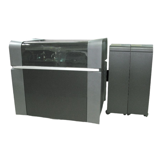
Stratasys J750/J735/J720
3D Printing System
DOC-08040 Rev. R
Table of
Contents
Previous
Page
Next
Page
1
2
3
4
5
Advertisement
Table of Contents
Need help?
Do you have a question about the J750 and is the answer not in the manual?
Ask a question
Questions and answers
Related Manuals for Stratasys J750
3D Printers Stratasys J750 User Manual
(173 pages)
3D Printers Stratasys J750 User Manual
3d printing system (126 pages)
3D Printers Stratasys J850 User Manual
(132 pages)
3D Printers Stratasys J850 User Manual
3d printing system (170 pages)
3D Printers Stratasys J850 Manual
3d printing systems (129 pages)
3D Printers Stratasys J850 User Manual
3d printing system (181 pages)
3D Printers Stratasys J4100 User Manual
3d printing system (136 pages)
3D Printers Stratasys J735 User Manual
3d printing system (159 pages)
3D Printers Stratasys J720 User Manual
3d printing system (159 pages)
3D Printers Stratasys J826 Site Preparation Manual
(21 pages)
3D Printers Stratasys J826 User Manual
3d printing system (170 pages)
3D Printers Stratasys J5 Series User Manual
3d printing system (114 pages)
3D Printers Stratasys J5 Series User Manual
3d printing system (137 pages)
3D Printers Stratasys J3 Series User Manual
3d printing system (118 pages)
3D Printers Stratasys J55 Prime User Manual
3d printing system (137 pages)
3D Printers Stratasys Objet260 Connex User Manual
(198 pages)
This manual is also suitable for:
J735
J720
Table of Contents
Print
Rename the bookmark
Delete bookmark?
Delete from my manuals?
Login
Sign In
OR
Sign in with Facebook
Sign in with Google
Upload manual
Upload from disk
Upload from URL


Need help?
Do you have a question about the J750 and is the answer not in the manual?
Questions and answers