
Related Manuals for PowerLogic EGX200


Summary of Contents for PowerLogic EGX200
- Page 1 63230-314-200/A2 8/2001 Instruction Bulletin POWERLOGIC ® Ethernet Gateway EGX200 Retain for future use.
- Page 2 NOTICE Read these instructions carefully and look at the equipment to become familiar with the device before trying to install, operate, or maintain it. The following special messages may appear throughout this bulletin or on the equipment to warn you of potential hazards or to call attention to information that clarifies or simplifies a procedure.
-
Page 3: Table Of Contents
EGX200 QUICK START CHECKLIST ........ - Page 4 Logging into the EGX200 ........
-
Page 5: Chapter 1-Introduction
EGX200 BOX CONTENTS ........ - Page 6 Chapter 1—Introduction 63230-314-200/A2 Product Description 8/2001 In addition, the EGX200 contains a web server, which lets you remotely configure and troubleshoot both Ethernet and serial communication parameters. A typical application example is shown in Figure 1–1. POWERLOGIC Standard Web System Manager...
-
Page 7: Egx200 Box Contents
• 24 Vdc switching power supply (wall mountable with global plug kit) • EGX200 mounting kit, containing rubber feet and DIN rail adapters • Mounting template • Instruction Bulletin for the installation and operation of the EGX200 and the power supply • Registration card... -
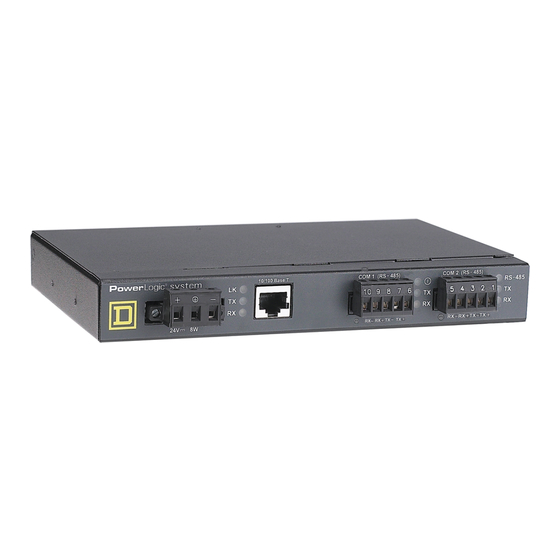
Page 8: Egx200 Components
Table 1–1: EGX200 Components Item Description 1 Control Power Connection 24 Vdc connection for control power to the EGX200. 2 Control Power Connector 3-position male terminal block for 24 Vdc control power connection. LED illuminates yellow steadily when there is a proper Ethernet 3 Ethernet Link LED physical connection. -
Page 9: Chapter 2-Safety Precautions
Consider all sources of power, including the possibility of backfeeding. • Turn off all power supplying the equipment in which the EGX200 is to be installed before installing and wiring the EGX200. • Beware of potential hazards, wear personal protective equipment, and carefully inspect the work area for tools and objects that may have been left inside the equipment. - Page 10 Chapter 2—Safety Precautions 63230-314-200/A2 8/2001 © 2001 Schneider Electric All Rights Reserved...
-
Page 11: Chapter 3-Getting Started
Setup Using HyperTerminal......... . . 13 Accessing the EGX200 Setup Utility....... . . 13... -
Page 12: Egx200 Initial Setup
IP address to match the network configuration. To access the EGX200 Communication Settings web page using a browser, follow these steps: 1. Connect a cross-over Ethernet cable from the EGX200 to the PC, as shown in Figure 3–1. Connect to 24Vdc... - Page 13 Chapter 3—Getting Started 8/2001 EGX200 Initial Setup 2. Power the EGX200 by connecting a 24 Vdc power source to its control power connection. Make sure that the control power is properly Earth grounded (see Control Power Wiring on page 19).
- Page 14 Reboot your PC, if required. 4. Launch a standard web browser such as Internet Explorer. 5. In the browser address field (see Figure 3–4), type the EGX200 IP address (10.10.10.10), and press Enter. Figure 3–4: IP address entered in browser address field...
- Page 15 63230-314-200/A2 Chapter 3—Getting Started 8/2001 EGX200 Initial Setup The EGX200 login page displays, as shown in Figure 3–5. X.XXX Figure 3–5: EGX200 Login page 6. From the Language pull-down menu, select the desired language. 7. In the Password field, type: admin 8.
- Page 16 10. Enter your IP Address, Subnet Mask, and Router IP address, and click Update. 11. Reset your PC back to its original network configuration. Now you are ready to install and use the EGX200 on your Ethernet network. Refer to Chapter 4 and Chapter 5 for more information.
-
Page 17: Setup Using Hyperterminal
Accessing the EGX200 Setup Utility To access the EGX200 setup utility, follow these steps: 1. Attach a null modem cable between the RS-232 COM port (COM 2) of the EGX200 and a Microsoft Windows-based PC, as shown in Figure 3–8. - Page 18 Chapter 3—Getting Started 63230-314-200/A2 EGX200 Initial Setup 8/2001 The Connection Description dialog box displays, as shown in Figure 3–9. Figure 3–9: HyperTerminal Connection Description dialog box 3. In the Name field, enter a descriptive name for your new HyperTerminal connection, and then click OK.
- Page 19 5. In this dialog box, set the values listed in Table 3–3. Table 3–3: Communications Settings Parameters Settings Value Baud Rate 19200 Data Bits Parity None Stop Bits Flow Control None You are now ready to enter the EGX200 setup utility. © 2001 Schneider Electric All Rights Reserved...
- Page 20 LED turns OFF, and you have 5 seconds to press Enter on the PC keyboard to access the EGX200 setup utility. a. Apply power to the EGX200 by wiring the 24 Vdc connector to a power source, or cycle the power.
-
Page 21: Chapter 4-Installation And Wiring
Ethernet LEDs ........... . . 27 MOUNTING LOCATIONS AND INSTALLATION The EGX200 is designed to be set on a flat surface or mounted to a wall, a cabinet, or other surfaces. When choosing a mounting location, consider the following points: •... -
Page 22: Dimensions
Chapter 4—Installation and Wiring 63230-314-200/A2 Mounting Locations and Installation 8/2001 Dimensions Figure 4–1 shows the EGX200 dimensions, including the DIN rail mounting equipment. 1.77 4.81 (45) (123) 1.44 (37) 0.40 7.88 1.07 0.59 (11) (28) (15) 8.68 (221) End View Top View 7.88... -
Page 23: Mounting Options
63230-314-200/A2 Chapter 4—Installation and Wiring 8/2001 Mounting Locations and Installation Mounting Options Figures 4–2, 4–3, and 4–4 illustrate some of the various mounting options. Wall/Panel Mounting 4.81 (123) Template dimensions 2.32 (59) INCHES Max. drill size #6 1.94 (MILLIMETERS) (2 places – location A) (50) Template 7.88... -
Page 24: Din Rail Mounting
Chapter 4—Installation and Wiring 63230-314-200/A2 Mounting Locations and Installation 8/2001 DIN Rail Mounting Feet DIN rail Figure 4–3: DIN Rail Mounting Flat Surface Mounting Feet Figure 4–4: Feet Installation © 2001 Schneider Electric All Rights Reserved... -
Page 25: Wiring Connections
Figure 4-5, in which the red wire is connected to the positive (+) terminal and the black wire is connected to the negative (-) terminal. If needed, another power supply or cord can be used to power the EGX200, as long as it is rated for a minimum of 8 watts at 24 Vdc (±10% regulation). -
Page 26: Rs-485 Serial Ports
The RS-485 serial ports are used to communicate with daisy-chained devices. The EGX200 has two serial ports: COM 1 is always set for RS-485 communication, and COM 2 is selectable between RS-485 and RS-232. By default, COM 2 is set for RS-485 communication. -
Page 27: 4-Wire Communication
63230-314-200/A2 Chapter 4—Installation and Wiring 8/2001 Wiring Connections 4-Wire Communication For 4-wire communication using Belden 8723 cable, connect the wires to the terminal block, as shown in Figure 4–7. If using Belden 9842 cable, see Figure 4–8. COM 1 (RS-485) COM 2 (RS-485) RS-485 4 3 2 1... -
Page 28: Daisy Chain Maximum Distances
Due to the volume of RS-485 devices in the field, this table is only to be used as a guide and was tabulated based on POWERLOGIC 4-wire devices and POWERLOGIC 4-wire devices that support 2-wire devices. Table 4–2: 2-Wire Daisy Chain Maximum Distances Baud Rate Max distance for 1–8 devices... -
Page 29: Rs-232 Serial Port
Wiring Connections RS-232 Serial Port RS-232 is used to configure the EGX200 network parameters, and also can be used for serial communication using Modbus RTU. The EGX200 RS-232 port uses a standard DB9 male connector. The following table shows the typical serial RS-232 connector pinout. -
Page 30: Biasing And Termination
ON (switches 1, 2, 3, 4 for COM 2 and switches 7, 8, 9, and 10 for COM 1 — switches 5 and 6 are not used). The EGX200 is shipped with all dip switches in the ON position (default). Therefore, you do not need to change the dip switches unless a different termination or biasing is required. -
Page 31: Ethernet Ports
The 10/100BaseT Ethernet port has one set of LEDs. The top LED is yellow, is marked LK (Link), and illuminates when there is a proper Ethernet physical connection. The bottom LED is yellow and illuminates when the EGX200 is receiving data (Rx). The middle LED is green and illuminates when data is transmitted (Tx). - Page 32 Chapter 4—Installation and Wiring 63230-314-200/A2 Wiring Connections 8/2001 © 2001 Schneider Electric All Rights Reserved...
-
Page 33: Chapter 5-Operation
Logging into the EGX200..........29 EGX200 EMBEDDED WEB PAGE OPTIONS ....... . 31 Communications Settings . - Page 34 Figure 5–2: EGX200 Login page 3. For the Language, select the desired language from the pull-down menu. 4. Log into the EGX200, using one of the four defined passwords, and then click Log In. See “Password Administration” on page 36 for more information.
-
Page 35: Egx200 Embedded Web Page Options
NOTE: After making changes and clicking Update, the EGX200 resets and the new settings go into effect. Because of this reset, you must log in to the EGX200 again by typing the IP address into the address field of your web browser and pressing Enter. -
Page 36: Ethernet Port Setup Via Lan
8/2001 Ethernet Port Setup via LAN After you assign the initial IP address to the EGX200 through HyperTerminal or the web browser (refer to page 8), you can go to the Communications Settings web page via a standard web browser and change the EGX200 network setup (see Figure 5–4 on page 31). - Page 37 63230-314-200/A2 Chapter 5—Operation 8/2001 EGX200 Embedded Web Page Options To set up the Device List, follow these steps: 1. In the COM 1 column, enter the device Address and Protocol type of each device on the daisy chain of the COM 1 port.
- Page 38 (for example, a single daisy chain with some RS-485 devices using POWERLOGIC protocol and other devices using MODBUS/JBUS protocol). • Do not assign address 1 to any POWERLOGIC protocol device on a mixed-mode daisy chain (for example, CM2000, CM100, CM200, 810 D, PIF85, PIF3, Digital Relay, and POWERLINK AS).
-
Page 39: Diagnostics
The User Logins are shown at the bottom of the page. This tracks users since the EGX200 was last activated. NOTE: This page shows accumulated readings since the EGX200 was last activated. If power to the EGX200 is lost, all values reset to zero. -
Page 40: Password Administration
Administrator Account The administrator account always grants the administrator full access to every web page available through the EGX200. When you log in as the administrator, you can change the administrator password. Only the administrator can access and change all passwords. - Page 41 8/2001 EGX200 Embedded Web Page Options Up to 10 concurrent users can be logged into the EGX200 at any given time, using any combination of passwords. The administrator can configure the amount of time the EGX200 waits during an inactivity period before "expiring" access (see “Advanced Setup”...
-
Page 42: Advanced Setup
This page allows administrator level users to change EGX200 timing values that normally should not be changed. Also, you can use this page to set the EGX200 on- board clock. EGX200 parameters and corresponding values are shown in Table 5–5. -
Page 43: Appendix A-Maintenance And Troubleshooting
If the EGX200 requires service, contact your local sales representative for help. Refer to the Technical Support Contacts provided in the shipping carton for a list of support phone numbers by country. Do not open the EGX200 enclosure; this will void the product warranty agreement. - Page 44 Appendix A—Maintenance and Troubleshooting 63230-314-200/A2 Troubleshooting 8/2001 © 2001 Schneider Electric All Rights Reserved...
-
Page 45: Appendix B-Firmware Updates
Figure B–1: Identifying folder where the EGX200 firmware file is stored 4. At the C:\EGX prompt, type ftp and the IP address assigned to the EGX200, and then press Enter, as shown in Figure B–2. The IP address 150.200.250.50 is used as an example only. - Page 46 7. At the ftp prompt (Figure B–4), type send [egx#####.bin], and press Enter to initiate the ftp transfer. The filename you enter is case-sensitive. NOTE: ##### refers to the EGX200 firmware version number. NOTE: The IP address 150.200.250.50 is used as an example only.
-
Page 47: Appendix C-Communicating With Sms Using The Egx200
2. Open an existing system or create a new system. 3. Add a communication connection for the EGX200. • For the communications connection name, type a unique name for your EGX200 connection. • For the communications driver, select “MODBUS/TCP driver.”... - Page 48 Appendix C—Communicating with SMS Using the EGX200 63230-314-200/A2 8/2001 © 2001 Schneider Electric All Rights Reserved...
-
Page 49: Appendix D-Specifications
63230-314-200/A2 Appendix D—Specifications 8/2001 APPENDIX D—SPECIFICATIONS Table D–1: Specifications CONTROL POWER INPUT SPECIFICATIONS Operating Input Range 24 Vdc (±10%) Burden, maximum 8 Watts Isolation 1.5 Kv ENVIRONMENTAL SPECIFICATIONS Ambient Operating Temperature ° ° –30 to +80 ° ° Storage Temperature –40 to +85 Humidity Rating... - Page 50 Appendix D—Specifications 63230-314-200/A2 8/2001 © 2001 Schneider Electric All Rights Reserved...
-
Page 51: Index
EGX200 configuration 2-wire access levels – 4-wire advanced setup RS-485 connections control power baud rate, setting PC to EGX200 Belden 8723 cable wiring 4-wire communication connectors Belden 9841 cable control power 2-wire communication Belden 9842 cable RS-485 4-wire communication terminal block... - Page 52 Index 63230-314-200/A2 8/2001 devices link LED viewable port setup ports diagnostics system architecture example displaying dimensions EGX200 firmware, updating DIN rail flow control, setting dimensions mounting dip switches home page settings HyperTerminal COM port properties page connect to page connection description page...
- Page 53 63230-314-200/A2 Index 8/2001 log out, EGX200 Ethernet Ethernet setup logging into EGX200 RS-232 serial login page selection timeout values power maintenance mode, wiring power supply mounting precautions, safety DIN rail flat surface locations, typical quick reference wall/panel installing and operating...
- Page 54 2-wire configuration 4-wire configuration RS-485 daisy chains time, setting timeout COM port user timing values, EGX200 troubleshooting viewable devices web browser launching using web pages EGX200 © 2001 Schneider Electric All Rights Reserved...
- Page 56 ® Ethernet Gateway EGX200 for POWERLOGIC Systems Bulletin No. 63230-314-200/A2 Class 3020 8/2001...
Need help?
Do you have a question about the EGX200 and is the answer not in the manual?
Questions and answers