Table of Contents
Advertisement
Quick Links
1.1
Features
The Toshiba T200/T200CS Pen Computer uses extensive Large Scale Integration (LSI), and
Complementary Metal-Oxide Semiconductor (CMOS) technology to provide minimum size
and weight, low power usage and high reliability. These computers include the following:
Microprocessor
The T200/T200CS uses an SL Enhanced Intel 486DX2-40 microprocessor that
operates at 40 MHz and 3.3 volts.
Math co-processor
The T200/T200CS has a math co-processor stored in the i486DX2 microprocessor.
Cache memory
The T200/T200CS has an 8 KB cache memory stored in the i486DX2 microprocessor.
Disk storage
The T200/T200CS has an internal 1.8-inch IDE 80 Megabyte (MB) Hard Disk Drive
(HDD).
Memory
The T200/T200CS comes standard with 4 MB of CMOS RAM. This includes 640
KB of conventional memory and 3,328 KB of extended memory, which can be utilized
as expanded memory compatible with Lotus/Intel/Microsoft Expanded Memory
Specifications (LIM-EMS).
Display screen
The T200 has a 9.5-inch high resolution monochrome Liquid Crystal Display (LCD)
which displays 640x480 pixels with a 16-level gray scale, and an electromagnetic
derivative tablet (transreflective).
The T200CS has a 9.5-inch high resolution Supertwist Nematic (STN) color LCD
which displays 640x480 pixels and 256 colors, and an electromagnetic derivative
tablet.
The T200/T200CS internal display controller supports Video Graphics Array (VGA)
on the internal/external display and Super VGA (SVGA) on the external display.
Batteries
The T200/T200CS has three different batteries: a main battery, a backup battery, and
a Real Time Clock (RTC) battery.
T200/T200CS
1-1
Advertisement
Table of Contents
Troubleshooting

Related Manuals for Toshiba T200


Summary of Contents for Toshiba T200
- Page 1 The T200/T200CS has a math co-processor stored in the i486DX2 microprocessor. Cache memory The T200/T200CS has an 8 KB cache memory stored in the i486DX2 microprocessor. Disk storage The T200/T200CS has an internal 1.8-inch IDE 80 Megabyte (MB) Hard Disk Drive (HDD).
- Page 2 Serial port The T200/T200CS has one 9-pin serial interface port. Ext. keyboard port The T200/T200CS has an external keyboard interface port for connection with a PS/2- compatible keyboard. Ext. monitor port The T200/T200CS has an external monitor interface port for connection with an analog VGA or SVGA display.
- Page 3 The T200/T200CS Pen Computer is shown in Figure 1-1. Its system configuration is shown in Figure 1-2. Figure 1-1 T200/T200CS Pen Computer Figure 1-2 T200/T200CS System Unit Configuration T200/T200CS...
-
Page 4: System Unit Block Diagram
System Unit Block Diagram Figure 1-3 is a block diagram of the computer's system unit. * These port signals also output to the 72-pin Expansion port. Figure 1-3 Block Diagram T200/T200CS... - Page 5 • 20 MHz for the CPU (CPU operates at 40MHz.) • 14.7477 MHz for the COM • 24 MHz for the FDC and VFO • 16 MHz is used for the System Controller GA • 14.31818 MHz is used for the T9901 (SI) T200/T200CS...
- Page 6 -Saving the data of the Register (in resume) Controller -Toshiba Special Register • Processing Speed Controller • Data Bus Change Controller • Data Latch PCMCIA Controller Gate Array This gate array has the following functions: • Memory Card Controller -PCMCIA IC Card Controller -Toshiba Modem Card Controller T200/T200CS...
- Page 7 SMI Controller Gate Array This gate array has the following functions: • Tablet Controller -Tablet Microprocessor Communication Controller -SMI Controller • Others -Contrast Adjust PWM Controller T200/T200CS...
- Page 8 Storage capacity (KB) Unformatted 2,000 1,000 Formatted 1,474 Number of heads Number of cylinders Access time (ms) Track to track Average Head settling time Recording track density (tpi) Data transfer rate (Kbps) Rotation speed (rpm) Recording method Modified Frequency Modulation (MFM) T200/T200CS...
-
Page 9: Inch Hard Disk Drive
Number of disks Data heads Data surfaces Tracks per surface 2,750 Sectors per track Bytes per sector Access time (ms) Track to track Average Maximum Rotation speed (rpm) 3,571 Data transfer rate (bps) To/from media 2.5M Interleave Recording method 1-7 RLL T200/T200CS... - Page 10 Table 1-3 Monochrome LCD Specifications Item Specifications Number of dots (dots) 640 x 480 Dot pitch (mm) 0.27 (W) x 0.27 (H) Display area (mm) 196 (W) x 147.6 (H) Contrast 10:1 (typically) FL current (mA) 5.5 (r.m.s.) FL frequency (KHz) 1-10 T200/T200CS...
- Page 11 The FL inverter board is shown in Figure 1-7 and its specifications are provided in Table 1-4. Figure 1-7 Monochrome LCD FL Inverter Board Table 1-4 Monochrome LCD FL Inverter Board Specifications Item Specifications Input Voltage (VDC) Power Output Voltage (VAC) 1,100 (r.m.s) Current (mA) 5.5 (r.m.s) Frequency (KHz) 1-11 T200/T200CS...
- Page 12 Figure 1-8 STN Color LCD Table 1-5 STN Color LCD Specifications Item Specifications Number of Dots (dots) 640x480 Dot pitch (mm) 0.3(W)x0.3(H) Display area (mm) 195 (W)x147 (H) Contrast 18:1 (Typically) FL current (mA) 6.0 (r.m.s.) FL frequency (KHz) 1-12 T200/T200CS...
- Page 13 The FL inverter board is shown in Figure 1-9 and its specifications are described in Table 1-6. Figure 1-9 STN Color LCD FL Inverter Board Table 1-6 STN Color LCD FL Inverter Board Specifications Item Specifications Input Voltage (VDC) Power Output Voltage (VAC) 1,100 (r.m.s.) Current (mA) 6.0 (r.m.s.) Frequency (KHz) 1-13 T200/T200CS...
- Page 14 The tablet is the internal digitizer, which also acts as the interface between the stylus and the computer. The tablets are shown in Figures 1-10 and 1-11 and their specifications are provided in Table 1-7. Figure 1-10 T200 Tablet Figure 1-11 T200CS Tablet Table 1-7 Tablet Specifications Item...
-
Page 15: Power Supply
The power supply output rating is specified in Table 1-8. Table 1-8 Power Supply Output Rating Regulation Maximum Use for Name voltage tolerance current Ripple (mA) (mV) System logic, FDD, HDD ±5 1,720 RS-232C, Flash ROM ±5 RAM, CPU +3.3 ±5 1243 RS-232C 1-15 T200/T200CS... -
Page 16: Main Battery
The main battery recharges the backup battery when system power is on. The backup and main battery maintain the state of the computer system when AutoResume is enabled. The main battery is shown in Figure 1-12. Figure 1-12 Main Battery 1-16 T200/T200CS... -
Page 17: Battery Indicator
The battery is extremely hot. Allow the computer and the battery to reach room temperature before attempting to charge the battery. The battery is almost fully discharged and will not begin charging until a few minutes after the AC adapter is connected. The AC adapter is not receiving power. 1-17 T200/T200CS... -
Page 18: Battery Charging Control
The battery or AC adapter output voltage is abnormal. The charge current is abnormal. Trickle Battery Charge When the main battery is fully charged and the AC adapter is attached, the power supply microprocessor changes quick charge to trickle charge. 1-18 T200/T200CS... -
Page 19: Backup Battery
Table 1-12 shows the charging time and data preservation period of the RTC battery. Table 1-12 RTC Battery Charging/Data Preservation Time Time Charging Time Power On 48 H Power Off Doesn’t charge Data preservation period (full charge) 1 month 1-19 T200/T200CS... - Page 20 The stylus is used to enter information into the computer by writing directly onto the screen. You can write letters or numerals to enter data, draw gestures to enter commands, or tap to select from menus. The stylus is shown in Figure 1-13. Figure 1-13 The Stylus 1-20 T200/T200CS...
-
Page 21: Troubleshooting
Diagnostics Disk operations are described in Chapter 3 and detailed replacement procedures are given in Chapter 4. The following tools are necessary for troubleshooting: T200/T200CS Diagnostics Disk Phillips-head screwdriver (2 mm) 2DD or 2HD formatted work disk for FDD testing... -
Page 22: Troubleshooting Flowchart
Ask the user if a password is registered, and if it is, ask him or her to enter the pass- word. If the user has forgotten the password, connect the printer port wraparound board (F31PRT), then turn the POWER switch on. The computer will skip the pass- word function. Make sure all optional equipment is disconnected. T200/T200CS... - Page 23 Figure 2-1 Troubleshooting Flowchart (1/2) T200/T200CS...
- Page 24 Figure 2-1 Troubleshooting Flowchart (2/2) T200/T200CS...
- Page 25 If an error is detected on the hard disk test, perform the hard disk drive trouble- shooting procedures in Section 2.6. If an error is detected on the tablet test, perform the tablet troubleshooting proce- dures in Section 2.9. T200/T200CS...
-
Page 26: Power Supply Troubleshooting
The power supply controls many functions and components. To determine if the power supply is functioning properly, start with Procedure 1 and continue as instructed. The proce- dures described in this section are: Procedure 1: Power LED Indicator Check Procedure 2: Battery LED Indicator Check Procedure 3: PCB Replacement Check T200/T200CS... - Page 27 If the problem persists, perform Check 4. Check 4 Place the computer in an environment between –20°C and 70°C until at ambient temperature. Repeat the steps which caused abnormal operation. If the same problem persists, perform Procedure 3. T200/T200CS...
- Page 28 Check 4 Connect a new AC adapter. If the Battery LED indicator still does not glow, go to Check 5. Check 5 Install a new battery pack. If the Battery LED indicator still does not glow, go to Procedure 3. T200/T200CS...
- Page 29 Replace the upper system board with a new one and restart the system. If the problem still exists, go to Check 2. Check 2 Replace the lower system board with a new one and restart the system. If the problem persists, other FRUs may be damaged. T200/T200CS...
-
Page 30: System Board Troubleshooting
Start with Procedure 1 and continue as instructed. The procedures provided are: Procedure 1: Message Check Procedure 2: Printer Port LED Check on Boot Mode Procedure 3: Printer Port LED Check on Resume Mode Procedure 4: Diagnostic Test Program Execution Check Procedure 5: Connection and Replacement Check 2-10 T200/T200CS... -
Page 31: Procedure 1 Message Check
The error message appears when data stored in RAM under the resume function is lost because the battery is discharged or the system board is damaged. Go to Procedure 2. If any other message appears, perform Check 3. 2-11 T200/T200CS... - Page 32 DMAC #2 ERROR (17) PIC #1 ERROR (18) PIC #2 ERROR (19) KEYBOARD ERROR (20) HDC ERROR (21) HDD #0 ERROR (22) HDD #1 ERROR (23) NO FDD ERROR (24) FDC ERROR (25) TIMER INTERRUPT ERROR (26) RTC UPDATE ERROR 2-12 T200/T200CS...
- Page 33 IRT ends. For example, when the printer port LED displays 1F and halts, the IRT has already completed display initialization. In this instance, the IRT indicated an error was detected during system memory test. 2-13 T200/T200CS...
- Page 34 DMA PAGE REGISTER ERROR READ DATA = XXH WRITE DATA = XXH 41H* DMAC test DMAC #1 ERROR READ DATA = XXXXH WRITE DATA = XXXXH DMAC #2 ERROR READ DATA = XXXXH WRITE DATA = XXXXH DMAC initialization 2-14 T200/T200CS...
- Page 35 A0h, A6h, C0h, FEh Check 2 If error code 5Ah is displayed, go to the HDD Troubleshooting Procedures in Section 2.6. Check 3 If error code 60h is displayed, go to the FDD Troubleshooting Procedures in Section 2.5. 2-15 T200/T200CS...
- Page 36 Backup RAM checksum error Main memory checksum error Video RAM checksum error Extended memory checksum error Card modem error (Card modem will be removed while system is in resume, etc.) Password error (The password will be erased before it is suspended.) 2-16 T200/T200CS...
- Page 37 Diagnostics, for more information on how to perform the tests. System test Memory test Printer test ASYNC test Real Timer test PCMCIA test Tablet test NDP test If an error is detected during the tests, go to Procedure 5. 2-17 T200/T200CS...
- Page 38 Replace the lower system board with a new one. If the problem still exists, replace the upper system board with a new one. Refer to Chapter 4 for instructions on how to remove and replace the upper and lower system boards. 2-18 T200/T200CS...
- Page 39 FDD port. If the FDD is not functioning properly, replace the upper system board with a new one and re-start the system. If the problem still exists, replace the lower system board. 2-19 T200/T200CS...
-
Page 40: Diagnostic Test Program Execution Check
Procedure 3 Diagnostic Test Program Execution Check The FDD Diagnostic Test program is stored on the T200/T200CS Diagnostics Disk. Run the diagnostic program. Refer to Chapter 3, Tests and Diagnostics, for more information about the diagnostics test procedures. FDD test error codes and their status names are listed in Table 2-3. Verify that the floppy disk in the FDD is formatted correctly and the write protect tab is disabled. -
Page 41: Hard Disk Drive Troubleshooting
Procedure 1 Partition Check Insert the Toshiba MS-DOS system disk and turn on the computer, then perform the follow- ing checks: Type C: and press Enter . Go to Check 2 if the drive will not change to C. Go to Check 1 Procedure 2 if the drive changes to C. -
Page 42: Procedure 2 Message Check
Non-System disk or disk error Replace and press any key Check 3 Using the Toshiba MS-DOS system disk, install a system program on the hard disk using the SYS command. If the following message appears on the display, the system program has been transferred to the HDD. - Page 43 HDD. If the following message appears on the display, the HDD is formatted. Format complete If any other error message appears on the display, refer to the Toshiba MS-DOS Manual for more information and perform Check 2. Check 2 Using the T200/T200CS Diagnostic Disk, format the HDD with a low-level format option.
- Page 44 Procedure 4 Diagnostic Test Program Execution Check The HDD test program is stored on the T200/T200CS Diagnostics Disk. Perform all of the HDD tests in the Hard Disk Drive Test. Refer to Chapter 3, Tests and Diagnostics, for more information about the HDD test program.
-
Page 45: Keyboard Troubleshooting
Diagnostics, for more information on how to perform the test program. If an error occurs, replace the upper system board with a new one and re-start the system. If the problem still exists, replace the lower system board. 2-25 T200/T200CS... -
Page 46: Display Troubleshooting
If the external CRT works correctly, the internal LCD display may be damaged. Go to Proce- dure 4. If the external CRT appears to have the same problem as the internal LCD, the display con- troller may be damaged. Go to Procedure 3. 2-26 T200/T200CS... - Page 47 Procedure 3 Diagnostic Test Program Execution Check The Display Test program is stored on the T200/T200CS Diagnostic Disk. This program checks the display controller on the system board. After loading Toshiba MS-DOS, run the Diagnostic Program. Refer to Chapter 3, Tests and Diagnostics, for details.
- Page 48 If any of these cables is not connected, firmly re-connect it and repeat Procedures 1, 2, and 3. If the problem still exists, perform Procedure 5. Figure 2-3 T200 Display Connection Figure 2-4 T200CS Display Connection 2-28 T200/T200CS...
-
Page 49: Procedure 5 Replacement Check
The upper system board may be damaged. Replace the upper system board and test the display again. If the problem persists, perform Check 5. Check 5 The lower system board may be damaged. Replace the lower system board. 2-29 T200/T200CS... -
Page 50: Tablet Troubleshooting
Check 3 The lower system board may be damaged. Replace the lower system board. Refer to the instructions in Chapter 4, Replacement Procedures for more information. If the tablet is still not functioning, replace the upper system board. 2-30 T200/T200CS... -
Page 51: The Diagnostic Test
The Diagnostic Test This chapter explains how to use the T200/T200CS's Diagnostic Test program to test hard- ware module functions. The Diagnostics Test Program is stored on the Diagnostic Disk. The Diagnostic Test consists of 20 programs grouped into the Service Program Module (DIAG- NOSTICS MENU) and Test Program Module (DIAGNOSTIC TESTS). -
Page 52: Executing The Diagnostic Test
A cross-hair cursor will appear. Tap the cursor or press Enter . The following menu will appear: Break Break TOSHIBA Personal Computer XXXXX DIAGNOSTICS Version 1.XX (C) Copyright TOSHIBA Corp. 19XX DIAGNOSTICS MENU : 1 - DIAGNOSTIC TEST 2 - HARD DISK FORMAT 4 - HEAD CLEANING... - Page 53 1 , then tap or press Enter . The following DIAGNOS- TIC TEST MENU will appear: TOSHIBA Personal Computer XXXXX DIAGNOSTICS Break Break Version 1.XX (C) Copyright TOSHIBA Corp. 19XX DIAGNOSTICS TEST MENU : SYSTEM TEST MEMORY FORMAT KEYBOARD TEST...
- Page 54 01 - ROM checksumum 02 - HW status 03 - Version check 99 - Exit to DIAGNOSTIC TEST MENU Up-Aw Dn-Aw R-Aw L-Aw ↑ ↓ → ← : Select items Enter : Specify Esc : Exit Enter Enter T200, T200CS...
- Page 55 Move the highlight bar to the desired option and tap or press Enter . Table 3-1 in Section 3.3 describes the function of each test on the subtest menu. Table 3-3 in Section 3.16 describes the error codes and error status for each error. T200, T200CS...
-
Page 56: Subtest Names
320x200 Graphics display 640x200 Graphics display 640x350/400/480 Graphics display Display page “H” pattern display/Border color DAC pallet VGA color graphics display Sequential read Sequential read/write Random address/data Write specified address Read specified address PRINTER Ripple pattern Function Wraparound T200, T200CS... - Page 57 Write specified address Read specified address ECC circuit Sequential write W-R-C specified address REAL TIMER Real time Backup memory Real time carry PCMCIA I/O card test (PCMCIA) TABLET TABLET ADJUST 9POINT test CURSOR MOVING test WRITE DOT test NDP test T200, T200CS...
-
Page 58: System Test
Table 3-2 Hardware Bit Status H/W status Reserved — — CPU clock speed 20 MHz 40 MHz Media type FDD type 1.6 MB 2 MB Reserved — — Drive A/B Ext. = A Ext. = B External FDD Internal FDD T200, T200CS... - Page 59 ROM-BIOS = V1.00 : OK V1.10 ROM(BOOT) = V1.00 : OK V1.00 KBC Version = V1.26 : NG V1.00 PS Micom Version = V1.35 : OK V1.35 Reference data Current data T200, T200CS...
-
Page 60: Memory Test
NOTE: There is a short delay between write and read operations, depending on data size. Subtest 04 Protected mode This subtest writes constant data and address data to extended memory (from 100000h to the maximum address) then reads new data and compares the result with original data. 3-10 T200, T200CS... - Page 61 ('7000':'Program' size to '7000':='7FFF' (32 KB)) to check hit-miss ratio (on/off status). One test takes 3 seconds. Number of miss hit < Number of hit → OK Number of miss hit > Number of hit → Fail 3-11 T200, T200CS...
-
Page 62: Keyboard Test
Scan codes, character codes, and key top names are shown in Appendix E. KEYBOARD TEST IN PROGRESS 301000 Scan code Character code Keytop Ins Lock Caps Lock Num Lock Scroll Lock Ctrl Left Shift Right Shift PRESS [Enter] KEY 3-12 T200, T200CS... -
Page 63: Display Test
NEXT LINE SHOWS BLINKING DISPLAY BBBBBBBBBBBBBBBBBBBBBBBBBBBBBB 00 08 ; BLACK 01 09 ; BLUE 04 0C ; RED 05 0D ; MAGENTA 02 0A ; GREEN 03 0B ; CYAN 06 0E ; YELLOW 07 0F ; WHITE PRESS [Enter] KEY 3-13 T200, T200CS... - Page 64 Character Set In this subtest, the character set (address 00h to FFh) is displayed in the 40x25 character mode as shown below. PRESS [Enter] KEY To exit to the DISPLAY TEST menu, press Ctrl + Break . 3-14 T200, T200CS...
- Page 65 4 and D. One example is shown below: 320*200 GRAPHICS DISPLAY COLOR SET X : [X] GREEN BROWN CYAN MAGENTA WHITE PRESS [Enter] KEY Pressing Enter toggles between tests. To exit to the DISPLAY TEST menu, press Ctrl + Break . 3-15 T200, T200CS...
- Page 66 10, 74, 12 as shown below: 640*XXX GRAPHICS DISPLAY EVEN DOTS ODD DOTS ALL DOTS DRIVEN DRIVEN DRIVEN PRESS [ENTER] KEY Press Enter to change displayed image size. To exit to the DISPLAY TEST menu, press Ctrl + Break. 3-16 T200, T200CS...
- Page 67 If an external CRT is connected to the computer, choose 1 to display the following message: [Border color test (press [Enter] key 7 times)] Press Enter to execute the border color test. To exit to the DISPLAY TEST menu, press Ctrl + Break. 3-17 T200, T200CS...
- Page 68 The next three display 64 shades (mode 13) of red, green, and blue successively. Next, a single screen displays many colors (mode 5F). The last three display 256 shades of red, green and blue. Press Enter to change the display. Press Ctrl + Break to exit. 3-18 T200, T200CS...
-
Page 69: Floppy Disk Test
The first digit in the STATUS number indicates the drive being tested and the last two indicate the error status code as explained in Table 3-3. 3-19 T200, T200CS... - Page 70 HEAD NO Subtest 05 Read Specified Address This subtest reads data from a specified track, head, and address. When this subtest is selected, the following prompts appear on the screen in succes- sion. TRACK NO HEAD NO 3-20 T200, T200CS...
-
Page 71: Printer Test
= XXXXh Select the channel number (1-3) ? The printer I/O port address is specified by the XXXXh number. The T200/T200CS supports three printer channels. Select the appropriate printer channel number, and tap or press Enter to execute a subtest. - Page 72 The printer wraparound connector (34M741986G01) wiring diagram is shown in Appendix F. This subtest checks output and bidirectional modes of the data control and status lines through the printer wraparound connector. 3-22 T200, T200CS...
-
Page 73: Async Test
NOTE: To execute this subtest, an RS-232C cable (9-pin to 9-pin) must be con- nected to boards 1 and 2. The RS-232C direct cable wiring diagram is shown in Appendix F. This subtest checks the data send/receive function through the RS-232C direct cable. 3-23 T200, T200CS... - Page 74 This subtest is used with subtest 03. This subtest receives data from the send side, then sends the received data. Subtest 05 Interrupt Test This subtest checks the Interrupt Request Level of IRQ 4, 3 and 5 from the send side. 3-24 T200, T200CS...
-
Page 75: Hard Disk Test
Select a subtest to execute and tap or press Enter . The following mes- sage will appear during each subtest. HARD DISK TEST XXXXXXX SUB-TEST : XX PASS COUNT : XXXXX ERROR COUNT : XXXXX WRITE DATA : XX READ DATA : XX ADDRESS : XXXXXX STATUS : XXX 3-25 T200, T200CS... - Page 76 5 cylinder ‘2DB6DB’ 6 cylinder ‘D24924’ 7 cylinder Subtest 05 Write /read/compare (CE) This subtest writes B5ADADh worst pattern data to the CE cylinder on the HDD, then reads the data and compares it with the original data. 3-26 T200, T200CS...
- Page 77 This subtest writes specified 2-byte data to all HDD cylinders. Subtest 10 W-R-C specified address This subtest writes data to a specified HDD cylinder and head, then reads the data and compares it to the original data. 3-27 T200, T200CS...
-
Page 78: Real Timer Test
Writes 1-bit of “off” data to address FEh through 7Fh Writes the data pattern AAh through 55h to the RTC 50-byte memory (address 0Eh to 7Fh) The subtest then reads and compares this data with original data. To exit, press Ctrl + Break . 3-28 T200, T200CS... - Page 79 Current date : 12-31-1992 Current time : 23:59:58 Pressing Enter displays the following Current date : 01-01-1993 Current time : 00:00:00 PRESS [Enter] KEY TO EXIT TEST Press Ctrl + Break to exit. 3-29 T200, T200CS...
- Page 80 Contents 00001 Address line 00001 REG#, CE#1, CE#2 nn=A0, 90, 80, 00 00002 Data line ww=write data, rr=read data 00003 –– –– Speaker line 00004 40, 80 Wait line (40<xx<80) 00005 Other lines (BSY#, BVD1) nn=21, 00 3-30 T200, T200CS...
- Page 81 Tap and move the cursor. The cursor's address will appear on the right side of the display. The stylus switch's on/off status is also displayed. Subtest 04 WRITE DOT test This test draws a line. Tap and move the stylus on the screen to draw a line. 3-31 T200, T200CS...
- Page 82 3-32 T200, T200CS...
- Page 83 To execute the NDP test, select 12 from the DIAGNOSTIC TEST MENU, and tap or press Enter . The NDP test contains one subtest that tests the computer's NDP functions. Subtest 01 This test checks the following functions of NDP: Control word Status word Addition Multiplication Press Ctrl + Break to exit. 3-33 T200, T200CS...
-
Page 84: Error Codes And Error Status Names
Select Line Out Of Paper Power Off Busy Line ASYNC DSR Off Time Out CTS Off Time Out RX-READY Time Out TX-BUFFER Full Time Out Parity Error Framing Error Overrun Error Line Status Error Modem Status Error 3-34 T200, T200CS... - Page 85 Bus Error Addition Error Multiply Error PCMCIA Address Line Error REG# Line Error CE#1 Line Error CE#2 Line Error Data Line Error Wait Line Error BSY# Line Error BVD1 Line Error No PCMCIA TABLET Tablet I/F Error 3-35 T200, T200CS...
-
Page 86: Hard Disk Test Detail Status
“1” --- Correctable data error was corrected. “0” --- Other (Index) “1” --- Index is sensed. “0” --- Other (Error) “1” --- The previous command was terminated with some error. Table 3-5 Error Register Contents Name Description 3-36 T200, T200CS... - Page 87 “1” Illegal command error or a drive status error occurred. TK00 “0” The hard disk found track 0 during a recalibrate command. (Track 0) “1” The hard disk could not find track 0 during a recalibrate command. —— Not used. 3-37 T200, T200CS...
-
Page 88: Hard Disk Format
Bad Track CHECK option, or display a list of bad tracks on the HDD. Table 3-6 Hard Disk Formatting Sequence 80 MB Items (ZA1094) Sector sequences Cylinders 0 to 2749 Heads 0 to 2 Sectors 1 to 20 Sector length (bps) 3-38 T200, T200CS... - Page 89 4 - Bad track CHECK 9 - Exit to DIAGNOSTICS MENU All track FORMAT Tap or press 1 to select “All track FORMAT,” and format the entire disk. [All track FORMAT] Drive #1 = HDD #2 = Non Cylinder : XXXX 3-39 T200, T200CS...
- Page 90 Head Sector <<< Model name = >>> 3-40 T200, T200CS...
- Page 91 Item (c) above, or identified as bad tracks in the Track Verification func- tion described in Item (e) below. Track Verification A check is made of all tracks, and if an ECC, ECC-correctable, or record- not-found track error is detected, the track is formatted as a bad track . 3-41 T200, T200CS...
- Page 92 Drive number select (1:#1, 2:#2) ? Bad tracks are displayed in the format shown below. [[cylinder, head = 0123 03]] Tap or press Enter to return to the Hard Disk Format menu. 3-42 T200, T200CS...
-
Page 93: Head Cleaning
Remove the Diagnostics Disk from the FDD, insert the cleaning disk, and tap or press Enter . When the message appears, the FDD head cleaning has begun. cleaning start The display returns to the DIAGNOSTIC MENU when the program is completed. 3-43 T200, T200CS... -
Page 94: Log Utilities
FDD-WRITE PROTECTED 001 FDD 01 0000 180 00001 00 00 FDD-TIME OUT ERROR Address Error status Pass count HDC status Subtest number Read data Test name Write data Error count Error status name [[1:Next,2:Prev,3:Exit,4:Clear,5:Print,6:FD Log Read,7:FD Log Write]] 3-44 T200, T200CS... - Page 95 6 reads log information from a floppy disk. 7 writes log information to a floppy disk. In the case of “error retry OK,” a capital “R” will be placed at the beginning of the error status, but not added to the error count. 3-45 T200, T200CS...
-
Page 96: Floppy Disk Drive Utilities
3.22.2 Operations Select 7 from the DIAGNOSTIC MENU and tap or press Enter to display the following message: [ FDD UTILITIES ] 1 - FORMAT 2 - COPY 3 - DUMP 9 - EXIT TO DIAGNOSTICS MENU 3-46 T200, T200CS... - Page 97 Select COPY to display the following message: FLOPPY DISK FORMAT & COPY : VX.XX Type select (0:2DD-2DD,1:2D-2D,2:2D-2HD,3:2HD-2HD) ? Select a media/drive type number to display a message similar to the one below: Insert source disk into drive A: Tap Enter key when ready. 3-47 T200, T200CS...
- Page 98 Select a drive number and the following message will be displayed: Format type select (0:2DD, 1:2D, 2:2HD) ? Select a media type number and the following message will appear: Insert source disk into drive A: Press Enter key when ready. 3-48 T200, T200CS...
- Page 99 Insert a source disk and press any key and the following message will appear: —— Max. address —— [Track ] = 0079 [ Head ] = 01 [Sector] = 09 Track number ?? Set a track number to dump. The system will access the disk and dump a list. 3-49 T200, T200CS...
-
Page 100: System Configuration
* - 1 HARD DISK DRIVE(S) * - 1 PRINTER ADAPTER * - XXXXXKB EXTENDED MEMORY * - PS MICOM VERSION = VX.XX * - 1 MATH CO-PROCESSOR Press [Enter] Key Tap or press Enter to return to the DIAGNOSTIC MENU. 3-50 T200, T200CS... - Page 101 Memory Total Base Extended Memory Shadow BIOS ROM Display Display Adapter LCD Display Mode LCD Gray Scale Level (T200 only) Power On Display COM/PCMCIA/PRT Serial Port PC Card Slot 1 PC Card Slot 2 Printer Port Type Hard Disk Battery...
-
Page 102: Accessing The Setup Program
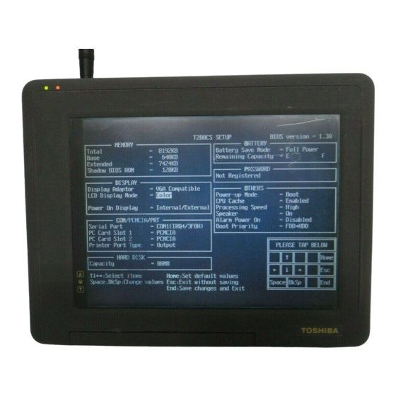
3.24.2 Accessing the SETUP Program Select 0 from the DIAGNOSTICS MENU and tap or press Enter to display the following: T200 SETUP BIOS version = x.xx BATTERY MEMORY Battery Save Mode = Full Power Total = 4096 KB Remaining Capacity... -
Page 103: Setup Options
This field displays the amount of extended memory available. These values may not be changed by the user. Shadow BIOS ROM The SETUP program displays 128 KB of RAM reserved for Shadow BIOS ROM. These values may not be changed by the user. 3-53 T200, T200CS... - Page 104 LCD Gray Scale Level (T200 only) Use this option, which appears in SETUP, to switch between normal and reverse video on the T200. It does not appear on the T200CS. The options are: Normal 16 levels Displays black text on a white background with 16 shades of gray.
- Page 105 Choose this selection when a PCMCIA card is installed. (This isthe default.) Others Choose this selection when a Toshiba card modem is installed. NOTE: Only one PC Card Slot can be set to Others. For example, if PC Card Slot 1 is set to Others and you also set PC Card Slot 2 to Others, PC Card Slot 1 automatically changes to PCMCIA.
- Page 106 Choose this selection when a PCMCIA card is installed. (This isthe default.) Others Choose this selection when a Toshiba card modem is installed. When Others is chosen, use the sub-window shown below to control the modem COM Port and power.
- Page 107 This option is used to select Full Power, Low Power, or User Setting of the BATTERY SAVE OPTION. Full Power The following shows full power settings. CPU Sleep Mode Disabled Display Auto Off = Disabled (T200) 30 Min.(T200CS) HDD Auto Off Disabled System Auto Off Disabled LCD Brightness...
- Page 108 Enables the CPU cache. (This is the default.) Disabled Disables CPU cache. Processing Speed This feature changes the CPU processing speed. High The CPU operates at 40 MHz. (This is the default.) The CPU operates at half-speed. 3-58 T200, T200CS...
- Page 109 The computer looks for bootable files first on the HDD, then on the FDD. (This is the default.) Battery Save Options CPU Sleep Mode Use this option to enable or disable the CPU sleep function. Enabled Enables sleep mode. Disabled Disables sleep mode. 3-59 T200, T200CS...
- Page 110 1, 3, 5, 10, 15, 20 or 30 minutes. Always OFF Turns off the power to the LCD panel illumination. This option appears only on the T200. HDD Auto Off Use this option to disable or set the duration of the HDD automatic power- off function.
-
Page 111: Before You Begin
You will remove and replace many screws when you disassemble the computer. When you remove screws, make sure they are placed in a safe place and identified with the correct parts. T200, T200CS... -
Page 112: Disassembly Procedures
Make sure the correct screws are used to secure all FRUs. Using the wrong screw can either damage the threads or the screw head, and may prevent proper seating of an FRU. After installing an FRU in the computer confirm that the FRU and the computer are function- ing properly. T200, T200CS... -
Page 113: Tools And Equipment
Tweezers, to lift out screws that you cannot grasp with your fingers. ESD mats for the floor and the table you are working on. An ESD wrist strap or heel grounder. Anti-static carpeting or flooring. Air ionizers in highly static sensitive areas. T200, T200CS... -
Page 114: Removing The Battery Pack
To clear the second latch, insert your fingers in the gap between the computer and the battery pack and push carefully with one hand until the battery pack is free (Figure 4-1). Firmly grasp the battery pack and pull it out (Figure 4-1). Figure 4-1 Removing the Battery Pack T200, T200CS... -
Page 115: Installing The Battery Pack
NOTE: The battery pack is designed to fit into the computer in only one way. To install the computer’s battery pack, follow the steps below and refer to Figure 4-1: Gently slide the battery pack into the battery slot . Push the battery pack in until it locks into place (Figure 4-1). T200, T200CS... -
Page 116: Removing The Optional Memory Card
Grasp the card and pull it out of the computer (Figure 4-2). Figure 4-2 Removing the Optional Memory Card CAUTION: DO NOT touch the connecting edge of the memory card. Debris or oil in or on the connector may cause memory access problems. T200, T200CS... -
Page 117: Installing The Optional Memory Card
(arrow first) into the slot. Push gently to ensure a firm connection (Figure 4-2). Close the expansion slot cover. Install the battery pack as described in section 4.2. The computer automatically configures all additional memory. T200, T200CS... - Page 118 Grasp the card and pull it out of the computer (Figure 4-3). Figure 4-3 Removing the Optional PCMCIA Card CAUTION: DO NOT touch the connecting edge of the PCMCIA card. Debris or oil in or on the connector may cause access problems. T200, T200CS...
- Page 119 When the card is almost fully seated, you will feel some resistance. Press gently until the eject button pops out. Do not force the card into position. Close the expansion card cover. Install the battery pack as described in section 4.2. T200, T200CS...
-
Page 120: Removing The Hard Disk Drive
NOTE: The HDD cover is held in place by one screw and two latches. Be careful to rotate the cover out as indicated in Figure 4-4 when removing it , and engage the latches first, then rotate it into place when seating it. 4-10 T200, T200CS... - Page 121 Carefully rotate the HDD cover out of its seating and gently disconnect the RTC battery from the HDD cover (Figure 4-5). Figure 4-5 Disconnecting the RTC Battery Lift up and pull on the HDD handle to disconnect the HDD connector (Figure 4-6). Figure 4-6 Removing the HDD with Bracket 4-11 T200, T200CS...
- Page 122 Remove the four flat-head M1.6x4 silver screws securing the bracket to the HDD and slip off the bracket (Figure 4-7). Figure 4-7 Removing the HDD 4-12 T200, T200CS...
-
Page 123: Installing The Hard Disk Drive
Connect the RTC battery to the HDD cover (Figure 4-5). Replace the HDD cover and secure it with the one M2.5x6 screw (Figure 4-4). Install the optional PCMCIA card, optional memory card, and battery pack as described in sections 4.2, 4.3 and 4.4. 4-13 T200, T200CS... -
Page 124: Removing The Back Cover
3. When removing the cover, you will need to press in the eject button of the optional PCMCIA card 2. Pull the cover to release the seven latches connecting it to the computer (Figure 4-8). Figure 4-8 Removing the Back Cover 4-14 T200, T200CS... - Page 125 Install the HDD, optional PCMCIA card, optional memory card, and battery pack as described in sections 4.2, 4.3, 4.4, and 4.5. NOTE: When installing the cover, you will need to press in the eject button of the optional PCMCIA card 2. 4-15 T200, T200CS...
- Page 126 Reflect the insulator away, then disconnect the RTC battery cable from PJ403, and lift out the RTC battery (Figure 4-9). Disconnect the battery release switch cable from PJ10 (Figure 4-9). Figure 4-9 Removing the Backup Battery and RTC Battery 4-16 T200, T200CS...
- Page 127 Remove the six brass M2.5x4 screws securing the upper system board (Figure 4- 10). Carefully rotate the upper system board out of its seating and disconnect the FL in- verter board cable from PJ204 (Figure 4-10). Figure 4-10 Removing the Upper System Board 4-17 T200, T200CS...
- Page 128 Connect the backup battery cable to PJ203 (Figure 4-9) and replace the protective tape. Connect the battery release switch cable to PJ10 (Figure 4-9). Install the back cover, HDD, optional PCMCIA card, optional memory card, and battery pack as described in sections 4.2, 4.3, 4.4, 4.5 and 4.6. 4-18 T200, T200CS...
- Page 129 T200 Lower System Board Removing the T200 Lower System Board To remove the T200’s lower system board, follow the steps below and refer to Figures 4-12 and 4-13. Turn off the power to the computer. Disconnect the AC adapter, power cord and all external cables connected to the computer.
- Page 130 Carefully rotate the lower system board out of its seating and disconnect the tablet cable from PJ407 and the display cable from PJ404 (Figure 4-13). Figure 4-13 Disconnecting the Tablet Cable and Display Cable 4-20 T200, T200CS...
- Page 131 Installing the T200 Lower System Board To install the T200’s lower system board, follow the steps below and refer to Figures 4-12 and 4- Connect the tablet cable to PJ407 (Figure 4-13). Connect the display cable to PJ404 and carefully rotate the system board (Figure 4- 13).
- Page 132 Remove the black insulator, then disconnect the display cable from PJ405 (Figure 4- 14). Peel back the white tape, then remove the three M2.5x4 screws securing the lower system board (Figure 4-14). Figure 4-14 Removing the T200CS Lower System Board 4-22 T200, T200CS...
- Page 133 Carefully rotate the lower system board out of its seating and disconnect the tablet cable from PJ407 (Figure 4-15). Figure 4-15 Disconnecting the Tablet Cable 4-23 T200, T200CS...
- Page 134 Secure the three M2.5x4 screws on the lower system board (Figure 4-14). Install the upper system board, backup battery, RTC battery, back cover, HDD, optional PCMCIA card, optional memory card, and battery pack as described in sections 4.2, 4.3, 4.4, 4.5 4.6 and 4.7. 4-24 T200, T200CS...
-
Page 135: Fl Inverter Board
Remove the tape and disconnect the FL inverter cable from CN1 and the FL cable from CN2 (Figure 4-16). Remove the three M2.5x4 screws securing the FL inverter board and lift out the FL inverter board (Figure 4-16). Figure 4-16 Removing the FL Inverter Board 4-25 T200, T200CS... -
Page 136: Installing The Fl Inverter Board
Installing the FL inverter Board To install the computer’s FL inverter board, follow the steps below and refer to Figure 4-16. NOTE: The T200 and T200 CS FL inverter boards are different. Check the part number before installing the new FL inverter board. - Page 137 Note the position of the battery push spring, then unsnap the four latches securing the middle frame to the display module, and carefully lift off the middle frame (Figure 4- 17). Figure 4-17 Removing the T200 Base Frame 4-27 T200, T200CS...
- Page 138 Remove the tablet cover (Figure 4-18). Figure 4-18 Removing the T200 Tablet Cover Remove the tablet (Figure 4-19) Figure 4-19 Removing the T200 Tablet 4-28 T200, T200CS...
- Page 139 Installing the T200 Tablet To install the computer’s tablet, follow the steps below and refer to Figures 4-17 through 4-19. Place the tablet on the LCD panel (Figure 4-19), and tablet cover on the tablet (Figure 4-18). When you seat the tablet, align the holes at each corner with the corre- sponding posts on the LCD module.
- Page 140 Note the position of the battery push spring, then unsnap the four latches securing the middle frame to the display module and carefully lift off the middle frame (Figure 4- 20). Figure 4-20 Removing the T200CS Base Frame 4-30 T200, T200CS...
- Page 141 Lift up the display cable and lift the tablet cover out of the display module (Figure 4- 21). Figure 4-21 Removing the T200CS Tablet Cover Lift the tablet off the two guide posts and remove it (Figure 4-22). Figure 4-22 Removing the T200CS Tablet 4-31 T200, T200CS...
- Page 142 Install the FL inverter board, lower system board, upper system board, backup battery, RTC battery, back cover, HDD, optional PCMCIA card, optional memory card, and battery pack as described in sections 4.2, 4.3, 4.4, 4.5, 4.6, 4.7, 4.8, 4.9 and 4.10. 4-32 T200, T200CS...
- Page 143 4.13 T200 Display Module Removing the T200 Display Module To remove the T200's display module, follow the steps below and refer to Figure 4-23. Turn off the power to the computer. Disconnect the AC adapter, and all external cables connected to the computer.
- Page 144 Install the tablet, FL inverter board, lower system board, upper system board, backup battery, RTC battery, back cover, HDD, optional PCMCIA card, optional memory card, and battery pack as described in sections 4.2, 4.3, 4.4, 4.5, 4.6, 4.7, 4.8, 4.9, 4.10 and 4.11. 4-34 T200, T200CS...
- Page 145 4.15 T200 FL Removing the T200 FL To remove the T200's FL, follow the steps below and refer to Figure 4-24. Turn off the power to the computer. Disconnect the AC adapter, and all external cables connected to the computer.
- Page 146 Remove the four M2.5x4 screws securing the FL unit and LCD panel to the LCD cover (Figure 4-25). Figure 4-25 Removing the Four Screws Remove the six M2x2 flat screws securing the FL unit cover (Figure 4-26). Figure 4-26 Removing the FL Unit Cover 4-36 T200, T200CS...
- Page 147 Install the tablet, FL inverter board, lower system board, upper system board, backup battery, RTC battery, back cover, HDD, optional PCMCIA card, optional memory card, and battery pack as described in sections 4.2 through 4.10, and 4.12. 4-37 T200, T200CS...
- Page 148 Remove the tip and pull it out. Use the tweezers. Figure 4-28 Removing the Tip Installing the Tip To install the stylus’s tip, follow the step below and refer to Figure 4-28. Insert the new tip and push gently to fully seat it. 4-38 T200, T200CS...
-
Page 149: Appendix A Handling The Lcd Module
Carefully align the holes at the four corners of the LCD module with correspond- ing holes in the cover before securing with screws. Do not force the module into place, stress can affect its performance. The polarized surface of the panel scars easily, handle carefully. T200/T200CS... - Page 150 Water or other liquids left on the surface for a long period can change the screen tint or stain the screen. Be sure to quickly wipe off any liquid. Do drop or strike the LCD module with a hard object, glass used in the panel could break or crack. T200/T200CS...
- Page 151 CMOS-LSI circuits. Do not expose the module to direct sunlight or strong ultraviolet rays for long periods. Do not store the module at temperatures below specifications. Cold can cause liquid crystals to freeze, lose their elasticity, or otherwise suffer damage. T200/T200CS...
- Page 152 If transporting the module, do not use packing materials that contain epoxy resin (amine) or silicon glue (alcohol or oxime). These materials can release gas that can damage panel polarization. T200/T200CS...
-
Page 153: Appendix B Board Layout
Appendix B Board Layout Upper System Board (FOGSD2) Figure B-1 Upper System Board FOGSD2 (Front) T200/T200CS... - Page 154 Figure B-2 Upper System Board FOGSD2 (Back) T200/T200CS...
- Page 155 Table B-2 Upper ICs and Connectors on the System Board (Back) Mark Number Name CPU 486DX2 System controller gate array Clock generator Super integration (T9901) BIOS ROM IC19 PCMCIA controller gate array PJ10 Battery release switch connector PJ203 Backup battery connector T200/T200CS...
- Page 156 Lower System Board (FOGSU2) Figure B-3 Lower System Board FOGSU2 (Front) T200/T200CS...
- Page 157 Figure B-4 Lower System Board FOGSU2 (Back) T200/T200CS...
- Page 158 PJ401 Joint connector PJ403 RTC battery connector PJ405 T200CS display connector PJ408 HDD connector Table B-4 Lower ICs and Connectors on the System Board (Back) Mark Number Name PJ402 Memory card connector PJ404 T200 display connector PJ407 Tablet connector T200/T200CS...
-
Page 159: Appendix C Pin Assignments
– D03;110 SD00;100 D04;110 SD01;100 D05;110 SD02;100 D06;110 SD03;100 D07;110 SD04;100 D08;110 SD05;100 D09;110 SD06;100 D10;110 SD07;100 D11;110 SD08;100 D12;110 SD09;100 D13;110 SD10;100 D14;110 SD11;100 D15;110 SD12;100 D16;110 SD13;100 D17;110 SD14;100 D18;110 SD15;100 D19;110 SA00;100 – SA01;100 D20;110 SA02;100 T200/T200CS... - Page 160 – CTS2;000 FLTEN;000 – PNEL0;100 RTCSBY;000 CNTBEN;000 RTCWR;000 CNTRST;000 RTCAS;100 TF0;100 RTCDS;000 TF1;100 IRQ8;000 TF2;100 C32KHZ;000 TLCH;100 – – LD0;110 – LD1;110 – LD2;110 – LD3;110 – UD0;110 – UD1;110 – UD2;110 – UD3;110 – CDU0;110 – CDU1;110 – T200/T200CS...
- Page 161 Table C-3 FDD Connector Pin Assignment (26-Pin) Signal Signal FVCC201 – IFSTEP;010 IFINOX;000 – FVCC201 – IFWDAT;010 FVCC201 – FVCC201 – IFWEN;010 DSKCHG;000 – IFDASL;010 – IFTRKO;000 IFRADY;000 – IFHMED;000 IFWPRD;000 IFAMON;010 – IFLOD1;010 IFRDAT;000 IFDIRC;010 – IFLOD2;010 IFSSEL;010 T200/T200CS...
- Page 162 Table C-5 PS/2 Keyboard Connector Pin Assignment (6-Pin) Signal Signal EKBDAT — — EKBCLK — — PJ6 External Display Connector (15-Pin) Table C-6 External Display Connector Pin Assignment (15-Pin) Signal Signal ARED;110 — AGREEN;110 — ABLUE;110 — — — — CHSYNC;120 — CVSYNC;120 — — — T200/T200CS...
- Page 163 DCINP DCINP DCINP DCINP DCINP DCINP – RXD1;010 TXD1;010 DTR1;110 RI1;110 DCD1;110 MOUSDT;100 – – RKBDAT;100 PRCHEK;000 IFWEN;000 IHMED;000 IFRADY;010 IFDIRC;000 IFINDX;010 IFSSEL;000 SELCT;110 IFTRK0;010 SLIN;000 BUSY;110 – PD7;100 PD2;100 PD4;100 PD0;100 – STROB;000 – – CHSYNC;120 – – T200/T200CS...
- Page 164 — MCVCCA — MCVPP1A — MCVPP2A — CAD16A;100 CAD22A;100 CAD15A;100 CAD23A;100 CAD12A;100 CAD24A;100 CAD07A;100 CAD25A;100 CAD06A;100 — CAD05A;100 CRSETA;100 CAD04A;100 WAITA;000 CAD03A;100 INPCKA;000 CAD02A;100 REGA;000 CAD01A;100 BVD2A;100 CAD00A;100 BVD1A;100 PCD00A;100 PCD08A;100 PCD01A;100 PCD09A;100 PCD02A;100 PCD10A;100 WPA;000 CD2A;000 — — T200/T200CS...
- Page 165 — MCVCCB — MCVPP1B — MCVPP2B — CAD16B;100 CAD22B;100 CAD15B;100 CAD23B;100 CAD12B;100 CAD24B;100 CAD07B;100 CAD25B;100 CAD06B;100 — CAD05B;100 CRSETB;100 CAD04B;100 WAITB;000 CAD03B;100 INPCKB;000 CAD02B;100 REGB;000 CAD01B;100 BVD2B;100 CAD00B;100 BVD1B;100 PCD00B;100 PCD08B;100 PCD01B;100 PCD09B;100 PCD02B;100 PCD10B;100 WPB;000 CD2B;000 — — T200/T200CS...
- Page 166 PJ203 Backup Battery Connector (2-Pin) Table C-13 Backup Battery Connector Pin Assignment (2-Pin) Signal Signal SUBBAT – – C.14 PJ204 FL Inverter Connector (6-Pin) Table C-14 FL Inverter Connector Pin Assignment (6-Pin) Signal Signal – BRTNH – – FLON – T200/T200CS...
- Page 167 RAS0 CAS2 CAS0 — CAS1 CAS3 VCC3 — RAS3 RAS2 — VCC5 — — D017 — VCC3 — D035 — D010 D027 VCC5 — D028 D011 D029 D012 D030 D013 D031 D014 D032 D015 D033 D016 D034 — — T200/T200CS...
- Page 168 PJ403 RTC Battery Connector (3-Pin) Table C-16 RTC Battery Connector Pin Assignment (3-Pin) Signal Signal RTCBAT – – – C.17 PJ404 T200 Display Connector (23-Pin) Table C-17 T200 Display Connector Pin Assignment (23-Pin) Signal Signal – – – DOFF – – C.18...
- Page 169 RESET;000 – – IOCRDY;100 HSD07;100 – HSD08;100 – HSD06;100 – HSD09;100 IRQ14;100 HSD05;100 IOCS16;000 HSD10;100 SA01;100 HSD04;100 – HSD11;100 SA00;100 HSD03;100 SA02;100 HSD12;100 HDC0CS;000 HSD02;100 HDC1CS;000 HSD13;100 – HSD01;100 – HSD14;100 – HSD00;100 – HSD15;100 – – – C-11 T200/T200CS...
- Page 170 Appendix D USA Display Codes Table D-1 USA Display Codes T200/T200CS...
-
Page 171: Keyboard Scan/Character Codes
Appendix E Keyboard Scan/Character Codes Table E-1 Scan Codes (Set 1 and Set 2) (1/3) Code set 1 Code set 2 Keytop Make Break Make Break Note ‘ ~ 7 & BkSp 29 (42) Caps Lock T200, T200CS... - Page 172 E0 F0 11 E0 F0 70 E0 F0 71 ← E0 F0 6B Home E0 F0 6C E0 F0 69 ↑ E0 F0 75 ↓ E0 F0 72 PgUp E0 F0 7D PgDn E0 F0 7A → E0 F0 74 T200, T200CS...
- Page 173 4* Fn key does not generate a code by itself. 5* This key corresponds to key No. 42 in 102-key model. 6* Refer to Table E-6, scan codes with Ctrl key. 7* Refer toTable E-7, scan codes with Alt key. T200, T200CS...
- Page 174 PgDn E0 2A E0 51 E0 D1 E0 AA E0 12 E0 7A E0 F0 7A E0 F0 12 → E0 2A E0 4D E0 CD E0 AA E0 12 E0 74 E0 F0 74 E0 F0 12 T200, T200CS...
- Page 175 E0 2A E0 37 E0 B7 E0 AA E0 12 E0 7C E0 F0 7C E0 F0 12 Ctrl* E0 37 E0 B7 E0 7C E0 F0 7C Shift* E0 37 E0 B7 E0 7C E0 F0 7C Alt* F0 B4 T200, T200CS...
- Page 176 Table E-7 Scan Codes with Alt Key Code set 1 Code set 2 Shift Make Make Pause Common SD C5 F0 77 Ctrl* *: This key generates only make codes. T200, T200CS...
-
Page 177: Wiring Diagrams
(4) DTR Figure F-2 RS-232C Wraparound Connector RS-232C Direct Cable (9-Pin to 9-Pin) (3) TD (4) DTR (7) RTS (5) GND (2) RD (1) CD (6) DSR (8) CTS (9) RI Figure F-3 RS-232C Direct Cable (9-pin to 9-pin) T200/T200CS... - Page 178 RS-232C Direct Cable (9-Pin to 25-Pin) (1) CD (2) RD (3) TD (4) DTR (22) (5) GND (7) RTS (6) DSR (20) (8) CTS (9) RI Figure F-4 RS-232C Direct Cable (9-pin to 25-pin) T200/T200CS...
-
Page 179: Appendix G Deleting The Password
Connect the parallel cable to the PRT port. Connect the printer wraparound connector to the parallel cable. Turn on the power to the computer. When the OS is loaded, the password is automati- cally removed. Remove the printer wraparound connector and parallel cable. T200/T200CS... -
Page 180: Appendix Hbios Rewrite Procedures
This Appendix explains how to rewrite the system BIOS program when updating the BIOS on the computer. Tools To rewrite the BIOS, the following tool is required: BIOS rewrite disk for the T200/T200CS Rewriting the BIOS Follow the procedures below to perform the BIOS rewrite program. Set the system to Boot Mode.
Need help?
Do you have a question about the T200 and is the answer not in the manual?
Questions and answers