Table of Contents
Advertisement
Advertisement
Table of Contents

Related Manuals for Teletek electronics CA60Plus


Summary of Contents for Teletek electronics CA60Plus
- Page 1 TeleTek CA60Plus Software version 3.1 Installation Manual May 2000...
-
Page 2: Table Of Contents
CA60Plus Installation Manual TeleTek CONTENTS PART I. CA60Plus Security Control Panel Installation..............3 1. Security Control Panel......................4 2. LED Display Keypad......................4 3. Inputs and Outputs.........................5 4. LED Keypad Wiring.......................6 5. Programmable Outputs PGM1, PGM2 and PGM3...............7 6. Programmable Output SIREN....................7 7. -
Page 3: Part I. Ca60Plus Security Control Panel Installation
TeleTek PART I. CA60Plus Security Control Panel Installation The CA60Plus Security Control Panel is designed and tested in accordance with the EMC standards. For the reliable functioning of the system, please have in mind the following recommendations: Make sure that the control panel is well earthened. -
Page 4: Security Control Panel
F - 0,63 A Transmitter BATTERY 1 - Mounting holes Powering 12V / 7 Ah 2 - CA60Plus Security Panel Transformer 3 - AC terminal 50 / 60 Hz 4 - Signal cables holes 17 V / 24VA 5 - AC cable hole Fig.1 CA60Plus Security Control Panel... -
Page 5: Inputs And Outputs
CA60Plus Installation Manual TeleTek 3. Inputs and Outputs Reset jumper F1 (BATT) - 2 A F2 ( AUX) - 1 A F3 (PGM) - 1 A BATTERY 12 V / 7 Ah Fig. 3 Inputs and Outputs • • • • • AC - 17 V/24 VA AC transformer power supply •... -
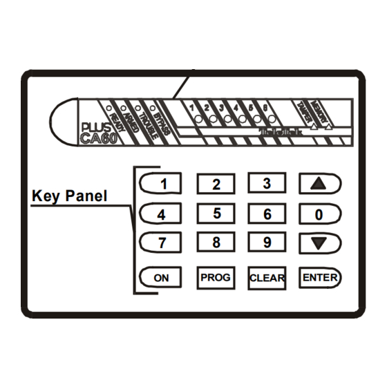
Page 6: Led Keypad Wiring
Fig. 4Keypad - Panel Connecting The CA60Plus control panel keypad is wired by the manufacturer with a 20 cm long cable bundle. While connecting the bundle to the panel have in mind the colour match of the different wires (See Fig.4). -
Page 7: Programmable Outputs Pgm1, Pgm2 And Pgm3
CA60Plus Instalation Manual TeleTek 5. Programmable Outputs PGM1, PGM2 and PGM3 The PGM1, PGM2 and PGM3 security panel outputs have a programmable active level. Thus they could be used for generating managing signals to exterior units (for example a siren with a blocking input) or direct managing of low power exterior units (such as relays, LEDs, etc.). - Page 8 CA60Plus Installation Manual TeleTek On Fig. 8 is described the SR2000 siren (produced by TeleTek ) wiring. Two managing signals are ® used - SIREN and PGM3. When an alarm event occurs the SIREN output switches to a low level and activates the SR2000 siren.
-
Page 9: Detectors Wiring
CA60Plus Installation Manual TeleTek 7. Detectors Wiring The CA60 Plus control panel operates with dry relay contacts detectors. It is also possible fire detectors with a relay output to be used. To balance the zones use the applied 1 kΩ resistors. The balancing resistors should be housed in the last detector in the chain. -
Page 10: Internal Communicator Wiring
TeleTek 8. Internal Communicator Wiring The telephone line is connected to A and B terminals of the CA60Plus security panel regardless the polarity (See Fig. 10). The phone is connected to A1 and B1 terminals of the CA60Plus security panel regardless the polarity (See Fig. -
Page 11: Part Ii. Programming The Ca60Plus Parameters
B. Programming the CA60Plus using Remote Programming software “Up/Down Load” After installing there is a posibility to program control panel CA60Plus using Remote Programming software in time period of 24 hours after RESET. The connection will be with DEFAULT configuration of Up/Down Load parameters (addresses 54, 55, 56, 57, 58 and 59). - Page 12 Arming PART 1 User Code 3 Rights Arming PART 2 Event Memory Review User Code 4 Rights Zone Bypass User Code 5 Rights User Code 6 Rights Master Code Access to Enabled/Disabled the User Codes Rights Fig. 11 CA60Plus Parameters Programming...
- Page 13 Test Modes Walk Test End of Communication and Led Test Non-transmitted Events Erasure Output Test Communicator Test Display Log Previous Event Remote Programming Next Event Display End of Remote programming CLEAR ENGINEER MENU Exit Fig. 11 CA60Plus Parameters Programming - continue...
-
Page 14: Zone Configuration
CA60Plus Installation Manual TeleTek 1. Zone Configuration ADDRESS 10 ZONE BALANCING TYPE In this address the zone balancing type is set. Each pressing of a digit key alters the balancing type. The display indication is described in the table. One balancing resistor. The LEDs from 1 to 6 light. - Page 15 CA60Plus Installation Manual TeleTek ADDRESS 15 ZONE 5 - TYPE AND ATTRIBUTES Programming as in address 11. DEFAULT : PANIC type ADDRESS 16 ZONE 6 - TYPE AND ATTRIBUTES Programming as in address 11. DEFAULT : TAMPER type The zone types options and attributes are listed in Table 1 Table 1.
- Page 16 CA60Plus Installation Manual TeleTek When this zone type is activated, the MEDICAL type programmed outputs and MEDICAL the communicator are activated. Regardless the status of the system, the LED of the activated zone lights. The memory is erased either by reentering a valid user code or when the system is armed.
-
Page 17: Pgm And Siren Programmable Outputs Configuration
CA60Plus Installation Manual TeleTek 2. PGM AND SIREN PROGRAMMABLE OUTPUTS CONFIGURATION ADDRESS 21 PGM1 PROGRAMMABLE OUTPUT In this address the events which will force the programmable output to move into an active level are programmed. A free combination of events activating the programmable output is allowed. - Page 18 CA60Plus Installation Manual TeleTek ADDRESS 22 PGM2 PROGRAMMABLE OUTPUT Programming as in address 21. DEFAULT : ALARM, TAMPER, POL “+” ADDRESS 23 PGM3 PROGRAMMABLE OUTPUT Programming as in address 21. DEFAULT : AC LOSS, BAT LOW, FUSE, POL “+” ADDRESS 24 SIREN PROGRAMMABLE OUTPUT The SIREN output is activated by 4 events.
-
Page 19: Times
CA60Plus Installation Manual TeleTek 3. TIMES ADDRESS 30 EXIT TIME PROGRAMMING The EXIT TIME for the ENTRY/EXIT type zones is set in this address. The EXIT TIME number of seconds from 01 to 60 is entered. For a time period less than 10 sec the first digit should be 0. -
Page 20: Code System Management
CA60Plus Installation Manual TeleTek 4. CODE SYSTEM MANAGEMENT ADDRESS 40 SET WITH CODE Full or Partial arming of the area does not require confirmation by entering a valid user code. The LEDs from 1 to 6 do not light. Full or Partial arming of the area requires confirmation by entering a valid user code. -
Page 21: Engineer Parameters
CA60Plus Installation Manual TeleTek 5. ENGINEER PARAMETERS ADDRESS 50 ENGINEER CODE CHANGE In this address a new access code to the engineer parameters of the control panel is set. On the keypad display the LEDs: 3, 4, 5 and 6 light. After each entering of a digit of the new code, one LED stops lighting. - Page 22 CA60Plus Installation Manual TeleTek ADDRESS 57 CALL BACK OPTION In this address the Call Back option for remote programming is set. Each pressing of a digit key alters the Call Back option enable / disable. If Call Back option enabled, after an incoming call and request for remote programming, control panel hangs up and dials the number of remote PC.
-
Page 23: Communicator Parameters
CA60Plus Installation Manual TeleTek 6. COMMUNICATOR PARAMETERS Before configuring the communicator call your Monitoring company and specify the necessary parameters - phone numbers, the subscriber account number, communication report and event codes. Before starting to configure the parameters erase the non-transmitted codes from the event buffer in address 93 by pressing the 0 key once. - Page 24 CA60Plus Installation Manual TeleTek ADDRESS 65 SUBSCRIBER ACCOUNT NUMBER 2 This is the panel ID number for the secondary monitoring station. The lenght of PANEL ID 2 the number is 3 or 4 digits (depending on the report format - 3x or 4x). The 0...
-
Page 25: Communicator Test Parameters
CA60Plus Installation Manual TeleTek 7. COMMUNICATOR TEST PARAMETERS ADDRESS 70 SYSTEM CLOCK SETTINGS In this address the hour and minutes are set (HH:MM). The indication is CLOCK hexadecimal and the digits show up one by one. The digits are monitored by the arrow keys. -
Page 26: Communicator Event Codes
CA60Plus Installation Manual TeleTek 8. COMMUNICATOR EVENT CODES For the Report Codes only the first symbol should be entered. The second is automatically generated by the security panel. If the symbol 0 is entered as a code, the respective event will not be transmitted by the communicator. - Page 27 CA60Plus Installation Manual TeleTek ADDRESS 86 ARM REPORT CODE Arm Report code (X). Hexadecimal indication. The code number is added ARM CODE automatically before transmitting the message to the monitoring station. DEFAULT : 7 ADDRESS 87 DISARM REPORT CODE Disarming Report code (X). Hexadecimal indication. The code number is added DISARM CODE automatically before transmitting the message to the monitoring station.
-
Page 28: Ca60Plus Test Modes
CA60Plus Installation Manual TeleTek 9. CA60Plus TEST MODES ADDRESS 90 WALK TEST Allows functional zone test. Under this mode the respective activated zone WALK TEST LED flashes. If an open tamper is present the respective zone LED illuminates constantly. ADDRESS 91 KEYPAD TEST Tests the reliability of the LEDs and the keypad buzzer. -
Page 29: Reset Parameters Table
CA60Plus Installation Manual TeleTek APPENDIX A RESET Parameters Table PROGRAM MENU ADDRESS LED 1 LED 2 LED 3 LED 4 LED 5 LED 6 LOOP TYPE DUAL - LED1 to LED6 do not light ALARM - LED1 to LED6 light... - Page 30 CA60Plus Installation Manual TeleTek PROGRAM MENU ADDRESS LED 1 LED 2 LED 3 LED 4 LED 5 LED 6 CLOCK Clock Settings ( HH:MM) TEST TIME Test peport time ( HH:MM) TEST PERIOD Auto reporting(DD) TEST CODE TEST code. RESET A value.
- Page 31 CA60Plus Installation Manual TeleTek Programming by the Master User MANAGER MENU ADDRESS LED 1 LED 2 LED 3 LED 4 LED 5 LED 6 CHNG OWN CODE DIGIT 1 DIGIT 2 DIGIT 3 DIGIT 4 CHANGE USER 1 DIGIT 1...
- Page 32 WARRANTY Warranty conditions for the CA60 plus may vary from country to country. Please consult your local dealer for complete waranty information. In all cases, the warranty does not cover malfunc- tions arising from installer error or failure to follow installation/operation instructions, nor does it aplly to damages due to causes beyond the control of TeleTek Ltd., such as lighting, excessive voltage, mechanical shock or water damage.
Need help?
Do you have a question about the CA60Plus and is the answer not in the manual?
Questions and answers