Teletek electronics ECLIPSE 8 Installation Manual
Alarm control panel
Hide thumbs
Also See for ECLIPSE 8:
- User's operation manual (48 pages) ,
- Installation manual (28 pages) ,
- Engineer programming manual (96 pages)
Table of Contents
Advertisement
Quick Links
INSTALLATION
MANUAL
ECLIPSE 8
ECLIPSE 16
ECLIPSE 32
ECLIPSE 99
(S.W. 3.xx)
ALARM CONTROL PANELS
Attention:
This manual contains information on limitations regarding product use and
function and information on the limitations as to liability of the manufacturer.
The entire manual should be carefully read.
The information in this manual is a subject to change without notice!
Advertisement
Table of Contents

Related Manuals for Teletek electronics ECLIPSE 8


Summary of Contents for Teletek electronics ECLIPSE 8
- Page 1 INSTALLATION MANUAL ECLIPSE 8 ECLIPSE 16 ECLIPSE 32 ECLIPSE 99 (S.W. 3.xx) ALARM CONTROL PANELS Attention: This manual contains information on limitations regarding product use and function and information on the limitations as to liability of the manufacturer. The entire manual should be carefully read.
-
Page 2: Table Of Contents
Eclipse 8/16/32/99 Series - Installation Manual Table of Contents: QUICK STEPS OF INSTALLATION ..........................4 1. GENERAL INFORMATION ............................6 2. INSTALLATION ................................7 2.1. Control Panels Mounting ..........................7 2.1.1 ECLIPSE 8/16 ..........................7 2.1.2 ECLIPSE 32/99 ..........................8 2.2. - Page 3 The manufacturer shall not accept any product, of which no prior notice has been received via the RAN form at: http://www.teletek- electronics.com/en/support/Service The setup and programming included in the technical documentation shall not be regarded as defects. Teletek Electronics bears no responsibility for the loss of programming information in the device being serviced. CONDITIONS FOR WAIVING THE GUARANTEE This guarantee shall apply to defects in products resulting only from improper materials or workmanship, related to its normal use.
-
Page 4: Quick Steps Of Installation
Connect the detectors in the zones as use one of the following connection diagrams according the respective application. According your system you can choose among different connection styles diagrams: ECLIPSE 8 - 5 connection styles diagrams for single zone connection ECLIPSE 16 - 5 connection styles diagrams for single zone connection... - Page 5 3. Program the parameters of the PGM outputs, time slots, areas and users in the system – for details see the Programming tables in the ECLIPSE 8/16/32/99 Series - Engineer Programming Manual. Note: If the PGM5 (ECLIPSE 32 or ECLIPSE 99) output is not used for connecting siren you must program it as PGM with general application.
-
Page 6: General Information
Eclipse 8/16/32/99 Series - Installation Manual 1. GENERAL INFORMATION The ECLIPSE series Alarm control panels are designed and tested in compliance with electromagnetic compatibility (EMC) standards. The following recommendations need to be observed for the proper performance of the alarm station: ➢... -
Page 7: Installation
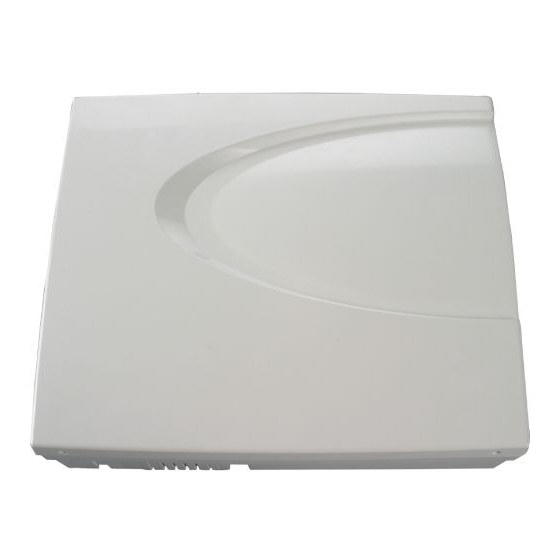
2.1.1 ECLIPSE 8/16 ECLIPSE 8/16 Alarm Control Panel is mounted in a white plastic box with dimensions 290 x 240 x 80mm. There is additional space for mounting of one communication module in the box. For the back-up battery is provided special place. -
Page 8: Eclipse 32/99
Eclipse 8/16/32/99 Series - Installation Manual 2.1.2 ECLIPSE 32/99 ECLIPSE 32/99 Alarm Control Panel is mounted in a white plastic box with dimensions 335 x 290 x 105mm. There are additional spaces for mounting of one communication module in the box and one expander module (under the main PCB). -
Page 9: Control Panels Pcb Layouts
Eclipse 8/16/32/99 Series - Installation Manual 2.2. Control Panels PCB Layouts 2.2.1 ECLIPSE 8 Figure 5. ECLIPSE 8 control panel ECLIPSE 8 - Terminals and components: 17VAC – Power supply from a mains transformer 17V/17VA, fuse 0.63А – Grounding +/- AUX – Power supply for detectors with consumption up to 0.5А... -
Page 10: Eclipse 16
Eclipse 8/16/32/99 Series - Installation Manual 2.2.2 ECLIPSE 16 Figure 6. ECLIPSE 16 control panel ECLIPSE 16 - Terminals and components: 17VAC – Power supply from a mains transformer 17V/23VA, fuse 0.63А – Grounding +/- AUX – Power supply for detectors with consumption up to 0.5А... -
Page 11: Eclipse 32
Eclipse 8/16/32/99 Series - Installation Manual 2.2.3 ECLIPSE 32 Figure 7. ECLIPSE 32 control panel ECLIPSE 32 - Terminals and components: 21VAC – Power supply from a mains transformer 21V/50VA, fuse 0.63А – Grounding +/- AUX – Power supply for detectors with consumption up to 0.75А... -
Page 12: Eclipse 99
Eclipse 8/16/32/99 Series - Installation Manual 2.2.4 ECLIPSE 99 Figure 8. ECLIPSE 99 control panel ECLIPSE 99 - Terminals and components: 21VAC – Power supply from a mains transformer 21V/50VA, fuse 0.63А – Grounding +/- AUX – Power supply for detectors with consumption up to 0.75А... -
Page 13: Zone Connection
Menu 4. INPUTS (ADDRESS 2000 or OPERATION 200) and it is common for all zones in the system. ATTENTION: ECLIPSE 8/16 Control panels support only single connection in the zones. ECLIPSE 32/99 Control panel supports both single and doubling connection in the zones. - Page 14 Eclipse 8/16/32/99 Series - Installation Manual Examples for realizing different connection styles using TITAN series detectors. NOTE: The connection style 3. NO with EOL is applicable only for detectors with normal open (NO) type terminals. 4. NC without EOL, TAMPER 1.
-
Page 15: Connecting Shutter Detector To A Zone (For Eclipse 16/32/99)
Eclipse 8/16/32/99 Series - Installation Manual 2.3.2 Connecting shutter detector to a zone (for ECLIPSE 16/32/99) The hardware implementation of Zone with set attribute “Pulse count” permits performance in pulse count mode, suitable for connecting a rolling shutters detector. This mode counts short pulses - 2 to 4 ms for a period of 20 seconds. -
Page 16: Connecting Fire Lines
2.3.4 Connecting Fire Lines Fire detectors can be connected to every zone set as Fire type zone. For ECLIPSE 8 and ECLIPSE 16 is possible to realize only 4-wire connection of 12V alarm fire base with one or two balancing resistors. -
Page 17: Connection Of Peripheral Devices
Eclipse 8/16/32/99 Series - Installation Manual 2.4. Connection of Peripheral Devices 2.4.1 Connection to the System Bus ECLIPSE Control Panels Series – DEVICE capability: Max. devices Control panel Keyboards Proxy Zone exp. PGM exp. Wireless exp. on system bus ✓... -
Page 18: Supported Keyboards
Eclipse 8/16/32/99 Series - Installation Manual 2.4.2 Supported Keyboards Summary for ECLIPSE Series Keyboards: Keyboard Display Buttons Areas Zones Proximity card reader 1 x AUX PGM LED 8 Silicone LED 16A Silicone ✓ (option) LED 32 Silicone ✓... - Page 19 Eclipse 8/16/32/99 Series - Installation Manual • Technical Specifications: Feature LED 8 LED 16A LED 32 LCD 32 LCD 32 Sens. GRADE Conformity GRADE 2, Class II* GRADE 3, Class II* Power Supply 9-18V (nom. 14V) Min. 50mA/ Min. 50mA/ Min.
- Page 20 Eclipse 8/16/32/99 Series - Installation Manual settings and moves forward as the current index number is increased with +1. Bypassing zones. The button lights on permanently if there are bypassed zones in the system. The button is blinking during the bypassed zones review.
-
Page 21: Supported Wired Expander Modules
Eclipse 8/16/32/99 Series - Installation Manual 2.4.3 Supported Wired Expander modules Summary for ECLIPSE Series Expander modules: Module Description ECLIPSE 8 ECLIPSE 16 ECLIPSE 32 ECLIPSE 99 ✓ ✓ ✓ ZONE 8 8-Zone expander ✓ ✓ PGM 8 8-PGM expander ... - Page 22 Eclipse 8/16/32/99 Series - Installation Manual • Expanders’ Terminals and Specifications Technical Specifications: GRADE 3 Class II Yes* 11.5 ÷ 18V DC Power Supply from the panel Min. 30mA/ Consumption Max. 100mA Zone inputs PGM output, 100mA, OC type -20°C ÷ 50°C Operation temperature -40°C ÷...
- Page 23 Eclipse 8/16/32/99 Series - Installation Manual Technical Specifications: Main power supply 230VAC +10%/ -15% Transformer 17V/17 VA Backup power supply 12V/7 Ah Consumption Min. 30mA/Max. 750mA Zone inputs PGM outputs -20°C ÷ 50°C Operation temperature -40°C ÷ 60°C Storage temperature Button 17VAC –...
-
Page 24: Supported Wireless Expander Module
Eclipse 8/16/32/99 Series - Installation Manual 2.4.4 Supported Wireless Expander Module Eclipse WL is a wireless expander module designed for building of hybrid alarm systems with Eclipse 16/32/99 control panels and wireless devices BRAVO series. Eclipse WL is mounted in a small plastic box and it is connected to the system bus of the control panel – see connection diagram on Figures 13 and 14. -
Page 25: Supported Proximity Card Readers
Trouble indications. Portable LED or LCD type keyboards can be used to accomplish such tasks. Up to 8/32/64/99 cards can be assigned to one ECLIPSE 8/16/32/99 security systems - one card for each of the users. The Managers in the system are allowed to program the performance of the cards. - Page 26 Eclipse 8/16/32/99 Series - Installation Manual • Installation of proximity reader Eclipse PR Eclipse PR is a stand-alone proximity card reader, which is connected to the system bus of the control panel. The reader is with compact design and is suitable for wall mounting: Technical Specifications: 9 ÷...
-
Page 27: Connection Of Pgm Outputs
Eclipse 8/16/32/99 Series - Installation Manual 2.5. Connection of PGM Outputs ECLIPSE Control Panels Series – PGM capability: Control panel Max. PGM outputs Power output, up to 1A PGM Additional Functionality ECLIPSE 8 1 (PGM 5), non-monitored PGM 4 - Serial link to TP2000 transmitter... - Page 28 In ECLIPSE 8, when set at address 3000, PGM 4 can be used for serial connection to TP2000 transmitter. The serial link is realized with connection between the AC terminal of the transmitter and PGM 4 on the ECLIPSE 8 –...
-
Page 29: Connection Of Siren To Power Pgm Output
2.6. Connection of Siren to Power PGM Output In ECLIPSE 8/16 Alarm panel, the PGM 5 (BELL) output has a programmable active level. The default configuration of PGM5 is with SIREN functionality. The output is activated in case of alarm event in the system. The output is non- monitored. -
Page 30: Connecting The Digital Communicator
2.7. Connecting the Digital Communicator The telephone line is connected to TIP and RING terminals on the ECLIPSE 8/16/32/99 Control Panel with no requirements to observe polarity (see Figures 5-8). The telephone device is connected to TIP1 and RING1 terminals on the ECLIPSE 8/16/32/99 Control Panel with no requirements to observe polarity. -
Page 31: Connecting Communication Modules
The supported communication modules are: - TTE GPRS Standard. Use a serial interface cable to connect the Eclipse 8/16/32/99 panel to the GPRS module. - TTE GPRS Simple. Use a serial interface cable to connect the Eclipse 8/16/32/99 panel to the GPRS module. -
Page 32: Trouble Events
Eclipse 8/16/32/99 Series - Installation Manual 4. TROUBLE EVENTS The possible system troubles are listed in the table below as the indication differs according the type of the used keyboard: - Keyboard LED 8 – The troubles are displayed with a lighting zone LED or lighting up digit button. -
Page 33: Enrolling/Deleting Of Devices
REMT Remote key fob * Eclipse 8: Up to 2 devices can be enrolled to the system bus: 2 keyboards, 2 proximity card readers or 1 keyboard and 1 proximity card reader. ** Eclipse 16: Up to 5 devices can be enrolled to the system bus irrespective of their type. -
Page 34: Enrolling Devices To A Working System Configuration Via Led Keyboard
✓ Wireless fire detector * Eclipse 8: Up to 2 devices can be enrolled to the system bus: 2 keyboards, 2 proximity card readers or 1 keyboard and 1 proximity card reader. ** Eclipse 16: Up to 5 devices can be enrolled to the system bus irrespective of their type. -
Page 35: Deleting A Device From The Configuration Of Wireless Expander Eclipse Wl (Via Lcd Keyboard)
Eclipse 8/16/32/99 Series - Installation Manual 5.5. Deleting a device from the configuration of wireless expander Eclipse WL (via LCD keyboard) 1. Enter engineer code (by default 7777). 2. Choose the menu of Eclipse WL. 3. Use the arrows to enter the menu “8.WL Device” (address 8хх5) or “9.WL Remote” (address 8хх6) and press button (ENTER). -
Page 36: Updating The Firmware
2. Connect the ECLIPSE panel to the computer – you can use the SERIAL connector with cable ProsTE kit; or a standard micro USB cable available for the following or higher hardware revisions: Eclipse 8 – HW 2.0, Eclipse 16 –... -
Page 37: Appendix - Quick Guide Of The Engineer Programming Menus
Eclipse 8/16/32/99 Series - Installation Manual 8. APPENDIX – Quick Guide of the Engineer Programming Menus Text Menu Address Menu Eclipse 8 Eclipse 16 Eclipse 32 Eclipse 99 1. Maintenance 1. View Log 0040 Review the memory log of the system. - Page 38 Eclipse 8/16/32/99 Series - Installation Manual Text Menu Address Menu Eclipse 8 Eclipse 16 Eclipse 32 Eclipse 99 3.Report Only/ 1.Bell Delay/2.Fire Delay/3.Report Only/ 3.Report Only/ 6.Chime/ 4.Video on Armed/5.Write to log/ 5. Options 2 2XX5 6.Chime/ 7.Pulse Count/ 6.Chime/7.Pulse Count/ 8.Power Up Delay...
- Page 39 Eclipse 8/16/32/99 Series - Installation Manual Text Menu Address Menu Eclipse 8 Eclipse 16 Eclipse 32 Eclipse 99 2. End 5XX1 Enter end time for the timeslot. 3. Week days 5XX2 Select the active days for timeslot. 4. Options 5XX3 1.Holidays/2.Invert...
- Page 40 www.teletek-electronics.com Address: Bulgaria, Sofia - 1407, 14А Srebarna Str. Tel.: +359 2 9694 800, Fax: +359 2 962 52 13 e-mail: info@teletek-electronics.bg 18020816, RevC, 06/ 2019...
Need help?
Do you have a question about the ECLIPSE 8 and is the answer not in the manual?
Questions and answers