Table of Contents
Advertisement
Advertisement
Table of Contents

Related Manuals for Teletek electronics MAG8


Summary of Contents for Teletek electronics MAG8
- Page 1 MAG8 FIRE CONTROL PANEL English Installation and Operation Manual C1293...
-
Page 2: Table Of Contents
Fire Control Panel MAG8 - Installation and Operation Manual CONTENTs Guarantee ........................3 1. Using the MAG8 controls ..................4 1.1 MAG8 Operation Modes ................5 1.2 LED Indication for the Status of the Zones (1-8) .........5 1.3 LED Indication for the Technical Faults in the System ........5 1.4 LED Indication for the System Status ............6... -
Page 3: Guarantee
Fire Control Panel MAG8 - Installation and Operation Manual GUARANTEE The guarantee terms are determined by the serial number (barcode) of the electronic device! During the guarantee period the manufacturer shall, at its sole discretion, replace or repair any defective product when it is returned to the factory. -
Page 4: Using The Mag8 Controls
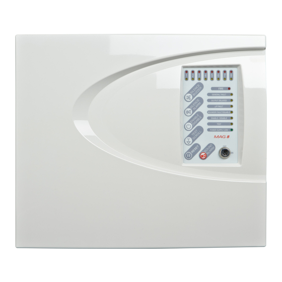
Fire Control Panel MAG8 - Installation and Operation Manual 1. Using the MAG8 Controls LED indication for the status of the zones - see item 1.2. LED indication for the technical faults in the system - see item 1.3. This indication is not visible from the user. -
Page 5: Mag8 Operation Modes
Fire Control Panel MAG8 - Installation and Operation Manual 1.1 MAG8 Operation Modes: MODE Indication Normal • Only the “POWER SUPPLy 230V” green LED is illuminated. • The “FIRE” red LED and the zone red LED will flash together on receipt of a FIRE condition and become steady after the “SILENCE ALARM”... -
Page 6: Led Indication For The System Status
Fire Control Panel MAG8 - Installation and Operation Manual 1.4 LED indication for the system status: Indication FIRE Fire in the premises. (red) GENERAL FAULT Main Fault indicator. (yellow) OUTPUT DELAY Lights permanently at programmed outputs time delay (yellow) (a jumper is set on the TIME DELAY terminal). -
Page 7: Installing The Mag8 Panel
Fire Control Panel MAG8 - Installation and Operation Manual 2. Installing the MAG8 Panel • Choose the best location for the panel position, with an ambient temperature between -5°C and 40°C, away from heating sources, environmental dust and potential water ingress. -
Page 8: Initial Power-Up Of Mag8 Panel
Fire Control Panel MAG8 - Installation and Operation Manual 3. Initial Power-up of MAG8 Panel ATTENTION: It has been assumed that prior to making the connection at the panel, the integrity of the system ALL wiring has been comprehensively tested, including insulation to earth. -
Page 9: Connecting The Sounders Circuits
Fire Control Panel MAG8 - Installation and Operation Manual • Operate ALL detection devices applicable to this zone, to ensure correct receipt of a fire signal and the correct operation of the panel controls. Refer to the User Instructions on the inside of the panel. -
Page 10: Class Change Function
RESET” button to introduce changes. 11. Programming single Panel Mode No jumper is set on the Master or Slave position in Single Panel Mode of the MAG8. In order to program the Single Panel mode: • Check whether there are jumpers set on the Master or Slave position. Remove if any. -
Page 11: Programming Wireless Receiver Mode
The purpose of introducing a Double Action mode is to avoid false alarms. When the MAG8 panel has been programmed to function in this mode, in case of a fire alarm signal, the panel does not starting the sounders at once and waits for the alarm event to be repeated within a specific time interval. - Page 12 Fire Control Panel MAG8 - Installation and Operation Manual Attention: The fire alarm panel MAG8 is capable to distinguish the activation of automatic fire alarm detector and call point. In case of call point activation, the programmed DOUBLE Action mode will be ignored and the sounders will be activated immediately.
-
Page 13: Operating Instructions
Fire Control Panel MAG8 - Installation and Operation Manual 16. Operating Instructions 16.1 sound signalization signal Description After pressing the “ RESET” button and upon the initial start-up of short beeps the panel. Fire and/ or Fault operating mode. The signal can be stopped by Continuous pressing the “... - Page 14 Fire Control Panel MAG8 - Installation and Operation Manual sounders Enable / Disable A sound signalization is activated at every service Mode entering. The signalization is off by pressing “ sILENCE BUZZER” button. To disable the sounders: DISABLE/ ENABLE LED blinks.
- Page 15 Fire Control Panel MAG8 - Installation and Operation Manual “One Man” Test The “One Man” Test mode gives the installer the possibility to test the efficiency of the system - whether the detectors react to smoke, heat, etc. To “One Man” Test a zone: TEST LED will start blinking.
-
Page 16: Connection Diagram
Fire Control Panel MAG8 - Installation and Operation Manual 17. Connection Diagram... -
Page 17: Technical Specifications
-5 to 40°C Storage temperature -20 to 60°C Humidity 0 to 95% Compatible modules MR8 - 8 Relay Module ML - Log Memory Module Attention: It is possible to connect only one module to the MAG8 fire panel at the same time! -
Page 18: Fire Alarm Record
Fire Control Panel MAG8 - Installation and Operation Manual FIRE ALARM RECORD Installation Address: ....................... Contact Person: ....................... Telephone: ....................... Fax: ....................... Date Completed: ....................... Commissioned By: ....................... Contract Reference: ....................... Service Intervals: Monthly / Quarterly / Half yearly / Annually... -
Page 19: Fire Alarm Event Log
Fire Control Panel MAG8 - Installation and Operation Manual FIRE ALARM EvENT LOG FAULT FIRE ZONE ACTION DATE TIME yes/no and Name yes / no number TAKEN TYPE sPARE PARTs KIT Component Description Q-ty Fuse 0.315A, 5x20 Key, 10mm Screw, 2.9x13 mm,... - Page 20 Address: 14A Srebarna Str., 1407 Sofia, Bulgaria Tel: (+359 2) 9694 800, Fax: (+359 2) 962 52 13 e-mail: info@teletek-electronics.bg www.teletek-electronics.com...
Need help?
Do you have a question about the MAG8 and is the answer not in the manual?
Questions and answers