Table of Contents
Advertisement
Quick Links
INSTALLATION
AND PROGRAMMING
MANUAL
Intelligent Interactive Fire Alarm Control Panel
REPEATER
Attention:
This manual contains information on limitations regarding product use and
function and information on the limitations as to liability of the
manufacturer. The entire manual should be carefully read.
The information in this manual is a subject to change without notice!
Advertisement
Table of Contents

Related Manuals for Teletek electronics REPEATER


Summary of Contents for Teletek electronics REPEATER
- Page 1 INSTALLATION AND PROGRAMMING MANUAL Intelligent Interactive Fire Alarm Control Panel REPEATER Attention: This manual contains information on limitations regarding product use and function and information on the limitations as to liability of the manufacturer. The entire manual should be carefully read.
-
Page 2: Table Of Contents
3.3.2 Firmware Update from USB Drive................9 3.3.3 Copying Image File from the Panel to USB Drive ............9 4. FULL HARDWARE RESET..........................9 5. PROGRAMMING OF THE REPEATER PANEL ..................10 5.1. General Information for Programming and Operation..............10 5.2. Codes and Access Levels......................10 6. - Page 3 RAN form at: http://teletek-electronics.com/en/ran-form. The setup and programming included in the technical documentation shall not be regarded as defects. Teletek Electronics bears no responsibility for the loss of programming information in the device being serviced. CONDITIONS FOR WAIVING THE GUARANTEE This guarantee shall apply to defects in products resulting only from improper materials or workmanship, related to its normal use.
-
Page 4: Introduction
1.1. General Description The Repeater is a device that duplicates the information provided by the Simpo, Iris and Iris Pro addressable fire panels in order to help you get information on the current situation in the premises without having to be physically close to the main panel. -
Page 5: Installation
Repeater – Installation and Programming Manual 2. INSTALLATION Fixing elements for the snap mechanism Premoulded holes to bore up with D 4.0 to Use a bush of brass M3x4 (AS 036915) and a screw M3x6 (A 03 06 031) for rear side fastening Use rubber feet e.g. -
Page 6: System Components
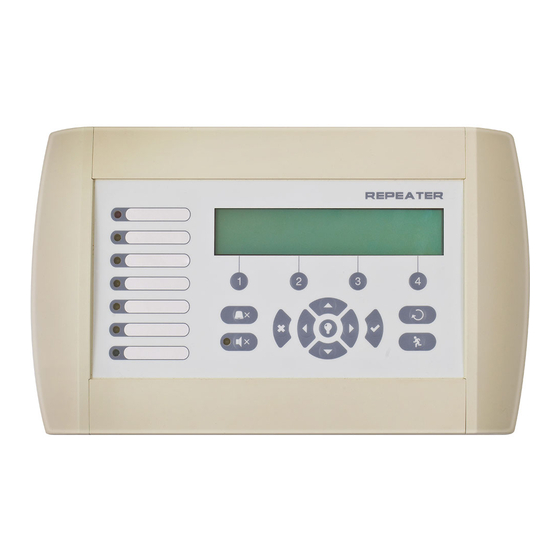
LED is situated next to the button). 2 – Description of the LCD-module The Repeater panel is equipped with letter-digit LCD-module (4 rows x 40 symbols). The user can enter device and zone names using the navigation and control buttons. The display has an adjustable backlight with 20 levels of intensity. -
Page 7: Description Of The Main Pcb (Control Panel)
Repeater – Installation and Programming Manual 5 – Description of control and navigation buttons: Button Action Description The button is active at access levels 1, 2 and 3. The button functionality is deactivation of the internal buzzer. Silence Buzzer The button is active at access levels 2 and 3. The button functionality is deactivation of the sounders in case of fire alarm event. -
Page 8: Programming Types
The specialized ProsTE software is designed for programming of intruder and fire alarm panels produced by Teletek Electronics JSC. To program the Repeater panel you should first to install the ProsTE software on your computer – the program can be downloaded free of charge after registration on the website of the producer: http://www.teletek-electronics.com/en/product/proste-en... -
Page 9: Firmware Update From Usb Drive
SIMPO folder. 4. FULL HARDWARE RESET The full hardware reset of the Repeater allows the engineer to restore all factory settings and access code combinations for level 2 (Maintenance) and 3 (Installer). To perform full hardware reset, follow the steps: 1. -
Page 10: Programming Of The Repeater Panel
5.1. General Information for Programming and Operation The Repeater panel can be programmed directly through the navigation and functional digit buttons on the front panel. The programming menus are organized in a text tree-structure and are viewed on the LCD-display (4 rows x 40 symbols). - Page 11 Repeater – Installation and Programming Manual The access codes could be changed only from level Installer - menu 2) General Settings - submenu 2.1) Access codes. There are different restrictions on the panel functions in the relative access levels, which are...
-
Page 12: Description Of The Operation Modes
6. DESCRIPTION OF THE OPERATION MODES In this section you can find detailed descriptions of all operation modes of the Repeater panel. The modes for reviewing of system events are accessible only from level 1 without entering access code. If no alarm, fault or warning messages, active tests and disablements are present, then the panel is in normal operation mode and only the current day and time is displayed. -
Page 13: Review Of Disablements
Repeater – Installation and Programming Manual 6.3. Review of Disablements The messages for disablements are displayed with normal priority. If no alarm or fault events are present, and there are active disablements in the system, the DISABLED mode is blinking together with the number of the first disablement. -
Page 14: Review Of Warning Messages
Repeater – Installation and Programming Manual After choosing the button (2) TESTS the screen displays: To exit the review of running tests mode, press CANCEL button. 6.5. Review of Warning Messages The messages for warnings are displayed with low priority. If no alarm or fault events or disablements and tests are present, and there are active warnings in the system, the WARNINGS mode is blinking together with the number of the first message. -
Page 15: Silencing The Internal Buzzer
Repeater – Installation and Programming Manual 6.6. Silencing the Internal Buzzer The internal buzzer of the Repeater is signaling in case of activated alarm or fault events in the system. The buzzer silencing is available from every access level without code entry. -
Page 16: Description Of The Programming Menus
Repeater – Installation and Programming Manual 7. DESCRIPTION OF THE PROGRAMMING MENUS The programming menus are accessible from level 2 (Maintenance) and level 3 (Installer) after entering a valid access code. In level 2 could be realized partial programming of parameters, and some values are accessible only for reviewing. -
Page 17: Review Of List Of Events By Date
Repeater – Installation and Programming Manual 7.1.2 Review of List of Events by Date From the main screen of VIEW LOG menu press (2) FROM button. In “FROM” submenu the installer can extract a list of events by date. Set in sequence the day, the month and the last two digits of the year. The edited digit is flashing. -
Page 18: General Settings Menu
Repeater – Installation and Programming Manual 7.2. General Settings Menu This menu allows the installer to make some common settings for the Repeater panel. The menu is accessible from access levels 2 and 3, as for the level to are introduced some restrictions. -
Page 19: Setting The Date And Time
IMPORTANT NOTES! The Repeater panel is equipped with built-in battery for saving the set time and date in case of main or back-up power supply lost. Put a jumper on JP7 terminals on the control panel PCB to enable the built-in battery and saving the set time and date. -
Page 20: Save Configuration Menu
Repeater – Installation and Programming Manual 7.3. Save Configuration Menu Attention: Saving the system configuration is available only from access level 3! In this menu the installer performs saving of the new found devices in the system configuration. The panel will ask for confirmation of the action. -
Page 21: Panels Settings
Repeater – Installation and Programming Manual 7.6.2 Panels Settings To access the PANELS settings, enter in the installer’s menu - 3. NETWORK – 3.2) PANELS. On the screen are listed the panels with their current state the redundant network: • NEW – The panel is new in the system. To save it press button (3) SAVE. - Page 22 Repeater – Installation and Programming Manual APPENDIX A Table: Text and symbols for introducing device and zone names. In device or zone name entering mode every pressing of up/ down arrow button changes the entered letter or symbol. When moving to the next new position the entering starts from the begging of the table.
- Page 23 Repeater – Installation and Programming Manual APPENDIX C Two steps of alarming Algorithm.
- Page 24 Repeater – Installation and Programming Manual APPENDIX D Tree structure of the programming menus. The presented tree structure describes the full access to the programming menus from level 3 – Installer. From access level 2 – Maintenance, some of the programming menus are not displayed or the operation with them is partially limited –...
- Page 25 www.teletek-electronics.com Address: Bulgaria, 1407 Sofia, 14А Srebarna Str. Tel.: +359 2 9694 800, Fax: +359 2 962 52 13 e-mail: info@teletek-electronics.bg...
Need help?
Do you have a question about the REPEATER and is the answer not in the manual?
Questions and answers