Table of Contents
Advertisement
OPERATION
AND MAINTENANCE
MANUAL
Intelligent Interactive Analogue Addressable
Fire Alarm Control Panel
SIMPO
Attention:
This manual contains information on limitations regarding product use and
function and information on the limitations as to liability of the manufacturer.
The entire manual should be carefully read.
The information in this manual is a subject to change without notice!
Advertisement
Table of Contents

Related Manuals for Teletek electronics SIMPO


Summary of Contents for Teletek electronics SIMPO
- Page 1 AND MAINTENANCE MANUAL Intelligent Interactive Analogue Addressable Fire Alarm Control Panel SIMPO Attention: This manual contains information on limitations regarding product use and function and information on the limitations as to liability of the manufacturer. The entire manual should be carefully read.
-
Page 2: Table Of Contents
SIMPO Addressable Fire Alarm Panel – Maintenance Menus Table of Contents 1. INTRODUCTION ................................ 3 1.1. General Description ............................ 3 1.2. General Specifications ..........................3 1.3. Front Panel and Buttons ..........................4 2. OPERATION MODES ..............................6 2.1. Review of Alarm Events ..........................6 2.2. -
Page 3: Introduction
1. INTRODUCTION 1.1. General Description SIMPO is an addressable fire panel with maximum coverage of 48 zones and connecting and up to 2 loops. The panel supports communication protocol Teletek Electronics (SIMPO TTE Loop) and operation with SensoIRIS addressable device series. -
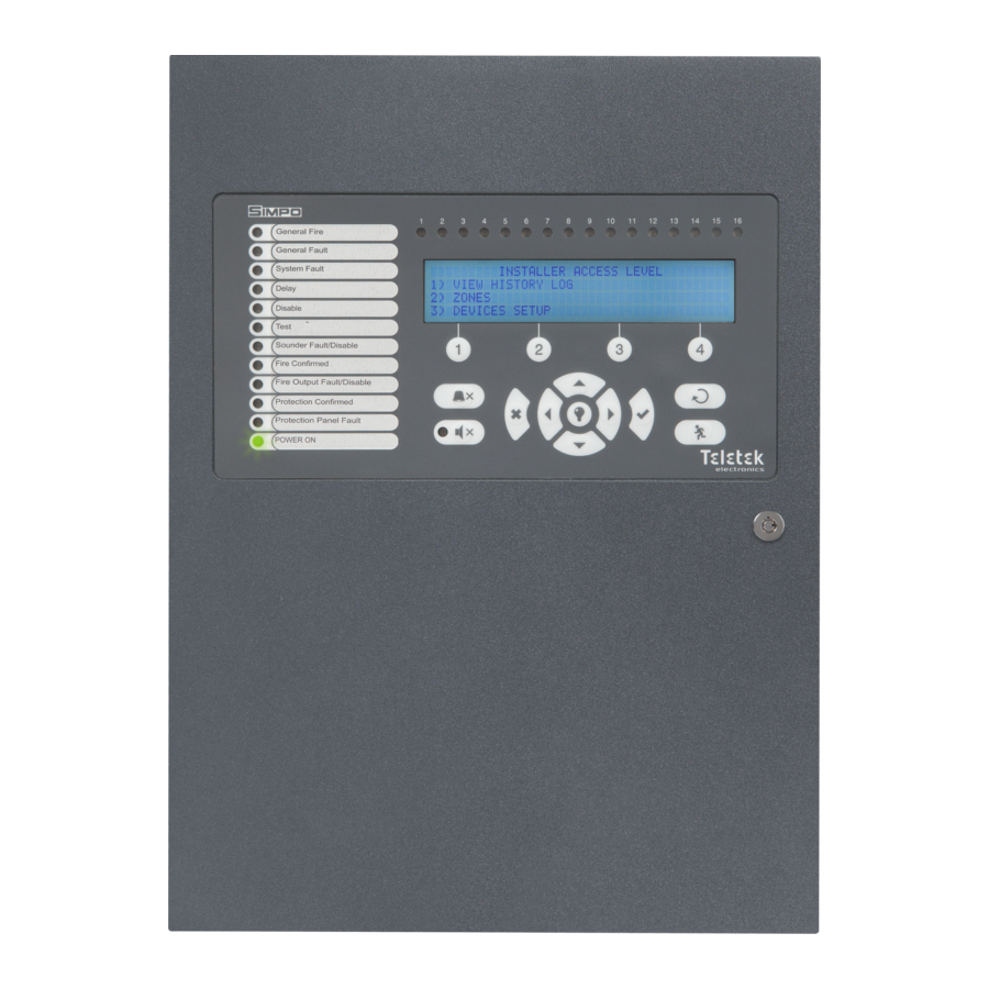
Page 4: Front Panel And Buttons
SIMPO Addressable Fire Alarm Panel – Maintenance Menus 1.3. Front Panel and Buttons Description of the front panel elements: 1 – LED indication for the system status. The descriptions are printed on the paper label and can be changed if needed, including for language change. - Page 5 3 – Description of the LCD-module The SIMPO fire alarm addressable panel is equipped with letter-digit LCD-module (4 rows x 40 symbols). The user can enter device and zone names using the navigation and control buttons. The display has an adjustable backlight with 20 levels of intensity.
-
Page 6: Operation Modes
SIMPO Addressable Fire Alarm Panel – Maintenance Menus 2. OPERATION MODES The regular users (access level 1) can review the current status of the panel for Alarm events, Troubles, etc, without entering special access code for operation. The regular users can silence the internal buzzer and send manually evacuation signal in those cases, when the fire alarm is received from a device. -
Page 7: Review Of Disablements
SIMPO Addressable Fire Alarm Panel – Maintenance Menus item 2.1. The total number of active faults is displayed at the bottom right corner of the screen. Use button (1) to go back to ALARMS mode and reviewing the alarm messages. -
Page 8: Review Of Warning Messages
SIMPO Addressable Fire Alarm Panel – Maintenance Menus The User can review the number of the zone in test mode. For this, select the number of the zone using up/ down arrow buttons (the number of the selected event is blinking) and press ENTER button. -
Page 9: Silencing The Internal Buzzer
CANCEL button. 2.6. Silencing the Internal Buzzer The internal buzzer of addressable fire alarm panel SIMPO is signalling in case of activated alarm or fault events in the system. The buzzer silencing is available from every access level without code entry. -
Page 10: Maintenance Menus
SIMPO Addressable Fire Alarm Panel – Maintenance Menus 3. MAINTENANCE MENUS The Maintenance Menus are accessible after entering a Maintenance access code (default 2222). Maintenance Menus Description Silence buzzer Deactivating Internal Buzzer. Deactivating the Sounders. Silence Sounders During active fire alarms and deactivated/ silenced sounders the LED next the button is lighting up. -
Page 11: Review Of Full Events List
SIMPO Addressable Fire Alarm Panel – Maintenance Menus 3.1.1 Review of Full Events List From the main screen of VIEW LOG menu press (1) VIEW ALL button. The last (newest) event is displayed on the screen. Use the buttons with up and down arrows to review all recorded events one-by-one, as everyone is displayed with date and time of occurring. -
Page 12: Zones Menu
SIMPO Addressable Fire Alarm Panel – Maintenance Menus 3.2. Zones Menu This menu allows the technician to review and change the status of every zone. In the ‘ZONES’ menus the technician can test and enable/ disable the zones. Up to 48 zone numbers are available for settings. The currently edited zone number is blinking. -
Page 13: Disabling Zones
This menu allows the technician to review the status of every device. Up to 250 devices per loop are available for settings (up to 500 when using second loop in the SIMPO panel). In the ‘DEVICES SETUP’ menus the technician can disable the connected detectors, modules and sounders. -
Page 14: Disabling Devices
SIMPO Addressable Fire Alarm Panel – Maintenance Menus 3.3.2 Disabling Devices Every loop device can be disabled, as the panel will not follow the operation of the disabled device and will not respond to fire or fault messages from it. The LED ‘Disable’ on the front panel is lighting on. -
Page 15: Extinguishing Output
SIMPO Addressable Fire Alarm Panel – Maintenance Menus 3.4.2 Extinguishing Output In this submenu the technician can disable/ enable the extinguish output activation. To access the EXTINGUISH submenu, enter in menu - 5. PANEL OUTPUTS – EXITING. (2). The functional button has the following action: (2) - Press to change the status of the extinguish output. -
Page 16: Setting Day/ Night Alarm Modes
IMPORTANT NOTES! The SIMPO panel is equipped with built-in battery for saving the set time and date in case of main or back-up power supply lost. Put a jumper on JP7 terminals on the control panel PCB to enable the built-in battery and saving the set time and date. -
Page 17: Delay Т1
SIMPO Addressable Fire Alarm Panel – Maintenance Menus (1) In PC - Press to enable/ disable the indication for trouble at In PC input. (2) In FP - Press to enable/ disable the indication for trouble at In FP input. -
Page 18: Company Logo
3.7. Active Isolators Menu This is an information menu for reviewing the active isolators (built-in isolator in SensoIRIS devices). The active isolators in the system are displayed as device addresses in the fields “L1” and “L2” for SIMPO loops. 3.8. Access Level 1 Exit from Access Level 2 to Access Level 1. - Page 19 SIMPO Addressable Fire Alarm Panel – Maintenance Menus APPENDIX B Tree structure of the Maintenance menus.
- Page 20 www.teletek-electronics.com Address: Bulgaria, 1407 Sofia, 14А Srebarna Str. Tel.: +359 2 9694 800, Fax: +359 2 962 52 13 e-mail: info@teletek-electronics.bg RevA, 09/ 2020...
Need help?
Do you have a question about the SIMPO and is the answer not in the manual?
Questions and answers