Table of Contents
Advertisement
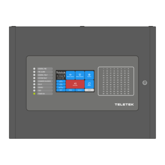
iRIS4
Addressable Fire Alarm Control Panel
Installation Manual
Attention:
This manual contains information on limitations regarding product use and
function and information on the limitations as to liability of the manufacturer.
The entire manual should be carefully read.
The information in this manual is a subject to change without notice!
Advertisement
Table of Contents

Related Manuals for Teletek electronics iRIS4


Summary of Contents for Teletek electronics iRIS4
- Page 1 Addressable Fire Alarm Control Panel Installation Manual Attention: This manual contains information on limitations regarding product use and function and information on the limitations as to liability of the manufacturer. The entire manual should be carefully read. The information in this manual is a subject to change without notice!
-
Page 2: Table Of Contents
- Addressable Fire Alarm Panel – Installation Manual Table of Contents 1. INTRODUCTION ................................ 5 1.1. Basic Information ............................5 1.2. Panel General View ........................... 5 1.3. General Specifications ..........................5 1.3.1. General Technical Specifications....................6 1.3.2. Working Environment ......................... 6 1.3.3. - Page 3 - Addressable Fire Alarm Panel – Installation Manual 1293 DoP No: 246 Teletek Electronics JSC Bulgaria, Sofia 1407, 14А Srebarna Str., Tel.: +359 2 9694 800, Fax: +359 2 962 52 13 e-mail: info@teletek-electronics.bg EN 54-2:1997; EN 54-2:1997/AC:1999; EN 54-2:1997/A1:2006 EN 54-4:1997;...
- Page 4 The manufacturer shall not accept any product, of which no prior notice has been received via the RAN form at: http://teletek-electronics.com/en/ran- form The setup and programming included in the technical documentation shall not be regarded as defects. Teletek Electronics bears no responsibility for the loss of programming information in the device being serviced. CONDITIONS FOR WAIVING THE GUARANTEE This guarantee shall apply to defects in products resulting only from improper materials or workmanship, related to its normal use.
-
Page 5: Introduction
RS485 communication protocol. Only one type of connection can be used in a single network. The iRIS4 fire panel is equipped with a back-up supply battery in case of main power supply failure. The built-in 3V pill battery supports the uninterruptable operation of the real-time clock even in case of mains and back-up power supply failure at the same time. -
Page 6: General Technical Specifications
- Addressable Fire Alarm Panel – Installation Manual 1.3.1. General Technical Specifications • Loops - from 1 to 4 loops • Up to 250 devices per one iRIS8 TTE Loop expander • Max. number of devices - 1000 •... - Page 7 - Addressable Fire Alarm Panel – Installation Manual Main power supply In normal operating conditions the fire panel is powered from the mains voltage line. In case of mains voltage line loss the fire panel is designed to operate with back-up power supply – one or two batteries according the model. The characteristics of the main power supply are as follows: •...
- Page 8 - Addressable Fire Alarm Panel – Installation Manual List of spare parts kits: Element Description iRIS4 Resistor 10K ±5%, 0,25W 2 pcs Jumper 2 pcs Screw 4.2х38, cross slot, DIN7981 (wall mounting – item 2.2) 4 pcs Anchor 6х30mm (wall mounting – item 2.2) 4 pcs Screw M4x40, cross slot, DIN7985 (built-in mounting in 25 mm drywall –...
-
Page 9: Installation
The temperature must be within -5ºС and + 40ºC. The fire panel is not water- proof! Attention: The front cover of iRIS4 panel is mounted to the box bottom with hinges fixed with dismountable rivets. The angle of opening of the front cover must not be greater than 110° - see Figure 3! -
Page 10: Wall Mounting
- Addressable Fire Alarm Panel – Installation Manual 2.2. Wall Mounting • For wall mounting, use the drilling paper template to mark the mounting holes – Figure 4. • For mounting of iRIS4, drill holes Ø6 ÷ Ø8mm. Figure 4 •... -
Page 11: Built-In Mounting
2.3. Built-in Mounting The built-in mounting is designed for iRIS4 panel box and it is applied in 25mm thick drywalls. The built-in mounting is performed with special kit containing: metal base, metal decorative frame and set of fixing elements – Figure 6. -
Page 12: Module Structures
Remove the first row plastic caps from the top and bottom side of iRIS4 box. • Insert the metal bottom of iRIS4 into the metal base and fix them to each other it with the screws. Use 3 pcs of screws M4x12 (DIN 966) for fixing the metal box of iRIS4 to the metal base. - Page 13 - Addressable Fire Alarm Panel – Installation Manual • Prepare the metal boxes for mounting to each other as remove the plastic caps from the top or bottom side of the box bottom according its position in the module structure. For module structures with three or four panels you have to remove all plastic caps from the boxes mounted into the middle.
-
Page 14: System Components
3.1. Front Panel The front panel of iRIS4 presents detailed information of the current system status (1) and activated zones (3) via LED indication. The operation, control and programming of the panel is via the 5 inch TFT screen (2) – Figure 12. -
Page 15: Configuration Of The Basic Modules
- Addressable Fire Alarm Panel – Installation Manual 3.3. Configuration of the Basic Modules The iRIS4 panel is designed with a range of basic modules organized in factory configuration – Figure 14. Elements’ description: 1 - Main power supply unit - see item 4.1. -
Page 16: Basic Modules Description
- Addressable Fire Alarm Panel – Installation Manual 4. BASIC MODULES DESCRIPTION The iRIS4 is delivered with plug connectors (2- and 3-position) mounted to the PCB of the Loop expander(s). The plug connectors are used for quick wire installation. -
Page 17: Connection Diagram Of Main Power Supply Unit And Back-Up Battery
Ri. 4.2. Outputs Control Module The Outputs Control module in iRIS4 addressable fire alarm panel is a structure of two PCBs mounted to each other via interface slot: Monitored outputs PCB and Programmable Relays PCB. -
Page 18: Connection Of Sounders
- Addressable Fire Alarm Panel – Installation Manual Monitored outputs terminals: Terminal Description +24V DC Auxiliary output, 24VA@0.3A Common earth Monitored output for connecting of a sounder, 24V DC/0.5A Monitored output for connecting of auxiliary devices, 24V DC/0.1A. Fault R This output is deactivated in case of system trouble or fault. -
Page 19: Iris8 Tte Loop Expander
) of the devices in the communication line in alarm state must be up to 500mA. If the consumption exceeds this value an overload protection would be turned on. In the configuration of iRIS4 addressable fire alarm panel could be mounted up to 4 loop expanders. 4.3.1. Permissible Cable Length The maximum length of the loop in the system could vary according to the cross-section and the ohmic resistance of the used cable. -
Page 20: Loop Expander Elements Description
- Addressable Fire Alarm Panel – Installation Manual - is the necessary length of the cable for the loop. After calculating, the maximal length of the cable is determined according: · ≤ L ≤ L If L and L... -
Page 21: Adding Loop Expanders
- Addressable Fire Alarm Panel – Installation Manual 4.3.4. Adding Loop Expanders The loop expanders are periphery devices in iRIS4 system configuration. According the physical place of mounting, every loop expander takes a system factory address that cannot be changed – see item for general information about the periphery devices addressing. -
Page 22: Main Control Module Pcb
Figure 24 The connection of iRIS4 panel to IRIS Printer is with a flat interface 800 mm long cable, supplied in the spare parts kit of IRIS Printer - connector types DB9 to DC10. Connect the DB9 connector to Printer terminal of the main control module... -
Page 23: Fat/Fbf Panels Connection
• The connections between iRIS4 fire panel and the adapter box for key safe, and the Dialer are realized using the addressable modules with inputs and outputs (MIO22, MIO22M, MOUT, MINP, MIO04, MIO40), as for the outputs can be used also the panel’s programmable relay outputs –... - Page 24 When the fire is extinguished, the Fire Brigade Officer returns all the keys back to the key safe and locks it. Now the iRIS4 panel must be reset to normal operation mode. After resetting, the adapter of the key safe is locked, the Dialer is returned to stand-by mode, and all of the messages for alarms and warnings are cleared.
-
Page 25: Paso Panels Connection
AND BACKUP POWER SUPPLIES ARE ON! Attention: Connection of max. 6 panels, numbered from 0 to 5, in a network (5 PASO panels and 1 iRIS4 panel)! iRIS4 panel always takes the last number in a network with PASO panels! -
Page 26: Redundant Network Module
4.4.4. Redundant Network Module The iRIS4 addressable fire alarm panel is designed with option for connection in a redundant network with other iRIS4, iRIS8, SIMPO and IRIS/SIMPO Repeater panels (up to 64). The redundant network is based on RS485 interface. - Page 27 - Addressable Fire Alarm Panel – Installation Manual iRIS4 Redundant Network Module External power supply unit Repeater Figure 30 The maximum cable length between two network modules and/ or repeater panel is 1000m. SIMPO Fire panel iRIS4 Fire panel...
-
Page 28: Lan Connection
(up to 64). The LAN connection can be direct panel-to-panel or by means of a HUB via TCP/IP protocol. To operate in LAN network with other iRIS4, iRIS8 and Repeater TFT panels the installer must set for all panels “LAN”... -
Page 29: Methods For Addressing Loop Devices From The Panel
• AUTO ADDRESSING. The auto addressing feature of iRIS4 panel has the purpose to make the installation of the addressable systems easier. By using it the installer could mount all devices without setting address and then do it automatically by a single click in the panel. - Page 30 Routine Maintenance iRIS4 control panel does not require any specific maintenance. To clean the panel’s surface, use a dry cloth. Detergents or solvents should not be used to clean the panel and care must be taken that water does not enter the enclosure.
- Page 31 www.teletek-electronics.com Address: Bulgaria, 1407 Sofia, 14А Srebarna Str. Tel.: +359 2 9694 800, Fax: +359 2 962 52 13 e-mail: info@teletek-electronics.bg 18021294, RevA, 08/ 2022...
Need help?
Do you have a question about the iRIS4 and is the answer not in the manual?
Questions and answers