Table of Contents
Advertisement
Quick Links
PILOT'S INFORMATION
THIS INFORMATION MANUAL IS A NON-OFFICIAL COPY OF THE PILOT'S OPERATING
HANDBOOK AND MAY BE USED FOR GENERAL INFORMATION PURPOSES ONLY.
IT IS NOT KEPT CURRENT AND THEREFORE CANNOT BE USED AS A SUBSTITUTE FOR
AIRWORTHINESS AUTHORITIES APPROVED MANUAL WHICH IS THE ONLY ONE INTENDED
The content of this document is the property of socata. It is supplied in
confidence and commercial security of its contents must be maintained.
It must not be used for any purpose other than that for which it is
supplied, nor may information contained in it be disclosed to unauthorized
persons. It must not be reproduced nor transmitted in any form in whole
or in part without permission in writing from the owners of the Copyright.
Information in this document is subject to change without notice.
DAHER-SOCATA
Customer support
65921 TARBES CEDEX 9
FRANCE
TBM 900
MANUAL
From S/N 1000
P/N T00.DMHPIPYEE0 - EDITION 0 - REVISION 1
CAUTION
FOR OPERATION OF THE AIRPLANE.
© 2014 - socata -
All rights reserved
Printed in FRANCE
Advertisement
Chapters
Table of Contents

Summary of Contents for Daher-Socata TBM 900
- Page 1 TBM 900 PILOT'S INFORMATION MANUAL From S/N 1000 P/N T00.DMHPIPYEE0 - EDITION 0 - REVISION 1 CAUTION THIS INFORMATION MANUAL IS A NON-OFFICIAL COPY OF THE PILOT'S OPERATING HANDBOOK AND MAY BE USED FOR GENERAL INFORMATION PURPOSES ONLY. IT IS NOT KEPT CURRENT AND THEREFORE CANNOT BE USED AS A SUBSTITUTE FOR AIRWORTHINESS AUTHORITIES APPROVED MANUAL WHICH IS THE ONLY ONE INTENDED FOR OPERATION OF THE AIRPLANE.
- Page 2 SECTION 0 PILOT’S OPERATING HANDBOOK SOCATA MODIFICATIONS - INDEX NOTE The standardized name for SOCATA modifications is : MODXXX-XX SUBJECT CLASSIF. MOD70 No. 70-0234-24 Electrical distribution and primary distribution Major 70-0322-00 Evolution of wing tips, tail cone and lights Major 70-0323-71 Propulsion efficiency improvement Major...
- Page 3 SECTION 0 PILOT’S OPERATING HANDBOOK SUBJECT CLASSIF. MOD70 No. 70-0393-25 Replacement of air circuit seal on pilot door minor 70-0400-28 Removal of MT40 transducer minor 70-0401-92 Illuminated push-buttons minor 70-0402-28 Fuel sequencer evolution minor 70-0403-24 Battery firewall modification minor 70-0404-57 Aileron trimming minor NOTE...
- Page 4 SECTION 0 PILOT’S OPERATING HANDBOOK TABLE OF CONTENTS SECTION GENERAL LIMITATIONS EMERGENCY PROCEDURES NORMAL PROCEDURES PERFORMANCE WEIGHT AND BALANCE DESCRIPTION AIRPLANE HANDLING, SERVICING AND MAINTENANCE SUPPLEMENTS Page 0.6 Edition 0 -- October 31, 2013 Rev. 1...
-
Page 5: Table Of Contents
SECTION 1 PILOT’S OPERATING HANDBOOK GENERAL SECTION 1 GENERAL TABLE OF CONTENTS GENERAL ..............1.1.1 THREE VIEW DRAWING . -
Page 6: General
This Handbook contains 9 Sections, and includes the material required by FAR Part 23 to be furnished to the pilot for operation of the TBM 900 airplane. It also contains supplemental data supplied by the manufacturer. The ”GARMIN” G1000 Integrated Flight Deck Cockpit Reference Guide for the Socata TBM 900, No. -
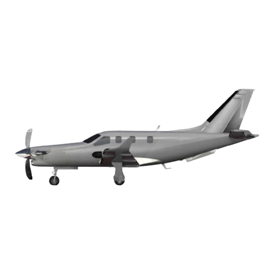
Page 7: Three View Drawing
SECTION 1 PILOT’S OPERATING HANDBOOK GENERAL 1.2 - THREE VIEW DRAWING * Airplane on level field with fully extended FWD shock-absorber Figure 1.2.1 (1/2) - THREE VIEW DRAWING Edition 0 -- October 31, 2013 Page 1.2.1 Rev. 1... - Page 8 SECTION 1 PILOT’S OPERATING HANDBOOK GENERAL Figure 1.2.1 (2/2) - THREE VIEW DRAWING Page 1.2.2 Edition 0 -- October 31, 2013 Rev. 1...
-
Page 9: Descriptive Data
SECTION 1 PILOT’S OPERATING HANDBOOK GENERAL 1.3 - DESCRIPTIVE DATA ENGINE Number of engines : 1 Engine manufacturer : PRATT & WHITNEY CANADA Engine model number : PT6A - 66D Engine type : Free turbine, reverse flow and 2 turbine sections Compressor type : 4 axial stages 1 centrifugal stage... -
Page 10: Fuel
SECTION 1 PILOT’S OPERATING HANDBOOK GENERAL FUEL Total capacity : 301 USG (1140 Litres) Total capacity each tank : 150.5 USG (570 Litres) Total usable : 292 USG (1106 Litres) CAUTION THE USED FUEL MUST CONTAIN AN ANTI-ICE ADDITIVE, IN ACCORDANCE WITH SPECIFICATION MIL-I-27686 or MIL-I-85470. -
Page 11: Engine Oil
SECTION 1 PILOT’S OPERATING HANDBOOK GENERAL ENGINE OIL System total capacity : 12.7 Quarts (12 Litres) (oil cooler included) Usable capacity : 6 Quarts (5.7 Litres) Maximum consumption : 0.14 qt / hr (0.13 l / hr) [0.3 lb/hr (0.136 kg/h)] CAUTION DO NOT MIX DIFFERENT BRANDS OR TYPES Nominal... -
Page 12: Cabin And Entry Dimensions
SECTION 1 PILOT’S OPERATING HANDBOOK GENERAL CABIN AND ENTRY DIMENSIONS Maximum cabin width : 3' 11.64” (1.21 m) Maximum cabin length : 13' 3.45” (4.05 m) Maximum cabin height : 4' (1.22 m) Number of cabin entries : 1 (standard) + 1 ”pilot” door (if installed) Entry width (standard) : 3' 6.52”... -
Page 13: Abbreviations And Terminology
SECTION 1 PILOT’S OPERATING HANDBOOK GENERAL 1.4 - ABBREVIATIONS AND TERMINOLOGY METEOROLOGICAL TERMINOLOGY International standard atmosphere Outside air temperature Static air temperature Atmospheric pressure at the airport reference point. Atmospheric pressure at sea level, at airplane position. NOTE On the ground, the altimeter will indicate ”zero” if it is set to QFE ; it will indicate airport altitude if it is set to QNH. -
Page 14: Power Terminology
SECTION 1 PILOT’S OPERATING HANDBOOK GENERAL Best Angle of Climb Speed is the airspeed which delivers the greatest gain of altitude in the shortest possible horizontal distance. Best Rate of Climb Speed is the airspeed which delivers the greatest gain in altitude in the shortest possible time. - Page 15 SECTION 1 PILOT’S OPERATING HANDBOOK GENERAL Is the distance from the reference datum to the center of gravity (C.G.) of an item. Moment Is the product of the weight of an item multiplied by its arm. Center of gravity (C.G.) : Airplane balance point.
-
Page 16: General Abbreviations
SECTION 1 PILOT’S OPERATING HANDBOOK GENERAL GENERAL ABBREVIATIONS : Ampere or Amber : Air Data Computer : Above ground level ALT. SEL. : Altitude selector ALTI : Altimeter AMP. : Ampere : Autopilot AUTO SEL : Automatic selector AUX BP : Auxiliary boost pump : Battery BAT OVERHEAT: Battery overheat (only with Cadmium-Nickel battery) - Page 17 SECTION 1 PILOT’S OPERATING HANDBOOK GENERAL : Litre : Left : Litre / hour lb or lbs : Pound(s) L / D : Lift-to-drag : Landing LDG GR : Landing gear : Landing Field Elevation LRCR : Long Range Cruise : Low : Low pressure : Long range navigation...
- Page 18 SECTION 1 PILOT’S OPERATING HANDBOOK GENERAL : Gallon U.S : Volt or Voltage WARN : Warning W / S : Windshield Page 1.4.6 Edition 0 -- October 31, 2013 Rev. 1...
-
Page 19: Radio - Navigation Abbreviations
SECTION 1 PILOT’S OPERATING HANDBOOK GENERAL RADIO - NAVIGATION ABBREVIATIONS : Automatic Direction Finder System : Attitude Director Indicator AFCS : Automated Flight Control System AHRS : Attitude and Heading Reference System : Transponder B RNAV : Basic aRea NAVigation : Course Deviation Indicator : Communications Transceivers : Distance Measuring Equipment... - Page 20 SECTION 1 PILOT’S OPERATING HANDBOOK GENERAL 1.5 - CONVERSION FACTORS IMPERIAL AND U.S UNITS TO METRIC UNITS TO IMPERIAL AND METRIC UNITS U.S UNITS MULTIPLY TO OBTAIN MULTIPLY TO OBTAIN FEET 0.3048 METRE METRE 3.2808 FEET INCH 25.4 0.03937 INCH Imp.Gal 4.546 Litre...
- Page 21 SECTION 1 PILOT’S OPERATING HANDBOOK GENERAL Feet 31000 30000 20000 10000 Metres 2500 5000 7500 10000 Figure 1.5.2 - FEET VERSUS METRES Page 1.5.2 Edition 0 -- October 31, 2013 Rev. 1...
- Page 22 SECTION 1 PILOT’S OPERATING HANDBOOK GENERAL 1000 Figure 1.5.3 - INCHES VERSUS MILLIMETRES Edition 0 -- October 31, 2013 Page 1.5.3 Rev. 1...
- Page 23 SECTION 1 PILOT’S OPERATING HANDBOOK GENERAL 8000 6000 4000 2000 1000 2000 3000 4000 Figure 1.5.4 - POUNDS VERSUS KILOGRAMS Page 1.5.4 Edition 0 -- October 31, 2013 Rev. 1...
-
Page 24: Pressure And Standard Atmosphere
SECTION 1 PILOT’S OPERATING HANDBOOK GENERAL 1.6 - PRESSURE AND STANDARD ATMOSPHERE STANDARD ATMOSPHERE Pressure Pressure °C °F altitude (hPa) (ft) 1013.2 + 15.0 + 59.0 2000 942.1 + 11.0 + 51.8 4000 875.0 + 44.6 6000 811.9 + 37.6 8000 752.6 + 30.5... -
Page 25: Pressure Conversion Table
SECTION 1 PILOT’S OPERATING HANDBOOK GENERAL PRESSURE CONVERSION TABLE NOTE The standard pressure of 1013.2 hPa is equal to 29.92 inches of mercury. 28.05 28.08 28.11 28.14 28.17 28.20 28.23 28.26 28.29 28.32 28.35 28.38 28.41 28.44 28.47 28.50 28.53 28.56 28.58 28.61... - Page 26 SECTION 2 PILOT’S OPERATING HANDBOOK LIMITATIONS EASA Approved SECTION 2 LIMITATIONS TABLE OF CONTENTS GENERAL ..............2.1.1 AIRSPEED LIMITATIONS .
- Page 27 SECTION 2 PILOT’S OPERATING HANDBOOK LIMITATIONS EASA Approved MARKINGS ..............2.8.1 INDICATED AIRSPEED .
-
Page 28: General
EASA Approved 2.1 - GENERAL ”TBM 900” is the trade name of the TBM 700 ”N version” airplane (TBM 700 type), which is certified in the Normal Category. This airplane must be flown in compliance with the limits specified by placards or markings and with those given in this Section and throughout the Pilot's Operating Handbook. -
Page 29: Airspeed Limitations
SECTION 2 PILOT’S OPERATING HANDBOOK LIMITATIONS EASA Approved 2.2 - AIRSPEED LIMITATIONS Airspeed limitations and their operational significance are shown in Figure 2.2.1. SPEED KCAS KIAS REMARKS Maximum operating speed Do not intentionally exceed this speed in normal flight category Maneuvering speed Do not make abrupt or full control movements above this speed... -
Page 30: Powerplant Limitations
SECTION 2 PILOT’S OPERATING HANDBOOK LIMITATIONS EASA Approved 2.3 - POWERPLANT LIMITATIONS ENGINE Number of engines : 1 Engine manufacturer : PRATT & WHITNEY CANADA Engine model number : PT6A - 66D Maximum power : 100 % at Np = 2000 RPM Ng limitation : 104.1 % Np limitation :... -
Page 31: Oil
SECTION 2 PILOT’S OPERATING HANDBOOK LIMITATIONS EASA Approved CAUTION DO NOT MIX DIFFERENT BRANDS OR TYPES OF OIL Maximum oil temperature : 104 °C Oil pressure : Minimum : 60 psi Maximum : 135 psi Normal oil pressure is 100 to 135 psi. Oil pressures under 100 psi are undesirable. Under emergency conditions, to complete a flight, a lower oil pressure of 60 psi is permissable at reduced power level not exceeding 80% torque. -
Page 32: Fuel
SECTION 2 PILOT’S OPERATING HANDBOOK LIMITATIONS EASA Approved FUEL Fuel limitations : 2 tanks : 150.5 USG (570 Litres) each Total fuel : 301 USG (1140 Litres) Usable fuel : 292 USG (1106 Litres) Unusable fuel : 9 USG (34 Litres) Maximum fuel imbalance : 15 USG (57 Litres) NOTE Usable fuel can be safely used during all normal airplane maneuvers. -
Page 33: Propeller
SECTION 2 PILOT’S OPERATING HANDBOOK LIMITATIONS EASA Approved PROPELLER Number of propellers : 1 Propeller manufacturer : HARTZELL Propeller model number : HC-E4N-3 / E9083S (K) Propeller diameter : Minimum : 90 inches (2.286 m) Maximum : 91 inches (2.311 m) Propeller blade setting at 30 inches station : Low pitch : 21°... -
Page 34: Starter Operation Limits
SECTION 2 PILOT’S OPERATING HANDBOOK LIMITATIONS EASA Approved 2.4 - STARTER OPERATION LIMITS Starter operation sequence is limited as follows : if Ng ≤ 30 % ..............30 seconds if Ng >... -
Page 35: Weight And C.g. Limits
SECTION 2 PILOT’S OPERATING HANDBOOK LIMITATIONS EASA Approved 2.5 - WEIGHT AND C.G. LIMITS WEIGHT LIMITS Maximum ramp weight (MRW) : 7430 lbs (3370 kg) Maximum takeoff weight (MTOW) : 7394 lbs (3354 kg) Maximum landing weight (MLW) : 7024 lbs (3186 kg) Maximum zero fuel weight (MZFW) : 6032 lbs (2736 kg) Maximum baggage weight : in FWD compartment (non pressurized) : 110 lbs (50 kg) -
Page 36: Limits
SECTION 2 PILOT’S OPERATING HANDBOOK LIMITATIONS EASA Approved C.G. LIMITS -- see Figure 6.4.2 Center of gravity range with landing gear down and flaps up, attitude 0° : Forward limits : 181.3 inches (4.604 m) aft of datum at 4409 lbs (2000 kg) or less (14 % of m.a.c) 183.6 inches (4.664 m) aft of datum at 6250 lbs (2835 kg) (18 % of m.a.c) 185.3 inches (4.707 m) aft of datum at 6579 lbs (2984 kg) (20.85 % of m.a.c) 187 inches (4.752 m) aft of datum at all weights above 7024 lbs (3186 kg) (23.8 % of m.a.c) -
Page 37: Operation Limits
SECTION 2 PILOT’S OPERATING HANDBOOK LIMITATIONS EASA Approved 2.6 - OPERATION LIMITS MANEUVER LIMITS This airplane is certified in the normal category. The normal category is applicable to airplanes intended for non-aerobatic operations. Non-aerobatic operations include any maneuvers incidental to normal flying, stalls (except whip stalls), lazy eights, chandelles, and steep turns in which the angle of bank is no more than 60°. -
Page 38: Gfc 700 Autopilot Limits
SECTION 2 PILOT’S OPERATING HANDBOOK LIMITATIONS EASA Approved GFC 700 AUTOPILOT LIMITS During autopilot operation, a pilot with seat belt fastened must be seated at the left or right position. The autopilot and yaw damper must be OFF during takeoff and landing. Do not engage autopilot below 1000 ft (300 m) above ground level in cruise or climb. - Page 39 SECTION 2 PILOT’S OPERATING HANDBOOK LIMITATIONS EASA Approved For flight planning purposes, in areas where SBAS coverage is not available, the pilot must check RAIM availability. Within the United States, RAIM availability can be determined using the G1000 WFDE Prediction program, part number 006-A0154-01 (010-G1000-00) or later approved version with GARMIN GA36 and GA37 antennas selected, or the FAA's en route and terminal RAIM prediction website: www.raimprediction.net, or by contacting a Flight Service Station.
-
Page 40: Sid/Star
SECTION 2 PILOT’S OPERATING HANDBOOK LIMITATIONS EASA Approved ”GPS”, ”or GPS”, and ”RNAV (GPS)” instrument approaches using the G1000 System are prohibited unless the pilot verifies and uses the current Navigation database. GPS based instrument approaches must be flown in accordance with an approved instrument approach procedure that is loaded from the Navigation database. -
Page 41: Icing Conditions
SECTION 2 PILOT’S OPERATING HANDBOOK LIMITATIONS EASA Approved ICING CONDITIONS In any case of icing conditions, first refer to particular procedures described in Chapter 4.5 (normal procedures) and in case of unforeseen icing conditions, refer in addition to the emergency procedure described in Chapter 3.13. SEVERE ICING CONDITIONS WARNING SEVERE ICING MAY RESULT FROM ENVIRONMENTAL CONDITIONS OUTSIDE OF THOSE... -
Page 42: Equipment Required Depending On Type Of Operation
SECTION 2 PILOT’S OPERATING HANDBOOK LIMITATIONS EASA Approved EQUIPMENT REQUIRED DEPENDING ON TYPE OF OPERATION The airplane is approved for day & night VFR and day & night IFR operations when appropriate equipment is installed and operating correctly. The type certification for each use requires the following equipment. The equipment must be installed and operate perfectly according to the indicated type of use. - Page 43 SECTION 2 PILOT’S OPERATING HANDBOOK LIMITATIONS EASA Approved 4) Engine instruments Torquemeter Propeller tachometer Interturbine temperature indicator (ITT) Gas generator tachometer (Ng) Oil pressure indicator Oil temperature indicator 5) Various indicators Fuel gauge indicators (2) Voltmeter Ammeter Outside air temperature 6) Installations Fuel mechanical pump (main) Fuel electrical pump (auxiliary)
- Page 44 SECTION 2 PILOT’S OPERATING HANDBOOK LIMITATIONS EASA Approved Night VFR 1) All equipment required for day VFR 2) Attitude display indicator 3) Instrument lighting 4) Instrument panel lighting 5) Emergency lighting 6) Vertical speed indicator 7) Navigation lights (4) 8) Anticollision lights (2) 9) Landing light 1) All equipment required for day VFR 2) All equipment required for night VFR (if flight is performed during night)
-
Page 45: Altitude Operating Limits
SECTION 2 PILOT’S OPERATING HANDBOOK LIMITATIONS EASA Approved Flight into icing conditions 1) All equipment required for IFR flight 2) Propeller deicing 3) L.H. windshield deicing 4) Airframe, stabilizer and elevator horn deicing 5) Wing leading edge inspection light (if night flight) 6) Stall warning deicing 7) Inertial separator 8) Garmin annunciation ”Airspeed, Airspeed”... -
Page 46: Enhanced Mode S
SECTION 2 PILOT’S OPERATING HANDBOOK LIMITATIONS EASA Approved ENHANCED MODE S The installed Mode S system satisfies the data requirements of ICAO Doc 7030/4, Regional Supplementary Procedures for SSR Mode S Enhanced Surveillance in designated European airspace. The capability to transmit data parameters is shown in column 2 : Parameter Available (A) / Not Available (NA) -
Page 47: Miscellaneous Limits
SECTION 2 PILOT’S OPERATING HANDBOOK LIMITATIONS EASA Approved 2.7 - MISCELLANEOUS LIMITS SEATING LIMITS C.G. 2 front seats at 178.5 in. (4.534 m) With 4-seat accommodation or 6-seat accommodation 2 intermediate seats at 224.8 in. (5.710 m) With 6-seat accommodation Rear bench (2 seats) at 267.1 in. - Page 48 SECTION 2 PILOT’S OPERATING HANDBOOK LIMITATIONS EASA Approved 2.8 - MARKINGS INDICATED AIRSPEED Indicated airspeed markings and their color code significance are shown in Figure 2.8.1. KIAS SIGNIFICANCE MARKING (Value or range) Red line Below 65 Full Flap Operating Range White line 65 - 122 Lower limit is maximum weight...
- Page 49 SECTION 2 PILOT’S OPERATING HANDBOOK LIMITATIONS EASA Approved ENGINE INSTRUMENTS Engine instrument markings and their color code significance are shown in Figure 2.8.3. Green Yellow Line or Arc Line or Arc Line or Arc Red Line --------- --------- --------- --------- INDICATION Caution Minimum...
- Page 50 SECTION 2 PILOT’S OPERATING HANDBOOK LIMITATIONS EASA Approved 2.9 - PLACARDS Under L.H. front side window Calibration chart on compass and on windshield post Steer Steer DATE : RADIO ON On pressurized baggage compartment partition wall 100 kg - - 220 lbs MAXIMUM IT IS THE PILOT’S RESPONSIBILITY TO CHECK THAT ALL THE BAGGAGES ARE PROPERLY SECURED...
- Page 51 SECTION 2 PILOT’S OPERATING HANDBOOK LIMITATIONS EASA Approved (3)a For the small cargo net, on frame C13bis (3)b For the large cargo net, on R.H. side upholstery panel, in the rear baggage compartment (3)c On FWD baggage compartment door frame (non pressurized) 50 kg - - 110 lbs MAXIMUM FOR LOADING INSTRUCTIONS SEE ”WEIGHT AND BALANCE DATA”...
- Page 52 SECTION 2 PILOT’S OPERATING HANDBOOK LIMITATIONS EASA Approved Under GCU 475 control unit on pedestal console On fuel selector Near fuel tank caps Edition 0 -- October 31, 2013 Page 2.9.3 Rev. 1...
- Page 53 SECTION 2 PILOT’S OPERATING HANDBOOK LIMITATIONS EASA Approved On internal face of L.H. engine cowling Oil system capacity 12 l 12.7 qt On landing gear emergency control access door LDG GEAR EMERGENCY ACCESS PULL Under window, at L.H. Intermediate seat (10) On rear passenger's table casing TABLE MUST BE STOWED DURING TAKEOFF AND LANDING...
- Page 54 SECTION 2 PILOT’S OPERATING HANDBOOK LIMITATIONS EASA Approved (12) On nose gear door (13) On nose gear leg NOSE LANDING GEAR TIRE PRESSURE : 6,5 bar 94 psi (14) On main gear leg MAIN LANDING GEAR TIRE PRESSURE : 8,96 bar 130 psi (15) On engine cowling, in front of compartment door...
- Page 55 SECTION 2 PILOT’S OPERATING HANDBOOK LIMITATIONS EASA Approved (16) On ”pilot” door - External side (if installed) (17) On access door - External side (18) On outer fuselage skin aft of access door and in the cabin forward of access door Page 2.9.6 Edition 0 -- October 31, 2013 Rev.
- Page 56 SECTION 2 PILOT’S OPERATING HANDBOOK LIMITATIONS EASA Approved (19) On access door - Internal side (20) On ”pilot” door - Internal side (if installed) (21) On emergency exit handle Marking on cover Marking on handle Edition 0 -- October 31, 2013 Page 2.9.7 Rev.
- Page 57 SECTION 2 PILOT’S OPERATING HANDBOOK LIMITATIONS EASA Approved (22) On last step of stairs STAIRS MAX LOAD : ONE PERSON (23) On R.H. access door jamb (24) On R.H. side at front seat level and on the first rear passengers masks container (R.H. side on the ceiling) (25) On rear passengers masks containers Page 2.9.8...
- Page 58 SECTION 2 PILOT’S OPERATING HANDBOOK LIMITATIONS EASA Approved (26) On internal face of the oxygen cylinder service door (27) On the oxygen service door (28) On emergency locator transmitter inspection door (29) On the potty seat curtain (if installed), on pilot's side CURTAIN MUST BE STOWED FOR TAKE- -OFF AND LANDING Edition 0 -- October 31, 2013 Page 2.9.9...
- Page 59 SECTION 3 PILOT’S OPERATING HANDBOOK EMERGENCY PROCEDURES EASA Approved SECTION 3 EMERGENCY PROCEDURES TABLE OF CONTENTS GENERAL ..............3.1.1 FAILURES WITH IMMEDIATE ACTION REQUIRED AND RED CAS MESSAGES .
- Page 60 SECTION 3 PILOT’S OPERATING HANDBOOK EMERGENCY PROCEDURES EASA Approved AMBER CAS MESSAGES ............3.3.1 ”AUTO SEL”...
- Page 61 SECTION 3 PILOT’S OPERATING HANDBOOK EMERGENCY PROCEDURES EASA Approved PRESSURIZATION MISCELLANEOUS ..........3.8.1 CABIN NOT DEPRESSURIZED AFTER LANDING .
- Page 62 SECTION 3 PILOT’S OPERATING HANDBOOK EMERGENCY PROCEDURES EASA Approved 3.1 - GENERAL The recommended procedures for different failures or emergency situations are provided in this Section. Emergency procedures associated with optional or particular equipment which require pilot's operating handbook supplements are provided in Section 9 ”Supplements”. The pilot must know procedures given in this section and be prepared to take appropriate action should an emergency arise.
- Page 63 SECTION 3 PILOT’S OPERATING HANDBOOK EMERGENCY PROCEDURES EASA Approved 3.2 - FAILURES WITH IMMEDIATE ACTION REQUIRED AND RED CAS MESSAGES ENGINE FIRE ON GROUND ”ITT” Symptoms : ITT increasing, red warning CAS message ON, smoke, ... 1 - Throttle ..............CUT OFF 2 - ”BLEED”...
- Page 64 SECTION 3 PILOT’S OPERATING HANDBOOK EMERGENCY PROCEDURES EASA Approved CABIN FIRE ON GROUND 1 - Throttle ..............CUT OFF 2 - Brakes .
-
Page 65: Pilot's Operating Handbook
SECTION 3 PILOT’S OPERATING HANDBOOK EMERGENCY PROCEDURES EASA Approved ENGINE FIRE IN FLIGHT ”ITT” Symptoms : ITT increasing, red warning CAS message ON, smoke, ... FLY THE AIRPLANE 1 - Throttle ..............CUT OFF 2 - ”AUX BP”... -
Page 66: Cabin Electrical Fire Or Smoke During Flight
SECTION 3 PILOT’S OPERATING HANDBOOK EMERGENCY PROCEDURES EASA Approved CABIN ELECTRICAL FIRE SMOKE DURING FLIGHT FLY THE AIRPLANE 1 - OXYGEN and GOGGLES ......... . . USE AS REQUIRED If the origin is known : 2 - CIRCUIT BREAKER... - Page 67 SECTION 3 PILOT’S OPERATING HANDBOOK EMERGENCY PROCEDURES EASA Approved ENGINE FAILURE AT TAKE OFF FLY THE AIRPLANE BEFORE ROTATION 1 - Throttle ..............Flight IDLE 2 - Braking .
- Page 68 SECTION 3 PILOT’S OPERATING HANDBOOK EMERGENCY PROCEDURES EASA Approved ENGINE FAILURE AT TAKE OFF FLY THE AIRPLANE AFTER ROTATION 1 - ”MAN OVRD” control ..........FULL FORWARD If successful Fly the airplane using the ”MAN OVRD”...
-
Page 69: Engine Failure During Flight
SECTION 3 PILOT’S OPERATING HANDBOOK EMERGENCY PROCEDURES EASA Approved ENGINE FAILURE DURING FLIGHT FLY THE AIRPLANE 1 - AUTOPILOT ............DISCONNECT 2 - Throttle . -
Page 70: Air Start
SECTION 3 PILOT’S OPERATING HANDBOOK EMERGENCY PROCEDURES EASA Approved AIR START CAUTION THE STARTER CANNOT OPERATE IF THE ”GENERATOR” SELECTOR IS ON ”ST-BY” 1 - ”BLEED” switch ............. OFF/RST CAUTION ”BLEED”... -
Page 71: Forced Landing
SECTION 3 PILOT’S OPERATING HANDBOOK EMERGENCY PROCEDURES EASA Approved FORCED LANDING 1 - Throttle ..............CUT OFF 2 - Tank selector . - Page 72 SECTION 3 PILOT’S OPERATING HANDBOOK EMERGENCY PROCEDURES EASA Approved CRACK IN COCKPIT WINDOW OR WINDOW PANEL FLY THE AIRPLANE 1 - DESCEND SLOWLY 2 - Reduce cabin ΔP ....by setting .
- Page 73 SECTION 3 PILOT’S OPERATING HANDBOOK EMERGENCY PROCEDURES EASA Approved RUNAWAY OF TRIM FLY THE AIRPLANE 1 - ”AP / TRIMS DISC” push-button ........PRESSED AND HELD The three trim tabs are disconnected and runaway stops 2 - ”AP / TRIMS”...
- Page 74 SECTION 3 PILOT’S OPERATING HANDBOOK EMERGENCY PROCEDURES EASA Approved EMERGENCY DESCENTS MAXIMUM RATE DESCENT FLY THE AIRPLANE 1 - Throttle ..............Flight IDLE 2 - OXYGEN .
- Page 75 SECTION 3 PILOT’S OPERATING HANDBOOK EMERGENCY PROCEDURES EASA Approved EMERGENCY DESCENTS MAXIMUM RANGE DESCENT FLY THE AIRPLANE 1 - Throttle ..............CUT OFF 2 - Flaps .
- Page 76 SECTION 3 PILOT’S OPERATING HANDBOOK EMERGENCY PROCEDURES EASA Approved ”CD” player ..............”INSTR / CABIN / ACCESS”...
- Page 77 SECTION 3 PILOT’S OPERATING HANDBOOK EMERGENCY PROCEDURES EASA Approved EMERGENCY DESCENT PROFILES Figure 3.2.2 - EMERGENCY DESCENT PROFILES Edition 0 -- October 31, 2013 Page 3.2.15 Rev. 1...
- Page 78 SECTION 3 PILOT’S OPERATING HANDBOOK EMERGENCY PROCEDURES EASA Approved INADVERTENT SPINS (Voluntary spins are prohibited) 1 - CONTROL WHEEL ......... . . NEUTRAL : PITCH ROLL 2 - RUDDER .
- Page 79 SECTION 3 PILOT’S OPERATING HANDBOOK EMERGENCY PROCEDURES EASA Approved LEFT PFD FAILURE FLY THE AIRPLANE AT TAKE OFF 1 - Fly the airplane manually ........using Stand-by Instruments 2 - ”AP / TRIMS DISC”...
- Page 80 SECTION 3 PILOT’S OPERATING HANDBOOK EMERGENCY PROCEDURES EASA Approved TIRE BLOWOUT DURING LANDING 1 - Control direction ........with brakes and nose wheel steering 2 - REVERSE .
- Page 81 SECTION 3 PILOT’S OPERATING HANDBOOK EMERGENCY PROCEDURES EASA Approved SMOKE ELIMINATION 1 - Smoke origin ............. . IDENTIFY 2 - Oxygen and goggles .
- Page 82 SECTION 3 PILOT’S OPERATING HANDBOOK EMERGENCY PROCEDURES EASA Approved TOTAL LOSS OF ELECTRICAL POWER 1 - Maintain airplane control. 2 - PRESS ANY KEY on ESI-2000 ......... within 5 minutes (FOR BATTERY POWER) 3 - Use the ESI-2000 for...
-
Page 83: Bleed Temp
SECTION 3 PILOT’S OPERATING HANDBOOK EMERGENCY PROCEDURES EASA Approved ”BLEED TEMP” ”BLEED OFF” Indicates overheat of bleed air system. Normally this leads to BLEED cut off and to amber warning CAS message appearance. FLY THE AIRPLANE Should automatic cut off occur or not : 1 - If possible . -
Page 84: Cabin Altitude
SECTION 3 PILOT’S OPERATING HANDBOOK EMERGENCY PROCEDURES EASA Approved ”CABIN ALTITUDE” Indicates a cabin altitude over 10000 ft ± 500 ft. 1 - Pressurization indicator ............CHECK If cabin altitude >... -
Page 85: Door
SECTION 3 PILOT’S OPERATING HANDBOOK EMERGENCY PROCEDURES EASA Approved ”DOOR” Indicates that one of the door latches of the access door or (if installed) of the ”pilot” door is not correctly locked. On ground : Check the correct locking, as well as the latches position of the access door and (if installed) of the pilot door ”DOOR”... -
Page 86: Elec Feath Fault
SECTION 3 PILOT’S OPERATING HANDBOOK EMERGENCY PROCEDURES EASA Approved ”ELEC FEATH FAULT” Indicates a propeller feathering system malfunction. 1 - ”FEATHER” ....circuit breaker . -
Page 87: Flaps Asym
SECTION 3 PILOT’S OPERATING HANDBOOK EMERGENCY PROCEDURES EASA Approved ”FLAPS ASYM” FLY THE AIRPLANE Indicates a dissymmetry of flap deflection. This immediately stops the flap motor and prevents further operation of the flaps. 1 - ”FLAPS” ..... . . circuit breaker . -
Page 88: Fuel Press
SECTION 3 PILOT’S OPERATING HANDBOOK EMERGENCY PROCEDURES EASA Approved ”FUEL PRESS” Indicates a fuel pressure drop at ”HP” engine pump inlet FLY THE AIRPLANE 1 - Remaining fuel ..............CHECK 2 - Tank selector . -
Page 89: Itt
SECTION 3 PILOT’S OPERATING HANDBOOK EMERGENCY PROCEDURES EASA Approved ”ITT” A - During engine start : STOP ............the STARTING procedure. -
Page 90: Oil Press
SECTION 3 PILOT’S OPERATING HANDBOOK EMERGENCY PROCEDURES EASA Approved ”OIL PRESS” ”OIL PRESS” RED WARNING CAS MESSAGE Indicates that oil pressure is below 60 PSI. 1 - Oil pressure indicator ............CHECK If the indicated pressure is in the green sector : 2 - Land as soon as possible... - Page 91 SECTION 3 PILOT’S OPERATING HANDBOOK EMERGENCY PROCEDURES EASA Approved 3.3 - AMBER CAS MESSAGES ”AUTO SEL” Indicates that there is no more automatic control mode running. FLY THE AIRPLANE 1 - ”FUEL SEL” switch ............. AUTO If it is on ”AUTO”, failure is confirmed 2 - ”FUEL SEL”...
- Page 92 SECTION 3 PILOT’S OPERATING HANDBOOK EMERGENCY PROCEDURES EASA Approved ”AUX BOOST PMP ON” Indication is normal if ”AUX BP” fuel switch is in ON position FLY THE AIRPLANE If ”AUX BP” fuel switch is in AUTO position : 1 - RESET to .
- Page 93 SECTION 3 PILOT’S OPERATING HANDBOOK EMERGENCY PROCEDURES EASA Approved ”BAT AMP” BATTERY current over 50A while on ground. After starting the engine with airplane power, a battery charge above 50 amperes is normal. CAUTION DO NOT TAKE OFF IF BATTERY CHARGE > 50 AMPERES If this indication remains steady at a high value, it may be due to a battery or generation system failure.
- Page 94 SECTION 3 PILOT’S OPERATING HANDBOOK EMERGENCY PROCEDURES EASA Approved ”BAT OFF” Indicates that : the ”SOURCE” selector has been positioned on OFF or the battery plug is disconnected FLY THE AIRPLANE 1 - ”SOURCE” selector ............. . 2 - ”SOURCE”...
- Page 95 SECTION 3 PILOT’S OPERATING HANDBOOK EMERGENCY PROCEDURES EASA Approved ”BLEED OFF” Indicates that the pressurization system is not running possibly due to : failure or ”BLEED” switch on ”OFF/RST” position 1 - CHECK ”BLEED” switch position and ........CORRECT 2 - If possible, reduce power FLY THE AIRPLANE...
- Page 96 SECTION 3 PILOT’S OPERATING HANDBOOK EMERGENCY PROCEDURES EASA Approved ”CHIP” Indicates an oil chip detection. 1 - LAND AS SOON AS PRACTICAL FLY THE AIRPLANE 2 - Or DO NOT TAKE OFF ..........airplane is grounded 3 - INFORM maintenance center Page 3.3.6...
- Page 97 SECTION 3 PILOT’S OPERATING HANDBOOK EMERGENCY PROCEDURES EASA Approved ”FRONT CARGO DOOR” FORWARD BAGGAGE DOOR OPEN 1 - On the ground ............. . CORRECT 2 - IN THE AIR FLY THE AIRPLANE...
- Page 98 SECTION 3 PILOT’S OPERATING HANDBOOK EMERGENCY PROCEDURES EASA Approved ”FUEL IMBALANCE” Indicates fuel tanks imbalanced by more than 15 USG for more than 30 seconds. If ”FUEL SEL” on AUTO mode SELECT the fullest Tank ......by pressing the ”SHIFT”...
- Page 99 SECTION 3 PILOT’S OPERATING HANDBOOK EMERGENCY PROCEDURES EASA Approved ”FUEL LOW L-R” Indicates a level drop in the corresponding tank. 1 - Corresponding gage ............CHECK 2 - Check the other tank .
- Page 100 SECTION 3 PILOT’S OPERATING HANDBOOK EMERGENCY PROCEDURES EASA Approved ”GPU DOOR” GPU DOOR OPEN 1 - On the ground ............. . CORRECT 2 - IN THE AIR FLY THE AIRPLANE...
- Page 101 SECTION 3 PILOT’S OPERATING HANDBOOK EMERGENCY PROCEDURES EASA Approved ”IGNITION” IGNITION EXCITER IS RUNNING 1 - CHECK ............IGNITION switch position 2 - If weather permits .
- Page 102 SECTION 3 PILOT’S OPERATING HANDBOOK EMERGENCY PROCEDURES EASA Approved ”INERT SEP FAIL” Symptoms : ”INERT SEP ON” Warning does not appear within 50 seconds following ”INERT SEP” switch setting ON Inertial separator not retracted after 50 seconds following ”INERT SEP” switch setting OFF. Circuit breaker ”INERT DE ICE”...
- Page 103 SECTION 3 PILOT’S OPERATING HANDBOOK EMERGENCY PROCEDURES EASA Approved ”LOW LVL FAIL L-R” FUEL LOW LEVEL SENSOR FAILURE CHECK ............Fuel Remaining in Tanks TAKE DECISION If any doubt...
- Page 104 SECTION 3 PILOT’S OPERATING HANDBOOK EMERGENCY PROCEDURES EASA Approved ”LOW VOLTAGE” normal functioning on MAIN GEN 1 - Voltmeter voltages ............
- Page 105 SECTION 3 PILOT’S OPERATING HANDBOOK EMERGENCY PROCEDURES EASA Approved ”MAIN GEN” Indicates that ”GENERATOR” selector has been positioned to OFF or ST-BY, or main generator is cut off 1 - If necessary ............. . . CORRECT 2 - If warning persists .
- Page 106 SECTION 3 PILOT’S OPERATING HANDBOOK EMERGENCY PROCEDURES EASA Approved ”MAIN GEN” ”LOW VOLTAGE” with GENERATOR selector on ”ST-BY” (after MAIN GEN failure) functioning on ST-BY GENERATOR 1 - ”GENERATOR” selector ............MAIN 2 - ”MAIN GENERATOR RESET”...
- Page 107 SECTION 3 PILOT’S OPERATING HANDBOOK EMERGENCY PROCEDURES EASA Approved If conditions do not allow : 13 - Manually disconnect ancillary systems as follows : ”AIRFRAME DE ICE” switch ..........”ICE LIGHT”...
- Page 108 SECTION 3 PILOT’S OPERATING HANDBOOK EMERGENCY PROCEDURES EASA Approved ”OIL TEMP” With or without : ”OIL PRESS” RED WARNING CAS MESSAGE Indicates that oil temperature is below 0°C or above 104°C 1 - Oil temperature indicator ........... . . CHECK If the indicated temperature is in the green sector : 2 - Land as soon as possible...
- Page 109 SECTION 3 PILOT’S OPERATING HANDBOOK EMERGENCY PROCEDURES EASA Approved ”PITOT NO HT L-R” Indicates a heating failure of the corresponding probe. ”PITOT NO HT L” LEFT Icing conditions may alter L.H. airspeed indications 1 - AVOID icing conditions FLY THE AIRPLANE If it is not possible : 2 - Perform moderate descent or climb attitudes overshoot and stall warning system are always operating...
- Page 110 SECTION 3 PILOT’S OPERATING HANDBOOK EMERGENCY PROCEDURES EASA Approved ”PROP DEICE FAIL” Symptoms : Propeller deicing green light is not lit Propeller vibrations 1 - REDUCE power FLY THE AIRPLANE 2 - ACTUATE ..... . Throttle .
- Page 111 SECTION 3 PILOT’S OPERATING HANDBOOK EMERGENCY PROCEDURES EASA Approved ”STALL NO HEAT” Correct operation of the aural stall warning may be altered by severe or prolonged icing. MONITOR and MAINTAIN minimum airspeed according to airplane configuration and icing conditions FLY THE AIRPLANE Edition 0 -- October 31, 2013 Page 3.3.21 Rev.
- Page 112 SECTION 3 PILOT’S OPERATING HANDBOOK EMERGENCY PROCEDURES EASA Approved ”VACUUM LOW” Low vacuum may lead to malfunctioning of LEADING EDGE DEICING and PRESSURIZATION MONITOR If necessary, fly to an altitude ≤ 10000 ft and return to VMC conditions as soon as possible. FLY THE AIRPLANE ”BLEED”...
- Page 113 SECTION 3 PILOT’S OPERATING HANDBOOK EMERGENCY PROCEDURES EASA Approved 3.4 - ENGINE MISCELLANEOUS ENGINE REGULATION DISCREPANCY, POWER LOSS, THROTTLE CONTROL LOSS (1/2) 1 - If circumstances allow : Throttle ..............Flight IDLE 2 - Confirm engine still running 3 - Tank selector...
- Page 114 SECTION 3 PILOT’S OPERATING HANDBOOK EMERGENCY PROCEDURES EASA Approved ENGINE REGULATION DISCREPANCY, POWER LOSS, THROTTLE CONTROL LOSS (2/2) If minimum power obtained is excessive : 1 - Reduce airspeed by setting airplane in nose-up attitude at IAS < 178 KIAS 2 - ”INERT SEP”...
- Page 115 SECTION 3 PILOT’S OPERATING HANDBOOK EMERGENCY PROCEDURES EASA Approved GOVERNOR REGULATION CONTROL NOT OPERATING May indicate a failure of the governor control. 1 - Continue the flight. 2 - If Np < 2000 RPM, do not perform a go-around and do not use the reverse. In that case, the go-around performance and the reverse efficiency might be lower than expected.
- Page 116 SECTION 3 PILOT’S OPERATING HANDBOOK EMERGENCY PROCEDURES EASA Approved EXCESSIVE PROPELLER ROTATION SPEED Indicates : a propeller governor failure In that case, the propeller overspeed limiter will limit initially the rotation speed to 2100 RPM approximately. or a propeller governor and overspeed limiter failure In that case, only the torque limiter operates to limit the power.
- Page 117 SECTION 3 PILOT’S OPERATING HANDBOOK EMERGENCY PROCEDURES EASA Approved ENGINE DOES NOT STOP ON GROUND If the engine does not stop when the Throttle is set to CUT OFF, proceed as follows : 1 - ”AP / TRIMS” switch ............. . 2 - ”INT LIGHTS”...
- Page 118 SECTION 3 PILOT’S OPERATING HANDBOOK EMERGENCY PROCEDURES EASA Approved 3.5 - GEAR AND FLAPS FAILURES LANDING GEAR RETRACTION DISCREPANCY NOTE : Symptoms have to be considered at the end of the sequence. Symptoms : ”GEAR UNSAFE” CAS message and ”GEAR UNSAFE” red warning light ON. Amber light flashing and 3 green lights OFF.
- Page 119 SECTION 3 PILOT’S OPERATING HANDBOOK EMERGENCY PROCEDURES EASA Approved LANDING GEAR EXTENSION DISCREPANCY NOTE : Symptoms have to be considered at the end of the sequence. Symptoms ”GEAR UNSAFE” CAS message and ”GEAR UNSAFE” red warning light ON. Amber light flashing and 0 to 3 green light(s) OFF. Actions Maintain IAS ≤...
- Page 120 SECTION 3 PILOT’S OPERATING HANDBOOK EMERGENCY PROCEDURES EASA Approved EMERGENCY GEAR EXTENSION (1/2) NOTE : This procedure has to be followed in case of any doubt about the gear extension. Maintain IAS ≤ 150 KIAS 1 - Landing gear control .
- Page 121 SECTION 3 PILOT’S OPERATING HANDBOOK EMERGENCY PROCEDURES EASA Approved EMERGENCY GEAR EXTENSION (2/2) ”GEAR UNSAFE” If ”GEAR UNSAFE” red warning light and CAS message and 0 to 3 green lights are illuminated : 6 - ”LDG GEAR” circuit breaker ............PUSH 7 - ”CHECK DOWN”...
- Page 122 SECTION 3 PILOT’S OPERATING HANDBOOK EMERGENCY PROCEDURES EASA Approved LANDING WITH UNLOCKED MAIN LANDING GEAR 1 - Ask control tower or another airplane to visually check landing gear position CAUTION IF ONE MAIN LANDING GEAR IS NOT DOWN, IT IS BETTER TO LAND WITH GEAR UP. If defective gear is down but unlocked : 2 - ”BLEED”...
- Page 123 SECTION 3 PILOT’S OPERATING HANDBOOK EMERGENCY PROCEDURES EASA Approved LANDING WITH DEFECTIVE NOSE LANDING GEAR (DOWN UNLOCKED OR NOT DOWN) 1 - Transfer passengers to the rear, if necessary 2 - Approach ..............Flaps LDG IAS = 90 KIAS 3 - Land with nose-up attitude, keep nose high...
- Page 124 SECTION 3 PILOT’S OPERATING HANDBOOK EMERGENCY PROCEDURES EASA Approved LANDING WITH GEAR UP 1 - Final approach ............. . . Standard 2 - Flaps .
- Page 125 SECTION 3 PILOT’S OPERATING HANDBOOK EMERGENCY PROCEDURES EASA Approved FLAPS MALFUNCTION In case of blockage of flaps or inoperant flap control lever between ”UP” and ”TO” positions, with no flaps warning light illumination : 1 - ”FLAPS” circuit breaker ............PULL 2 - Flap control lever .
- Page 126 SECTION 3 PILOT’S OPERATING HANDBOOK EMERGENCY PROCEDURES EASA Approved LANDING WITH FLAPS MALFUNCTION For flaps deflections from ”UP” to ”TO” position : Proceed as for a normal landing, maintaining approach airspeed : IAS = 105 KIAS Provide for a landing distance increased up to about 60 % For flaps deflections greater than ”TO”...
- Page 127 SECTION 3 PILOT’S OPERATING HANDBOOK EMERGENCY PROCEDURES EASA Approved 3.6 - ELECTRICAL SYSTEM ESI-2000 FAILURES (1/2) 1 - Battery indicator symbol meaning BATTERY DESCRIPTION INDICATOR Not shown Normal operation - No information needs to be conveyed Green More than one hour of operation remains Amber Less than one hour of operation remains Battery is not available to power unit (over...
- Page 128 SECTION 3 PILOT’S OPERATING HANDBOOK EMERGENCY PROCEDURES EASA Approved ESI-2000 FAILURES (2/2) 6 - ESI-2000 in flight shutdown (Manual Procedure) Maintain control of the airplane using airplane primary instruments. Remove all airplane power to the ESI-2000 by opening the 3 Amps ”STBY INSTR” circuit breaker. Press any key (button) as stated by the on screen message.
- Page 129 SECTION 3 PILOT’S OPERATING HANDBOOK EMERGENCY PROCEDURES EASA Approved 3.7 - DEICING SYSTEM LEADING EDGES DEICING FAILURE Symptoms : Failure on one of the two pneumatic deicing pulses : Ice on wing outboard sections Or ice on wing inboard sections and stabilizers One of the two cycling green lights is not lit 1 - LEAVE icing conditions as soon as possible 2 - ”AIRFRAME DE ICE”...
- Page 130 SECTION 3 PILOT’S OPERATING HANDBOOK EMERGENCY PROCEDURES EASA Approved WINDSHIELD DEICING FAILURE Symptoms : Windshield being covered uniformly by ice No perception of heat when touching deiced section Windshield deicing green light is not lit Symptoms may result from overheat. In that case : 1 - ”WINDSHIELD”...
- Page 131 SECTION 3 PILOT’S OPERATING HANDBOOK EMERGENCY PROCEDURES EASA Approved WINDSHIELD MISTING OR INTERNAL ICING Symptoms : - Mist or ice on windshield internal face 1 - ”TEMP/°C” selector ............Set to 21°C (12 o’clock position) 2 - ”HOT AIR FLOW”...
- Page 132 SECTION 3 PILOT’S OPERATING HANDBOOK EMERGENCY PROCEDURES EASA Approved 3.8 - PRESSURIZATION MISCELLANEOUS CABIN NOT DEPRESSURIZED AFTER LANDING ΔP cabin > 0 1 - ”DUMP” switch ............ACTUATED 2 - ”BLEED”...
-
Page 133: Defog Malfunction
SECTION 3 PILOT’S OPERATING HANDBOOK EMERGENCY PROCEDURES EASA Approved DEFOG MALFUNCTION If moisture starts to quickly cover the inside of the windscreen with the distributor already positioned on ”DEFOG” : 1 - ”HOT AIR FLOW” distributor ..........Set to around a 10 o’clock position If moisture continues :... -
Page 134: Miscellaneous
SECTION 3 PILOT’S OPERATING HANDBOOK EMERGENCY PROCEDURES EASA Approved 3.9 - MISCELLANEOUS DITCHING 1 - Landing gear ..............In heavy swell with light wind, land parallel to the swell (rollers). -
Page 135: Landing Without Elevator Control
SECTION 3 PILOT’S OPERATING HANDBOOK EMERGENCY PROCEDURES EASA Approved LANDING WITHOUT ELEVATOR CONTROL 1 - Configuration ........LANDING GEAR DN - FLAPS LDG 2 - Airspeed . -
Page 136: Emergency Exit Use
SECTION 3 PILOT’S OPERATING HANDBOOK EMERGENCY PROCEDURES EASA Approved EMERGENCY EXIT USE 1 - Check that the anti-theft safety pin has been removed 2 - Lift up the opening handle 3 - Pull emergency exit assembly toward oneself to release it from its recess 4 - Put the emergency exit door inside fuselage or throw it away from the fuselage through the opening 5 - EVACUATE airplane Edition 0 -- October 31, 2013... -
Page 137: Emergency Beacon (Elt) Use
SECTION 3 PILOT’S OPERATING HANDBOOK EMERGENCY PROCEDURES EASA Approved EMERGENCY BEACON (ELT) USE Before a forced landing : 1 - On COM VHF 121.5 MHZ or on a known air traffic control frequency, transmit the ”MAY DAY” signal if possible After landing : 2 - ”ELT”... -
Page 138: Autopilot Or Electric Pitch Trim Malfunction
SECTION 3 PILOT’S OPERATING HANDBOOK EMERGENCY PROCEDURES EASA Approved AUTOPILOT OR ELECTRIC PITCH TRIM MALFUNCTION 1 - ”AP / TRIMS DISC” push-button ........PRESSED and HELD 2 - ”AP / TRIMS”... -
Page 139: Oxygen Use
SECTION 3 PILOT’S OPERATING HANDBOOK EMERGENCY PROCEDURES EASA Approved OXYGEN USE WARNING SMOKING IS STRICTLY PROHIBITED ANY TIME OXYGEN SYSTEM IS USED. BEFORE USING OXYGEN, REMOVE ANY TRACE OF OIL, GREASE, SOAP AND OTHER FATTY SUBSTANCES (INCLUDING LIPSTICK, MAKE UP, ETC...) Front seats 1 - Take a mask on the opposite seat side (pilot : R.H. -
Page 140: Airspeed Indicating System Failure
SECTION 3 PILOT’S OPERATING HANDBOOK EMERGENCY PROCEDURES EASA Approved AIRSPEED INDICATING SYSTEM FAILURE Symptoms : erroneous indication in flight 1 - ”PITOT L HTR” switch ............CHECK ON 2 - ”PITOT R &... -
Page 141: Flight Into Severe Icing Conditions
SECTION 3 PILOT’S OPERATING HANDBOOK EMERGENCY PROCEDURES EASA Approved FLIGHT INTO SEVERE ICING CONDITIONS Severe icing conditions, particularly freezing rain and freezing drizzle, can be identified by : unusually extensive ice accumulation on the airframe and windshield in areas not normally observed to collect ice, accumulation of ice on the upper surface of the wing aft of the protected area. -
Page 142: Dual Gps/Sbas Failure (Amber "Dr" Or "Loi") On Hsi (1/2
SECTION 3 PILOT’S OPERATING HANDBOOK EMERGENCY PROCEDURES EASA Approved DUAL GPS/SBAS FAILURE (AMBER ”DR” OR ”LOI”) ON HSI (1/2) LOSS OF GPS/SBAS NAVIGATION DATA When both GPS/SBAS receivers are inoperative or GPS navigation information is not available or invalid, the G1000 system will enter one of two modes : Dead Reckoning mode (DR) or Loss Of Integrity mode (LOI). - Page 143 SECTION 3 PILOT’S OPERATING HANDBOOK EMERGENCY PROCEDURES EASA Approved DUAL GPS/SBAS FAILURE (AMBER ”DR” OR ”LOI”) ON HSI (2/2) If no Alternate Navigation Sources are available : Dead Reckoning (DR) Mode - Active when the airplane is greater than 30 NM from the destination airport : 1 - Navigation .
-
Page 144: Gps Approach Alarm Limits Exceeded
SECTION 3 PILOT’S OPERATING HANDBOOK EMERGENCY PROCEDURES EASA Approved GPS APPROACH ALARM LIMITS EXCEEDED During a GPS LPV, LNAV/VNAV, or LNAV+V approach, if the Horizontal or Vertical alarm limits are exceeded, the G1000 System will downgrade the approach. This will be annunciated in the ALERTS window and by an annunciation change on the HSI from LPV, L/VNAV, or LNAV+V to LNAV. -
Page 145: Ahrs Failure
SECTION 3 PILOT’S OPERATING HANDBOOK EMERGENCY PROCEDURES EASA Approved AHRS FAILURE Symptoms : Autopilot is disconnected On PFD(S) : COMPARATOR WINDOW (WHITE ANNUNCIATION) : HDG NO COMP and/or PIT NO COMP and/or ROL NO COMP On PFD(S) : REVERSIONARY SENSOR WINDOW (YELLOW ANNUNCIATION) : BOTH ON AHRS1 BOTH ON AHRS2 Lost systems :... -
Page 146: Adc Failure
SECTION 3 PILOT’S OPERATING HANDBOOK EMERGENCY PROCEDURES EASA Approved ADC FAILURE Symptoms : On PFD(S) : COMPARATOR WINDOW (WHITE ANNUNCIATION) : IAS NO COMP and/or ALT NO COMP On PFD(S) : REVERSIONARY SENSOR WINDOW (YELLOW ANNUNCIATION) : BOTH ON ADC1 BOTH ON ADC2 Lost systems : ADC1 or ADC2... -
Page 147: Annex
SECTION 3 PILOT’S OPERATING HANDBOOK EMERGENCY PROCEDURES EASA Approved 3.10 - ANNEX AIR START ENVELOPE Air start may be attempted outside of the envelope. However, above 20000 ft, ITT tends to increase during start and prudence is recommended. AIR START ENVELOPE Figure 3.10.1 - AIR START ENVELOPE Edition 0 -- October 31, 2013... -
Page 148: Air Start
SECTION 3 PILOT’S OPERATING HANDBOOK EMERGENCY PROCEDURES EASA Approved AIR START CAUTION THE STARTER CANNOT OPERATE IF THE ”GENERATOR” SELECTOR IS ON ”ST-BY” 1 - ”BLEED” switch ............. OFF/RST CAUTION ”BLEED”... -
Page 149: Bus Bar
SECTION 3 PILOT’S OPERATING HANDBOOK EMERGENCY PROCEDURES EASA Approved BUS BAR Figure 3.10.2 (1/3) - ELECTRICAL DISTRIBUTION OF BUS BARS Edition 0 -- October 31, 2013 Page 3.10.3 Rev. 1... - Page 150 SECTION 3 PILOT’S OPERATING HANDBOOK EMERGENCY PROCEDURES EASA Approved BUS BAR Figure 3.10.2 (2/3) - ELECTRICAL DISTRIBUTION OF BUS BARS Page 3.10.4 Edition 0 -- October 31, 2013 Rev. 1...
-
Page 151: Ess Bus Bar
SECTION 3 PILOT’S OPERATING HANDBOOK EMERGENCY PROCEDURES EASA Approved ESS BUS BAR Figure 3.10.2 (3/3) - ELECTRICAL DISTRIBUTION OF BUS BARS Edition 0 -- October 31, 2013 Page 3.10.5 Rev. 1... -
Page 152: In-Flight Available Oxygen Quantity
SECTION 3 PILOT’S OPERATING HANDBOOK EMERGENCY PROCEDURES EASA Approved IN-FLIGHT AVAILABLE OXYGEN QUANTITY Oxygen pressure ..............Read Outside air temperature (OAT) . -
Page 153: Emergency Descent Profiles
SECTION 3 PILOT’S OPERATING HANDBOOK EMERGENCY PROCEDURES EASA Approved EMERGENCY DESCENT PROFILES Figure 3.10.5 - EMERGENCY DESCENT PROFILES Edition 0 -- October 31, 2013 Page 3.10.7 Rev. 1... -
Page 154: Forced Landing
SECTION 3 PILOT’S OPERATING HANDBOOK EMERGENCY PROCEDURES EASA Approved FORCED LANDING 1 - Throttle ..............CUT OFF 2 - Tank selector . - Page 155 SECTION 4 PILOT’S OPERATING HANDBOOK NORMAL PROCEDURES EASA Approved SECTION 4 NORMAL PROCEDURES TABLE OF CONTENTS GENERAL ..............4.1.1 AIRSPEEDS FOR NORMAL OPERATION .
- Page 156 SECTION 4 PILOT’S OPERATING HANDBOOK NORMAL PROCEDURES EASA Approved PARTICULAR PROCEDURES ..........4.5.1 FLIGHT INTO KNOWN ICING CONDITIONS .
- Page 157 EASA Approved 4.1 - GENERAL This Section provides procedures for the conduct of normal operation of TBM 900 airplane. The first part of this Section lists the normal procedures required as a check list. The amplified procedures are developed in the second part of the Section.
-
Page 158: Airspeeds For Normal Operation
SECTION 4 PILOT’S OPERATING HANDBOOK NORMAL PROCEDURES EASA Approved 4.2 - AIRSPEEDS FOR NORMAL OPERATION CONDITIONS : Takeoff weight ............7394 lbs (3354 kg) Landing weight . - Page 159 SECTION 4 PILOT’S OPERATING HANDBOOK NORMAL PROCEDURES EASA Approved 4.3 - CHECK-LIST PROCEDURES PREFLIGHT INSPECTION (1/9) (See Figure 4.3.1) IMPORTANT During outside inspection, visually check inspection doors and airplane general condition. In cold weather, remove even small accumulations of frost, ice or snow from wing, tail and control surfaces. In case of night flight, check good operation of all navigation lights, landing lights, strobe lights and make sure that an emergency lamp is on board.
- Page 160 SECTION 4 PILOT’S OPERATING HANDBOOK NORMAL PROCEDURES EASA Approved PREFLIGHT INSPECTION (2/9) Figure 4.3.1 - PREFLIGHT INSPECTION Page 4.3.2 Edition 0 -- October 31, 2013 Rev. 1...
- Page 161 SECTION 4 PILOT’S OPERATING HANDBOOK NORMAL PROCEDURES EASA Approved PREFLIGHT INSPECTION (3/9) INSIDE INSPECTIONS Cockpit 1 - DE ICE SYSTEM panel All switches ..............2 - ELT .
- Page 162 SECTION 4 PILOT’S OPERATING HANDBOOK NORMAL PROCEDURES EASA Approved PREFLIGHT INSPECTION (4/9) 15 - Breakers panel All breakers ............. . Engaged 16 - ”AP / TRIMS”...
- Page 163 SECTION 4 PILOT’S OPERATING HANDBOOK NORMAL PROCEDURES EASA Approved PREFLIGHT INSPECTION (5/9) CAUTION LOW VOLTAGE (AROUND 24.5 V) MAY INDICATE THAT ONLY THE BATTERY IS POWERING THE AIRPLANE AND NOT THE PAIR GPU + BATTERY. MAKE SURE THAT A GPU IS CONNECTED AND POWERING THE AIRPLANE. 32 - EXT LIGHTS panel ”OFF/TAXI/LDG”...
- Page 164 SECTION 4 PILOT’S OPERATING HANDBOOK NORMAL PROCEDURES EASA Approved PREFLIGHT INSPECTION (6/9) Cabin II 1 - Cabin fire extinguisher ............Checked (Pressure / Attachment) 2 - Seats / belts...
- Page 165 SECTION 4 PILOT’S OPERATING HANDBOOK NORMAL PROCEDURES EASA Approved PREFLIGHT INSPECTION (7/9) 11 - Fuel tank drain (two on each wing) ..........Drained (Fuel free of water and contamination) 12 - L.H.
- Page 166 SECTION 4 PILOT’S OPERATING HANDBOOK NORMAL PROCEDURES EASA Approved PREFLIGHT INSPECTION (8/9) R.H. wing V 1 - Fuel tank drain (two on each wing) ..........Drained (Fuel free of water and contamination) 2 - Main landing gear...
- Page 167 SECTION 4 PILOT’S OPERATING HANDBOOK NORMAL PROCEDURES EASA Approved PREFLIGHT INSPECTION (9/9) 5 - Horizontal stabilizer deicer boots (R.H. side) ........Checked (Condition / Attachments) 6 - Elevator and trim...
- Page 168 SECTION 4 PILOT’S OPERATING HANDBOOK NORMAL PROCEDURES EASA Approved BEFORE STARTING ENGINE (1/2) 1 - Preflight inspection ............Completed 2 - Cabin access door .
- Page 169 SECTION 4 PILOT’S OPERATING HANDBOOK NORMAL PROCEDURES EASA Approved BEFORE STARTING ENGINE (2/2) 23 - ”EMERGENCY RAM AIR” control knob ......... . Pushed 24 - Circuit breakers .
- Page 170 SECTION 4 PILOT’S OPERATING HANDBOOK NORMAL PROCEDURES EASA Approved STARTING ENGINE (1/2) 1 - Strobes ................2 - G1000 .
- Page 171 SECTION 4 PILOT’S OPERATING HANDBOOK NORMAL PROCEDURES EASA Approved STARTING ENGINE (2/2) 15 - ”GENERATOR” selector ..........Checked MAIN CAUTION NO IGNITION 10 SECONDS AFTER HAVING POSITIONED THROTTLE TO LO/IDLE,...
- Page 172 SECTION 4 PILOT’S OPERATING HANDBOOK NORMAL PROCEDURES EASA Approved MOTORING CAUTION AFTER ANY STARTING INTERRUPT PROCEDURE : - - WAIT FOR ENGINE TOTAL SHUT- -DOWN, - - WAIT AT LEAST 30 SECONDS BEFORE INITIATING A MOTORING. 1 - Engine controls ”MAN OVRD”...
- Page 173 SECTION 4 PILOT’S OPERATING HANDBOOK NORMAL PROCEDURES EASA Approved MOTORING FOLLOWED BY AN ENGINE START (1/2) Within starter operating limits (continuous max. 1 minute), it is possible to initiate a starting procedure from a motoring procedure. 1 - Engine controls Backward ”MAN OVRD”...
- Page 174 SECTION 4 PILOT’S OPERATING HANDBOOK NORMAL PROCEDURES EASA Approved MOTORING FOLLOWED BY AN ENGINE START (1/2) Within starter operating limits (continuous max. 1 minute), it is possible to initiate a starting procedure from a motoring procedure. 1 - Engine controls Backward ”MAN OVRD”...
- Page 175 SECTION 4 PILOT’S OPERATING HANDBOOK NORMAL PROCEDURES EASA Approved MOTORING FOLLOWED BY AN ENGINE START (2/2) 10 - Engine instruments ......... . Check : Ng 69 % (±...
- Page 176 SECTION 4 PILOT’S OPERATING HANDBOOK NORMAL PROCEDURES EASA Approved AFTER STARTING ENGINE CAUTION GENERATOR LOAD < 200 AMPS 1 - PFD 1, MFD and PFD 2 ..........NORMAL mode 2 - ”GENERATOR”...
- Page 177 SECTION 4 PILOT’S OPERATING HANDBOOK NORMAL PROCEDURES EASA Approved TAXIING CAUTION GENERATOR LOAD < 200 AMPS 1 - ”TAXI” light ............... 2 - Passenger briefing .
- Page 178 SECTION 4 PILOT’S OPERATING HANDBOOK NORMAL PROCEDURES EASA Approved BEFORE TAKEOFF (1/2) CAUTION GENERATOR LOAD < 200 AMPS 1 - Park brake ............... 2 - Throttle .
- Page 179 SECTION 4 PILOT’S OPERATING HANDBOOK NORMAL PROCEDURES EASA Approved BEFORE TAKEOFF (2/2) 15 - Engine instruments ............. Check 16 - Battery charge .
- Page 180 SECTION 4 PILOT’S OPERATING HANDBOOK NORMAL PROCEDURES EASA Approved TAKEOFF WHEN LINED UP CAUTION IF HEAVY PRECIPITATION, TURN IGNITION AND INERT SEP ON. IF ICING CONDITIONS ARE FORESEEN, REFER TO CHAPTER 4.5, PARAGRAPH ”FLIGHT INTO KNOWN ICING CONDITIONS” 1 - Horizon .
- Page 181 SECTION 4 PILOT’S OPERATING HANDBOOK NORMAL PROCEDURES EASA Approved CLIMB Only when flaps are confirmed UP : 1 - Climb speed (recommended) ..........124 KIAS Trims (Pitch, Roll and Yaw) .
- Page 182 SECTION 4 PILOT’S OPERATING HANDBOOK NORMAL PROCEDURES EASA Approved CRUISE 1 - Throttle ............... Adjust CAUTION OBSERVE TRQ / Ng / Np / ITT / T°...
- Page 183 SECTION 4 PILOT’S OPERATING HANDBOOK NORMAL PROCEDURES EASA Approved DESCENT 1 - Altimeter settings ..............Done 2 - DE ICE SYSTEM .
- Page 184 SECTION 4 PILOT’S OPERATING HANDBOOK NORMAL PROCEDURES EASA Approved BEFORE LANDING Long final 1 - Altimeters ..............Check 2 - Fuel Gages...
- Page 185 SECTION 4 PILOT’S OPERATING HANDBOOK NORMAL PROCEDURES EASA Approved LANDING 1 - Throttle ..............Flight IDLE After wheels touch 2 - Reverse...
- Page 186 SECTION 4 PILOT’S OPERATING HANDBOOK NORMAL PROCEDURES EASA Approved GO-AROUND 1 - GO AROUND push-button ........... . . Pushed 2 - Simultaneously Throttle...
- Page 187 SECTION 4 PILOT’S OPERATING HANDBOOK NORMAL PROCEDURES EASA Approved TOUCH AND GO Before wheels touch 1 - Takeoff distances ............Checked See ”Takeoff distances”...
- Page 188 SECTION 4 PILOT’S OPERATING HANDBOOK NORMAL PROCEDURES EASA Approved AFTER LANDING CAUTION GENERATOR LOAD < 200 AMPS RUNWAY CLEAR - AIRPLANE STOPPED 1 - DE ICE SYSTEM panel ”AIRFRAME DE ICE” switch ........... ”PROP DE ICE”...
- Page 189 SECTION 4 PILOT’S OPERATING HANDBOOK NORMAL PROCEDURES EASA Approved SHUT-DOWN (1/2) 1 - Park brake ............... 2 - ECS panel ”BLEED”...
- Page 190 SECTION 4 PILOT’S OPERATING HANDBOOK NORMAL PROCEDURES EASA Approved SHUT-DOWN (2/2) CAUTION IN CASE OF HIGH OAT [ABOVE 35° C (95° F)], IT IS RECOMMENDED TO PERFORM 30 SECONDS DRY MOTORING RUN AFTER SHUT-DOWN TO IMPROVE COOLING OF THE BEARING CAVITIES AND PREVENT OIL COKING (REFER TO PARAGRAPH ”MOTORING”). ESI-2000 - NORMAL PROCEDURE No pilot action required for normal shutdown.
- Page 191 SECTION 4 PILOT’S OPERATING HANDBOOK NORMAL PROCEDURES EASA Approved 4.4 - AMPLIFIED PROCEDURES PREFLIGHT INSPECTION (1/9) INSIDE INSPECTIONS Cockpit 1 - DE ICE SYSTEM panel All switches ..............2 - ELT .
- Page 192 SECTION 4 PILOT’S OPERATING HANDBOOK NORMAL PROCEDURES EASA Approved PREFLIGHT INSPECTION (2/9) 12 - ECS panel ”BLEED” switch ............OFF/RST ”A/C”...
- Page 193 SECTION 4 PILOT’S OPERATING HANDBOOK NORMAL PROCEDURES EASA Approved PREFLIGHT INSPECTION (3/9) 25 - Emergency lighting ............Checked CAUTION BEFORE SELECTING SOURCE, CHECK...
- Page 194 SECTION 4 PILOT’S OPERATING HANDBOOK NORMAL PROCEDURES EASA Approved PREFLIGHT INSPECTION (4/9) 35 - CAS display ..............Checked 36 - Left and right fuel quantities .
- Page 195 SECTION 4 PILOT’S OPERATING HANDBOOK NORMAL PROCEDURES EASA Approved PREFLIGHT INSPECTION (5/9) 8 - Doors operation ............. . Checked 9 - Stairs condition .
- Page 196 SECTION 4 PILOT’S OPERATING HANDBOOK NORMAL PROCEDURES EASA Approved PREFLIGHT INSPECTION (6/9) 9 - Wing lower surface ............Checked (No leak) Check fuel tank access doors for leaks...
- Page 197 SECTION 4 PILOT’S OPERATING HANDBOOK NORMAL PROCEDURES EASA Approved PREFLIGHT INSPECTION (7/9) 4 - L.H. exhaust stub ............Checked (Condition / No crack) Inspect if possible pressure port located inside exhaust stub.
- Page 198 SECTION 4 PILOT’S OPERATING HANDBOOK NORMAL PROCEDURES EASA Approved PREFLIGHT INSPECTION (8/9) R.H. wing V Additional remarks are identical to those of L.H. wing. 1 - Fuel tank drain (two on each wing) ..........Drained (Fuel free of water and contamination) 2 - Main landing gear...
- Page 199 SECTION 4 PILOT’S OPERATING HANDBOOK NORMAL PROCEDURES EASA Approved PREFLIGHT INSPECTION (9/9) 3 - Ventral fins ..............Checked (Condition / Attachments) Ventral fins are made of two parts (one fixed part and one removable part with rear lower inspection door).
- Page 200 SECTION 4 PILOT’S OPERATING HANDBOOK NORMAL PROCEDURES EASA Approved BEFORE STARTING ENGINE (1/4) Check that the weight and balance are within the correct limits. Brief passengers about use of seat belts and the emergency oxygen system, as well as opening the access door and the emergency exit. 1 - Preflight inspection .
- Page 201 SECTION 4 PILOT’S OPERATING HANDBOOK NORMAL PROCEDURES EASA Approved BEFORE STARTING ENGINE (2/4) ............15 - ”MAN OVRD”...
- Page 202 SECTION 4 PILOT’S OPERATING HANDBOOK NORMAL PROCEDURES EASA Approved BEFORE STARTING ENGINE (3/4) 37 - ”GENERATOR” selector ............MAIN ”MAIN GEN”...
- Page 203 SECTION 4 PILOT’S OPERATING HANDBOOK NORMAL PROCEDURES EASA Approved BEFORE STARTING ENGINE (4/4) 46 - LFE selection ..............Done Landing Field Elevation selection is done using : destination airport of the flight plan, pressing ”SYSTEM”...
- Page 204 SECTION 4 PILOT’S OPERATING HANDBOOK NORMAL PROCEDURES EASA Approved STARTING ENGINE (1/2) 1 - Strobes ................2 - G1000 .
- Page 205 SECTION 4 PILOT’S OPERATING HANDBOOK NORMAL PROCEDURES EASA Approved STARTING ENGINE (2/2) 10 - Electrical network ............Checked 11 - GPU disconnection done by ground team ”GPU DOOR”...
- Page 206 SECTION 4 PILOT’S OPERATING HANDBOOK NORMAL PROCEDURES EASA Approved MOTORING (1/2) To drain fuel accumulated inside the combustion chamber, a motoring procedure is required following an aborted start. A 15-second dry motoring run is sufficient to clear any fuel pooled in the engine. The fuel is removed in liquid or vapor form, through an airflow intended to dry combustion chamber, turbines and exhaust nozzles.
- Page 207 SECTION 4 PILOT’S OPERATING HANDBOOK NORMAL PROCEDURES EASA Approved MOTORING (2/2) To cool engine following shut-down in high temperature environment : 4 - ”STARTER” switch ........... . . ON, take a time during 30 sec WARNING CAS MESSAGE...
- Page 208 SECTION 4 PILOT’S OPERATING HANDBOOK NORMAL PROCEDURES EASA Approved MOTORING FOLLOWED BY AN ENGINE START (1/2) Amplified procedures stated in starting engine sequences using airplane power or with GPU are also to be applied to hereunder procedure. Within starter operating limits (continuous max. 1 minute), it is possible to initiate a starting procedure from a motoring procedure.
- Page 209 SECTION 4 PILOT’S OPERATING HANDBOOK NORMAL PROCEDURES EASA Approved MOTORING FOLLOWED BY AN ENGINE START (2/2) When Ng = 52 % (± 2 %) 7 - Check Starter is automatically OFF ”STARTER” Check CAS message is OFF. CAUTION IF THE STARTER DOES NOT GO OFF AUTOMATICALLY, DO IT USING THE ”ABORT” POSITION OF THE STARTER SWITCH.
- Page 210 SECTION 4 PILOT’S OPERATING HANDBOOK NORMAL PROCEDURES EASA Approved MOTORING FOLLOWED BY AN ENGINE START (2/2) When Ng = 52 % (± 2 %) 7 - Check Starter is automatically OFF ”STARTER” Check CAS message is OFF. CAUTION IF THE STARTER DOES NOT GO OFF AUTOMATICALLY, DO IT USING THE ”ABORT” POSITION OF THE STARTER SWITCH.
- Page 211 5 - PFD 1, MFD and PFD 2 Detailed control procedures of G1000 avionics system are described in the ”GARMIN” G1000 Integrated Flight Deck Cockpit Reference Guide for the Socata TBM 900. Brightness ........... . .
- Page 212 Check Detailed control procedures of autopilot and electrical pitch trim are described in the ”GARMIN” G1000 Integrated Flight Deck Cockpit Reference Guide for the Socata TBM 900. Pitch trim ...........
- Page 213 SECTION 4 PILOT’S OPERATING HANDBOOK NORMAL PROCEDURES EASA Approved AFTER STARTING ENGINE (3/3) This light may remain OFF, if cabin temperature is very high, for example after a prolonged parking in hot conditions (see Chapter 7.13 for operational principle). ”WINDSHIELD” switch .
- Page 214 SECTION 4 PILOT’S OPERATING HANDBOOK NORMAL PROCEDURES EASA Approved IN-FLIGHT AVAILABLE OXYGEN QUANTITY Oxygen pressure ..............Read Outside air temperature (OAT) .
- Page 215 SECTION 4 PILOT’S OPERATING HANDBOOK NORMAL PROCEDURES EASA Approved TAXIING CAUTION GENERATOR LOAD < 200 AMPS 1 - ”TAXI” light ............... 2 - Passenger briefing .
- Page 216 SECTION 4 PILOT’S OPERATING HANDBOOK NORMAL PROCEDURES EASA Approved BEFORE TAKEOFF (1/3) CAUTION GENERATOR LOAD < 200 AMPS 1 - Park brake ............... ”PARK BRAKE”...
- Page 217 SECTION 4 PILOT’S OPERATING HANDBOOK NORMAL PROCEDURES EASA Approved BEFORE TAKEOFF (2/3) 7 - Trims ................Pitch .
- Page 218 SECTION 4 PILOT’S OPERATING HANDBOOK NORMAL PROCEDURES EASA Approved BEFORE TAKEOFF (3/3) 15 - VHF/VOR/GPS/XPDR ......... . . ADJUSTED/CHECKED Radar/Stormscope/TAS/TAWS/ADF (if installed) .
- Page 219 SECTION 4 PILOT’S OPERATING HANDBOOK NORMAL PROCEDURES EASA Approved TAKEOFF (1/2) WHEN LINED UP CAUTION IF HEAVY PRECIPITATION, TURN IGNITION AND INERT SEP ON. IF ICING CONDITIONS ARE FORESEEN, REFER TO CHAPTER 4.5, PARAGRAPH ”FLIGHT INTO KNOWN ICING CONDITIONS”. 1 - Horizon .
- Page 220 SECTION 4 PILOT’S OPERATING HANDBOOK NORMAL PROCEDURES EASA Approved TAKEOFF (2/2) 12 - Landing gear control (IAS < 150 KIAS) ..........During the sequence : The amber caution light flashes ;...
- Page 221 SECTION 4 PILOT’S OPERATING HANDBOOK NORMAL PROCEDURES EASA Approved CLIMB Only when flaps are confirmed UP : 1 - Climb speed (recommended) ..........124 KIAS Trims (Pitch, Roll and Yaw) .
- Page 222 SECTION 4 PILOT’S OPERATING HANDBOOK NORMAL PROCEDURES EASA Approved CRUISE 1 - Throttle ............... Adjust according to engine operation tables - Chapter 5.8 or to Cruise index on the PFDs...
- Page 223 SECTION 4 PILOT’S OPERATING HANDBOOK NORMAL PROCEDURES EASA Approved DESCENT 1 - Altimeter settings ..............Done 2 - DE ICE SYSTEM .
- Page 224 SECTION 4 PILOT’S OPERATING HANDBOOK NORMAL PROCEDURES EASA Approved BEFORE LANDING (1/2) Long final 1 - Altimeters ..............Check 2 - Fuel Gages...
- Page 225 SECTION 4 PILOT’S OPERATING HANDBOOK NORMAL PROCEDURES EASA Approved BEFORE LANDING (2/2) 9 - Autopilot (> 200 ft) ............Disconnect 10 - ”YAW DAMPER”...
- Page 226 SECTION 4 PILOT’S OPERATING HANDBOOK NORMAL PROCEDURES EASA Approved LANDING 1 - Throttle ..............Flight IDLE Avoid three-point landings.
- Page 227 SECTION 4 PILOT’S OPERATING HANDBOOK NORMAL PROCEDURES EASA Approved GO-AROUND 1 - GO AROUND push-button ........... . . Pushed It provides the moving up of the flight director to + 10°...
- Page 228 SECTION 4 PILOT’S OPERATING HANDBOOK NORMAL PROCEDURES EASA Approved TOUCH AND GO Before wheels touch 1 - Takeoff distances ............Checked See ”Takeoff distances”...
- Page 229 SECTION 4 PILOT’S OPERATING HANDBOOK NORMAL PROCEDURES EASA Approved AFTER LANDING CAUTION GENERATOR LOAD < 200 AMPS RUNWAY CLEAR - AIRPLANE STOPPED 1 - DE ICE SYSTEM panel ”AIRFRAME DE ICE” switch ........... ”PROP DE ICE”...
- Page 230 SECTION 4 PILOT’S OPERATING HANDBOOK NORMAL PROCEDURES EASA Approved SHUT-DOWN (1/2) 1 - Park brake ............... WARNING CAS MESSAGE .
- Page 231 SECTION 4 PILOT’S OPERATING HANDBOOK NORMAL PROCEDURES EASA Approved SHUT-DOWN (2/2) 16 - Park brake ............. . . As required CAUTION IN CASE OF HIGH OAT [ABOVE 35°...
-
Page 232: Particular Procedures
SECTION 4 PILOT’S OPERATING HANDBOOK NORMAL PROCEDURES EASA Approved 4.5 - PARTICULAR PROCEDURES REMARK The procedures and procedure elements given in this Chapter ”PARTICULAR PROCEDURES” supplement the normal procedures or complete certain elements of the normal procedures described in Chapter(s) 4.3 and/or 4.4. FLIGHT INTO KNOWN ICING CONDITIONS (1/3) CAUTION THE AURAL STALL WARNING SYSTEM DOES NOT FUNCTION PROPERLY IN ICING... - Page 233 SECTION 4 PILOT’S OPERATING HANDBOOK NORMAL PROCEDURES EASA Approved 4.5 - PARTICULAR PROCEDURES REMARK The procedures and procedure elements given in this Chapter ”PARTICULAR PROCEDURES” supplement the normal procedures or complete certain elements of the normal procedures described in Chapter(s) 4.3 and/or 4.4. FLIGHT INTO KNOWN ICING CONDITIONS (1/3) CAUTION THE AURAL STALL WARNING SYSTEM DOES NOT FUNCTION PROPERLY IN ICING...
- Page 234 SECTION 4 PILOT’S OPERATING HANDBOOK NORMAL PROCEDURES EASA Approved FLIGHT INTO KNOWN ICING CONDITIONS (2/3) Ice protection procedures 1 - Prior to entering IMC, as a preventive : If OAT <= 5°C : ”INERT SEP” SWITCH ............”IGNITION”...
- Page 235 SECTION 4 PILOT’S OPERATING HANDBOOK NORMAL PROCEDURES EASA Approved FLIGHT INTO KNOWN ICING CONDITIONS (3/3) 3 - Procedures for holding, approach and landing in icing conditions : Minimum recommended speeds are : Weight < 6579 lbs (2984 kg) > 6579 lbs (2984 kg) Flaps UP 130 KIAS 135 KIAS...
-
Page 236: Flight Into Severe Icing Conditions
SECTION 4 PILOT’S OPERATING HANDBOOK NORMAL PROCEDURES EASA Approved FLIGHT INTO SEVERE ICING CONDITIONS THE FOLLOWING WEATHER CONDITIONS MAY BE CONDUCIVE TO SEVERE IN- -FLIGHT ICING : -- Visible rain at temperatures below 0°C ambient air temperature, -- Droplets that splash or splatter on impact at temperatures below 0°C ambient air temperature. -
Page 237: Utilization On Runways Covered With Water
SECTION 4 PILOT’S OPERATING HANDBOOK NORMAL PROCEDURES EASA Approved FLIGHT UNDER HEAVY PRECIPITATIONS 1 - ”IGNITION” switch ..............This action is intended, in highly improbable case of an engine flame-out further to an important ingestion, to ensure immediate restarting without action of the pilot. -
Page 238: Utilization On Runways Covered With Melting Or Not Tamped Snow
SECTION 4 PILOT’S OPERATING HANDBOOK NORMAL PROCEDURES EASA Approved UTILIZATION ON RUNWAYS COVERED WITH MELTING OR NOT TAMPED SNOW Refer if required to paragraph ”UTILIZATION BY COLD WEATHER AND VERY COLD WEATHER”. Preflight inspection 1 - Remove any snow or ice from the wings, stabilizers and movable surfaces, landing gear wells and gear doors, as well as flap tracks, actuators and their fairings. -
Page 239: Utilization On Icy Or Covered With Tamped Snow Runways
SECTION 4 PILOT’S OPERATING HANDBOOK NORMAL PROCEDURES EASA Approved UTILIZATION ON ICY OR COVERED WITH TAMPED SNOW RUNWAYS (1/2) Refer if required to paragraph ”UTILIZATION BY COLD WEATHER AND VERY COLD WEATHER”. Preflight inspection 1 - Remove any snow or ice from the wings, stabilizers and movable surfaces, landing gear wells and gear doors, as well as flap tracks, actuators and their fairings. - Page 240 SECTION 4 PILOT’S OPERATING HANDBOOK NORMAL PROCEDURES EASA Approved UTILIZATION ON ICY OR COVERED WITH TAMPED SNOW RUNWAYS (2/2) 3 - Steer the airplane using the rudder. Make turns at a very low speed, engine torque tends to make the airplane turn to the left. 4 - Use brakes only at very low speed and progressively.
-
Page 241: Weather (- 25° C To - 40° C) (1/9
SECTION 4 PILOT’S OPERATING HANDBOOK NORMAL PROCEDURES EASA Approved UTILIZATION BY COLD WEATHER (- 0° C TO - 25° C) AND VERY COLD WEATHER (- 25° C TO - 40° C) (1/9) REMARK The procedures hereafter supplement the normal procedures for the airplane use when operating under temperatures between 0°... - Page 242 SECTION 4 PILOT’S OPERATING HANDBOOK NORMAL PROCEDURES EASA Approved UTILIZATION BY COLD WEATHER (- 0° C TO - 25° C) AND VERY COLD WEATHER (- 25° C TO - 40° C) (2/9) ENVELOPE 1 The procedures hereafter supplement the normal procedures for the airplane use when operating in the ”envelope 1”...
- Page 243 SECTION 4 PILOT’S OPERATING HANDBOOK NORMAL PROCEDURES EASA Approved UTILIZATION BY COLD WEATHER (- 0° C TO - 25° C) AND VERY COLD WEATHER (- 25° C TO - 40° C) (3/9) Shut down 1 - Park brake ..............WARNING CAS MESSAGE .
- Page 244 SECTION 4 PILOT’S OPERATING HANDBOOK NORMAL PROCEDURES EASA Approved UTILIZATION BY COLD WEATHER (- 0° C TO - 25° C) AND VERY COLD WEATHER (- 25° C TO - 40° C) (4/9) ENVELOPE 2 The procedures hereafter supplement or replace the normal procedures for the airplane use when operating in the ”envelope 2”...
-
Page 245: Propeller . . . . . . . . . . . . . . . . . . . . . . . . . . . . . . . . . . . . . . . . . . . . . . . . . . . . . . . . . . . . . . 1
SECTION 4 PILOT’S OPERATING HANDBOOK NORMAL PROCEDURES EASA Approved UTILIZATION BY COLD WEATHER (- 0° C TO - 25° C) AND VERY COLD WEATHER (- 25° C TO - 40° C) (5/9) 2 - ”SOURCE” selector ............. . WARNING CAS MESSAGE . - Page 246 SECTION 4 PILOT’S OPERATING HANDBOOK NORMAL PROCEDURES EASA Approved UTILIZATION BY COLD WEATHER (- 0° C TO - 25° C) AND VERY COLD WEATHER (- 25° C TO - 40° C) (6/9) When Ng = 52 % (± 2%) 8 - Check Starter is automatically OFF ”STARTER”...
- Page 247 SECTION 4 PILOT’S OPERATING HANDBOOK NORMAL PROCEDURES EASA Approved UTILIZATION BY COLD WEATHER (- 0° C TO - 25° C) AND VERY COLD WEATHER (- 25° C TO - 40° C) (7/9) Taxiing / Before takeoff / Takeoff Apply procedures defined for Envelope 1. Landing / After landing / Shut down Apply procedures defined for Envelope 1.
- Page 248 SECTION 4 PILOT’S OPERATING HANDBOOK NORMAL PROCEDURES EASA Approved UTILIZATION BY COLD WEATHER (- 0° C TO - 25° C) AND VERY COLD WEATHER (- 25° C TO - 40° C) (8/9) ENVELOPE 3 The procedures defined for the ”envelope 2” are also applicable for the ”envelope 3”. However it is possible to start the engine using GPU without preheating of the engine and the cabin with a heater.
- Page 249 SECTION 4 PILOT’S OPERATING HANDBOOK NORMAL PROCEDURES EASA Approved UTILIZATION BY COLD WEATHER (- 0° C TO - 25° C) AND VERY COLD WEATHER (- 25° C TO - 40° C) (9/9) Complement If landing is foreseen by cold or very cold weather, or in case of prolonged operation of the airplane in such conditions, it is recommended to prepare the airplane as specified in Chapter 8.9.
-
Page 250: Landing Procedure With Strong Headwind Or Crosswind
SECTION 4 PILOT’S OPERATING HANDBOOK NORMAL PROCEDURES EASA Approved LANDING PROCEDURE WITH STRONG HEADWIND OR CROSSWIND If landing must be performed with strong headwind or crosswind, increase approach speed by the greatest of these 2 following values : WIND DOWN − 10 (Ex. -
Page 251: Utilization On Grass Runway
SECTION 4 PILOT’S OPERATING HANDBOOK NORMAL PROCEDURES EASA Approved UTILIZATION ON GRASS RUNWAY CAUTION THE SMALL WHEELS OF THE AIRPLANE AND ITS WEIGHT MAY LEAD IT TO SINK IN SOPPY OR LOOSE GROUND. Before planning the landing, ensure that the field is hard, smooth and dry enough. Landing and moreover takeoff shall not begin if any doubt exists about the condition of such a runway. -
Page 252: Gps Navigation
SECTION 4 PILOT’S OPERATING HANDBOOK NORMAL PROCEDURES EASA Approved GPS NAVIGATION Set up conditions Verify if the data base is current. Verify that altitude data is valid for the GPS prior to flight. In case of B-RNAV use : During the preflight planning phase, the availability of GPS integrity (RAIM) shall be confirmed for the intended flight (route and time). - Page 253 SECTION 5 PILOT’S OPERATING HANDBOOK PERFORMANCE SECTION 5 PERFORMANCE TABLE OF CONTENTS GENERAL ..............5.1.1 NOISE LEVEL .
- Page 254 SECTION 5 PILOT’S OPERATING HANDBOOK PERFORMANCE 5.11 CRUISE PERFORMANCE ........... . . 5.11.1 MAXIMUM CRUISE .
-
Page 255: General
SECTION 5 PILOT’S OPERATING HANDBOOK PERFORMANCE EASA Approved 5.1 - GENERAL This Section provides all of the required and additional performance data for airplane operations. The Section 9, ”Supplements” of the Pilot's Operating Handbook, provides specific airplane performance associated with optional equipment and systems. Edition 0 -- October 31, 2013 Page 5.1.1 Rev. -
Page 256: Noise Level
SECTION 5 PILOT’S OPERATING HANDBOOK PERFORMANCE EASA Approved 5.2 - NOISE LEVEL Maximum noise Demonstrated level permissible noise level FAR PART 36, 88 dB(A) 77.8 dB(A) Appendix G - Amdt 28 ICAO, Annex 16, Vol. 1, 6th edition, Amdt 8 85 dB(A) 77.8 dB(A) Chapter 10, Appendix 6... -
Page 257: Airspeed Calibration
SECTION 5 PILOT’S OPERATING HANDBOOK PERFORMANCE EASA Approved 5.3 - AIRSPEED CALIBRATION NOTE : Indicated airspeeds (IAS) : instrument error supposed to be null (power configuration for cruise condition flight). FLAPS UP FLAPS TO FLAPS LDG LDG GR UP LDG GR DN LDG GR DN KIAS KCAS... - Page 258 SECTION 5 PILOT’S OPERATING HANDBOOK PERFORMANCE EASA Approved FLAPS UP FLAPS TO FLAPS LDG LDG GR UP LDG GR DN LDG GR DN KIAS KCAS KIAS KCAS KIAS KCAS MPH IAS MPH CAS MPH IAS MPH CAS MPH IAS MPH CAS Figure 5.3.2 - ALTERNATE STATIC SOURCE (BLEED AUTO) Page 5.3.2 Edition 0 -- October 31, 2013...
-
Page 259: Cabin Pressurization Envelope
SECTION 5 PILOT’S OPERATING HANDBOOK PERFORMANCE 5.4 - CABIN PRESSURIZATION ENVELOPE Cabin altitude (feet) 9350 ft cabin 9000 8000 PRESSURIZATION USEFUL 7000 ENVELOPE 6000 5000 ∆ P= 6.2 PSI max 4000 3000 2000 1000 Flight level (FL) Figure 5.4.1 - CABIN PRESSURIZATION ENVELOPE Edition 0 -- October 31, 2013 Page 5.4.1 Rev. - Page 260 SECTION 5 PILOT’S OPERATING HANDBOOK PERFORMANCE 5.5 - SAT - OAT CONVERSIONS NOTE These indicated temperatures are available for stabilized cruise at normal operating power. ISA -- 20°C ISA -- 10°C ISA + 10°C ISA + 20°C Pressure altitude (feet) -- 05 -- 04 2000...
-
Page 261: Stall Speeds
SECTION 5 PILOT’S OPERATING HANDBOOK PERFORMANCE EASA Approved 5.6 - STALL SPEEDS CONFIG. BANK FLIGHT AIRPLANE 0° 30° 45° 60° IDLE WEIGHT Flaps KIAS KCAS KIAS KCAS KIAS KCAS KIAS KCAS 4850 lbs (2200 kg) 5512 lbs (2500 kg) 6579 lbs (2984 kg) 7394 lbs (3354 kg) -
Page 262: Wind Components
SECTION 5 PILOT’S OPERATING HANDBOOK PERFORMANCE 5.7 - WIND COMPONENTS 50 ° EXAMPLE : Angle between wind direction and flight path Headwind 8 kts Crosswind 10 kts Wind speed 13 kts Figure 5.7.1 - WIND COMPONENTS Edition 0 -- October 31, 2013 Page 5.7.1 Rev. -
Page 263: Engine Operation
SECTION 5 PILOT’S OPERATING HANDBOOK PERFORMANCE 5.8 - ENGINE OPERATION The following tables or/and the optimum torque indicator must be used during normal operation of the airplane. IMPORTANT It is the responsibility of the Operator to make sure that the required version of Garmin System Software is installed prior to using the hereafter Engine Operation tables. - Page 264 SECTION 5 PILOT’S OPERATING HANDBOOK GENERAL EASA Approved ENGINE OPERATION Conditions : ≤ Maximum climb power (FL 200) ISA - 124 KIAS If ”BLEED HI” MSG ON, reduce TRQ by 5 % Landing gear and flaps UP ”BLEED” switch on ”AUTO” NOTE : Add 0.5 % of TRQ for each additional 10 KIAS on climb airspeed.
- Page 265 SECTION 5 PILOT’S OPERATING HANDBOOK GENERAL EASA Approved ENGINE OPERATION Conditions : ≥ Maximum climb power (FL 200) ISA - 124 KIAS If ”BLEED HI” MSG ON, reduce TRQ by 5 % Landing gear and flaps UP ”BLEED” switch on ”AUTO” NOTE : Add 0.5 % of TRQ for each additional 10 KIAS on climb airspeed.
- Page 266 SECTION 5 PILOT’S OPERATING HANDBOOK GENERAL EASA Approved ENGINE OPERATION Conditions : ≤ Maximum climb power (FL 200) ISA - 170 KIAS / M 0.40 If ”BLEED HI” MSG ON, reduce TRQ by 5 % Landing gear and flaps UP ”BLEED”...
- Page 267 SECTION 5 PILOT’S OPERATING HANDBOOK GENERAL EASA Approved ENGINE OPERATION Conditions : ≥ Maximum climb power (FL 200) ISA - 170 KIAS / M 0.40 If ”BLEED HI” MSG ON, reduce TRQ by 5 % Landing gear and flaps UP ”BLEED”...
-
Page 268: Maximum Cruise Power (Fl ≤ 200)
SECTION 5 PILOT’S OPERATING HANDBOOK GENERAL EASA Approved ENGINE OPERATION Conditions : ≤ Maximum cruise power (FL 200) If ”BLEED HI” MSG ON, reduce TRQ by 5 % Landing gear and flaps UP ”BLEED” switch on ”AUTO” NOTE : Use preferably recommended cruise power. This table is not valid if INERTIAL SEPARATOR ON and/or ”BLEED HI”... -
Page 269: Maximum Cruise Power (Fl 200)
SECTION 5 PILOT’S OPERATING HANDBOOK GENERAL EASA Approved ENGINE OPERATION Conditions : ≥ Maximum cruise power (FL 200) If ”BLEED HI” MSG ON, reduce TRQ by 5 % Landing gear and flaps UP ”BLEED” switch on ”AUTO” NOTE : Use preferably recommended cruise power. This table is not valid if INERTIAL SEPARATOR ON and/or ”BLEED HI”... - Page 270 SECTION 5 PILOT’S OPERATING HANDBOOK GENERAL EASA Approved ENGINE OPERATION Conditions : ≤ Normal (recommended) cruise power (FL 200) If ”BLEED HI” MSG ON, reduce TRQ by 5 % Landing gear and flaps UP ”BLEED” switch on ”AUTO” NOTE : This table is not valid if INERTIAL SEPARATOR ON and/or ”BLEED HI”...
- Page 271 SECTION 5 PILOT’S OPERATING HANDBOOK GENERAL EASA Approved ENGINE OPERATION Conditions : ≥ Normal (recommended) cruise power (FL 200) If ”BLEED HI” MSG ON, reduce TRQ by 5 % Landing gear and flaps UP ”BLEED” switch on ”AUTO” NOTE : This table is not valid if INERTIAL SEPARATOR ON and/or ”BLEED HI”...
- Page 272 SECTION 5 PILOT’S OPERATING HANDBOOK PERFORMANCE ENGINE OPERATION Conditions : ≤ Maximum climb power (FL 200) ISA - 124 KIAS If ”BLEED HI” MSG ON, reduce TRQ by 5 % Landing gear and flaps UP ”BLEED” switch on ”AUTO” NOTE : Add 0.5 % of TRQ for each additional 10 KIAS on climb airspeed.
- Page 273 SECTION 5 PILOT’S OPERATING HANDBOOK PERFORMANCE ENGINE OPERATION Conditions : ≥ Maximum climb power (FL 200) ISA - 124 KIAS If ”BLEED HI” MSG ON, reduce TRQ by 5 % Landing gear and flaps UP ”BLEED” switch on ”AUTO” NOTE : Add 0.5 % of TRQ for each additional 10 KIAS on climb airspeed.
- Page 274 SECTION 5 PILOT’S OPERATING HANDBOOK PERFORMANCE ENGINE OPERATION Conditions : ≤ Maximum climb power (FL 200) ISA - 170 KIAS / M 0.40 If ”BLEED HI” MSG ON, reduce TRQ by 5 % Landing gear and flaps UP ”BLEED” switch on ”AUTO” NOTE : Add 0.5 % of TRQ for each additional 10 KIAS on climb airspeed.
- Page 275 SECTION 5 PILOT’S OPERATING HANDBOOK PERFORMANCE ENGINE OPERATION Conditions : ≥ Maximum climb power (FL 200) ISA - 170 KIAS / M 0.40 If ”BLEED HI” MSG ON, reduce TRQ by 5 % Landing gear and flaps UP ”BLEED” switch on ”AUTO” NOTE : Add 0.5 % of TRQ for each additional 10 KIAS on climb airspeed.
- Page 276 SECTION 5 PILOT’S OPERATING HANDBOOK PERFORMANCE ENGINE OPERATION Conditions : ≤ Maximum cruise power (FL 200) If ”BLEED HI” MSG ON, reduce TRQ by 5 % Landing gear and flaps UP ”BLEED” switch on ”AUTO” NOTE : Use preferably recommended cruise power. This table is not valid if INERTIAL SEPARATOR ON and/or ”BLEED HI”...
- Page 277 SECTION 5 PILOT’S OPERATING HANDBOOK PERFORMANCE ENGINE OPERATION Conditions : ≥ Maximum cruise power (FL 200) If ”BLEED HI” MSG ON, reduce TRQ by 5 % Landing gear and flaps UP ”BLEED” switch on ”AUTO” NOTE : Use preferably recommended cruise power. This table is not valid if INERTIAL SEPARATOR ON and/or ”BLEED HI”...
- Page 278 SECTION 5 PILOT’S OPERATING HANDBOOK PERFORMANCE ENGINE OPERATION Conditions : ≤ Normal (recommended) cruise power (FL 200) If ”BLEED HI” MSG ON, reduce TRQ by 5 % Landing gear and flaps UP ”BLEED” switch on ”AUTO” NOTE : This table is not valid if INERTIAL SEPARATOR ON and/or ”BLEED HI” MSG ON. T°...
- Page 279 SECTION 5 PILOT’S OPERATING HANDBOOK PERFORMANCE ENGINE OPERATION Conditions : ≥ Normal (recommended) cruise power (FL 200) If ”BLEED HI” MSG ON, reduce TRQ by 5 % Landing gear and flaps UP ”BLEED” switch on ”AUTO” NOTE : This table is not valid if INERTIAL SEPARATOR ON and/or ”BLEED HI” MSG ON. FLIGHT LEVEL (FL) T°...
-
Page 280: Takeoff Distances
SECTION 5 PILOT’S OPERATING HANDBOOK PERFORMANCE EASA Approved 5.9 - TAKEOFF DISTANCES WEIGHT : 5512 lbs (2500 kg) Associated conditions Landing gear DN and flaps TO 15° of attitude - TRQ = 100 % ”BLEED” switch on ”AUTO” Hard, dry and level runway GR = Ground roll (in ft) = Takeoff distance (clear to 50 ft) (in ft) Rotation speed choice (V... -
Page 281: Weight : 6579 Lbs (2984 Kg)
SECTION 5 PILOT’S OPERATING HANDBOOK PERFORMANCE EASA Approved WEIGHT : 6579 lbs (2984 kg) Associated conditions Landing gear DN and flaps TO 15° of attitude - TRQ = 100 % ”BLEED” switch on ”AUTO” Hard, dry and level runway GR = Ground roll (in ft) = Takeoff distance (clear to 50 ft) (in ft) Rotation speed choice (V (kt) -
Page 282: Weight : 7394 Lbs (3354 Kg)
SECTION 5 PILOT’S OPERATING HANDBOOK PERFORMANCE EASA Approved WEIGHT : 7394 lbs (3354 kg) Associated conditions Landing gear DN and flaps TO 12°5 of attitude - TRQ = 100 % ”BLEED” switch on ”AUTO” Hard, dry and level runway GR = Ground roll (in ft) = Takeoff distance (clear to 50 ft) (in ft) Rotation speed choice (V (kt) -
Page 283: Climb Performance
SECTION 5 PILOT’S OPERATING HANDBOOK PERFORMANCE 5.10 - CLIMB PERFORMANCE MXCL - SPEEDS (IAS - 124 KIAS) Conditions : Maximum climb power TRQ = 100 % Landing gear and flaps UP IAS = 124 KIAS - ”BLEED” switch on ”AUTO” or ”BLEED HI” MSG ON RATE OF CLIMB (ft/min) Pressure Airplane... -
Page 284: Mxcl - Speeds (Ias - 170 Kias/M 0.40)
SECTION 5 PILOT’S OPERATING HANDBOOK PERFORMANCE MXCL - SPEEDS (IAS - 170 KIAS / M 0.40) Conditions : Maximum climb power TRQ = 100 % Landing gear and flaps UP IAS = 170 KIAS / M 0.40 ”BLEED” switch on ”AUTO” or ”BLEED HI” MSG ON RATE OF CLIMB (ft/min) Pressure Airplane... -
Page 285: Mxcl - Time, Consumption And Climb Distance (Ias = 124 Kias)
SECTION 5 PILOT’S OPERATING HANDBOOK PERFORMANCE MXCL - TIME, CONSUMPTION AND CLIMB DISTANCE (IAS = 124 KIAS) Conditions : ISA - 20°C Maximum climb power Landing gear and flaps UP IAS = 124 KIAS - ”BLEED” switch on ”AUTO” NOTE : Time, consumption and distance from the 50 ft If ”BLEED HI”... -
Page 286: Mxcl - Time, Consumption And Climb Distance
SECTION 5 PILOT’S OPERATING HANDBOOK PERFORMANCE MXCL - TIME, CONSUMPTION AND CLIMB DISTANCE (IAS = 124 KIAS) Conditions : Maximum climb power Landing gear and flaps UP IAS = 124 KIAS - ”BLEED” switch on ”AUTO” NOTE : Time, consumption and distance from the 50 ft If ”BLEED HI”... - Page 287 SECTION 5 PILOT’S OPERATING HANDBOOK PERFORMANCE MXCL - TIME, CONSUMPTION AND CLIMB DISTANCE (IAS = 124 KIAS) Conditions : ISA + 20°C Maximum climb power Landing gear and flaps UP IAS = 124 KIAS - ”BLEED” switch on ”AUTO” NOTE : Time, consumption and distance from the 50 ft If ”BLEED HI”...
- Page 288 SECTION 5 PILOT’S OPERATING HANDBOOK PERFORMANCE MXCL - TIME, CONSUMPTION AND CLIMB DISTANCE (IAS = 170 KIAS / M 0.40) Conditions : ISA - 20°C Maximum climb power Landing gear and flaps UP IAS = 170 KIAS / M 0.40 - ”BLEED” switch on ”AUTO” NOTE : Time, consumption and distance from the 50 ft If ”BLEED HI”...
- Page 289 SECTION 5 PILOT’S OPERATING HANDBOOK PERFORMANCE MXCL - TIME, CONSUMPTION AND CLIMB DISTANCE (IAS = 170 KIAS / M 0.40) Conditions : Maximum climb power Landing gear and flaps UP IAS = 170 KIAS / M 0.40 - ”BLEED” switch on ”AUTO” NOTE : Time, consumption and distance from the 50 ft If ”BLEED HI”...
- Page 290 SECTION 5 PILOT’S OPERATING HANDBOOK PERFORMANCE MXCL - TIME, CONSUMPTION AND CLIMB DISTANCE (IAS = 170 KIAS / M 0.40) Conditions : ISA + 20°C Maximum climb power Landing gear and flaps UP IAS = 170 KIAS / M 0.40 - ”BLEED” switch on ”AUTO” NOTE : Time, consumption and distance from the 50 ft If ”BLEED HI”...
- Page 291 SECTION 5 PILOT’S OPERATING HANDBOOK PERFORMANCE CLIMB PERFORMANCE AFTER GO-AROUND Conditions : Landing gear DN and flaps LDG IAS = 90 KIAS Pressure Airplane altitude RATE OF CLIMB (ft/min) weight (feet) Pressure Airplane altitude weight - 35°C - 20°C - 10°C + 10°C + 20°C + 30°C...
- Page 292 SECTION 5 PILOT’S OPERATING HANDBOOK PERFORMANCE CLIMB PERFORMANCE - FLAPS TO Conditions : Landing gear UP and flaps TO IAS = 110 KIAS RATE OF CLIMB (ft/min) Pressure Airplane altitude weight (feet) - 35°C - 20°C - 10°C + 10°C + 20°C + 30°C 2240...
-
Page 293: Cruise Performance
SECTION 5 PILOT’S OPERATING HANDBOOK PERFORMANCE 5.11 - CRUISE PERFORMANCE MAXIMUM CRUISE 7100 lbs 6300 lbs Figure 5.11.1 - CRUISE PERFORMANCE (Maximum cruise) Edition 0 -- October 31, 2013 Page 5.11.1 Rev. 1... - Page 294 SECTION 5 PILOT’S OPERATING HANDBOOK PERFORMANCE MAXIMUM CRUISE Conditions : ISA - 20°C Landing gear and flaps UP ”BLEED” switch on ”AUTO” and ”BLEED HI” MSG OFF NOTE : Use preferably recommended cruise power If ”BLEED HI” MSG ON : Fuel flow will increase by 1%, reduce the torque only to respect the maximum power of 100%.
- Page 295 SECTION 5 PILOT’S OPERATING HANDBOOK PERFORMANCE MAXIMUM CRUISE Conditions : ISA - 10°C Landing gear and flaps UP ”BLEED” switch on ”AUTO” and ”BLEED HI” MSG OFF NOTE : Use preferably recommended cruise power If ”BLEED HI” MSG ON : Below FL 300 : fuel flow will increase by 1 %, reduce the torque only to respect the maximum power of 100 %.
- Page 296 SECTION 5 PILOT’S OPERATING HANDBOOK PERFORMANCE MAXIMUM CRUISE Conditions : ISA - 5°C Landing gear and flaps UP ”BLEED” switch on ”AUTO” and ”BLEED HI” MSG OFF NOTE : Use preferably recommended cruise power If ”BLEED HI” MSG ON : Below FL 290 : fuel flow will increase by 1 %, reduce the torque only to respect the maximum power of 100 %.
- Page 297 SECTION 5 PILOT’S OPERATING HANDBOOK PERFORMANCE MAXIMUM CRUISE Conditions : Landing gear and flaps UP ”BLEED” switch on ”AUTO” and ”BLEED HI” MSG OFF NOTE : Use preferably recommended cruise power If ”BLEED HI” MSG ON : Below FL 280 : fuel flow will increase by 1 %, reduce the torque only to respect the maximum power of 100 %.
- Page 298 SECTION 5 PILOT’S OPERATING HANDBOOK PERFORMANCE MAXIMUM CRUISE Conditions : ISA + 5°C Landing gear and flaps UP ”BLEED” switch on ”AUTO” and ”BLEED HI” MSG OFF NOTE : Use preferably recommended cruise power If ”BLEED HI” MSG ON : Below FL 270 : fuel flow will increase by 1 %, reduce the torque only to respect the maximum power of 100 %.
- Page 299 SECTION 5 PILOT’S OPERATING HANDBOOK PERFORMANCE MAXIMUM CRUISE Conditions : ISA + 10°C Landing gear and flaps UP ”BLEED” switch on ”AUTO” and ”BLEED HI” MSG OFF NOTE : Use preferably recommended cruise power If ”BLEED HI” MSG ON : Below FL 260 : fuel flow will increase by 1 %, reduce the torque only to respect the maximum power of 100 %.
- Page 300 SECTION 5 PILOT’S OPERATING HANDBOOK PERFORMANCE MAXIMUM CRUISE Conditions : ISA + 20°C Landing gear and flaps UP ”BLEED” switch on ”AUTO” and ”BLEED HI” MSG OFF NOTE : Use preferably recommended cruise power If ”BLEED HI” MSG ON : Below FL 230 : fuel flow will increase by 1 %, reduce the torque only to respect the maximum power of 100 %.
- Page 301 SECTION 5 PILOT’S OPERATING HANDBOOK PERFORMANCE NORMAL CRUISE (Recommended) 7100 lbs 6300 lbs Figure 5.11.9 - CRUISE PERFORMANCE (Recommended cruise) Edition 0 -- October 31, 2013 Page 5.11.9 Rev. 1...
-
Page 302: Normal (Recommended) Cruise
SECTION 5 PILOT’S OPERATING HANDBOOK PERFORMANCE NORMAL (RECOMMENDED) CRUISE Conditions : ISA - 20°C Landing gear and flaps UP ”BLEED” switch on ”AUTO” and ”BLEED HI” MSG OFF NOTE : Power recommended by PRATT & WHITNEY CANADA If ”BLEED HI” MSG ON : Below FL 310 : fuel flow will increase by 1 %, reduce the torque only to respect the maximum power of 100 %. - Page 303 SECTION 5 PILOT’S OPERATING HANDBOOK PERFORMANCE NORMAL (RECOMMENDED) CRUISE Conditions : ISA - 10°C Landing gear and flaps UP ”BLEED” switch on ”AUTO” and ”BLEED HI” MSG OFF NOTE : Power recommended by PRATT & WHITNEY CANADA If ”BLEED HI” MSG ON : Below FL 280 : fuel flow will increase by 1 %, reduce the torque only to respect the maximum power of 100 %.
- Page 304 SECTION 5 PILOT’S OPERATING HANDBOOK PERFORMANCE NORMAL (RECOMMENDED) CRUISE Conditions : ISA - 5°C Landing gear and flaps UP ”BLEED” switch on ”AUTO” and ”BLEED HI” MSG OFF NOTE : Power recommended by PRATT & WHITNEY CANADA If ”BLEED HI” MSG ON : Below FL 280 : fuel flow will increase by 1 %, reduce the torque only to respect the maximum power of 100 %.
- Page 305 SECTION 5 PILOT’S OPERATING HANDBOOK PERFORMANCE NORMAL (RECOMMENDED) CRUISE Conditions : Landing gear and flaps UP ”BLEED” switch on ”AUTO” and ”BLEED HI” MSG OFF NOTE : Power recommended by PRATT & WHITNEY CANADA If ”BLEED HI” MSG ON : Below FL 270 : fuel flow will increase by 1 %, reduce the torque only to respect the maximum power of 100 %.
- Page 306 SECTION 5 PILOT’S OPERATING HANDBOOK PERFORMANCE NORMAL (RECOMMENDED) CRUISE Conditions : ISA + 5°C Landing gear and flaps UP ”BLEED” switch on ”AUTO” and ”BLEED HI” MSG OFF NOTE : Power recommended by PRATT & WHITNEY CANADA If ”BLEED HI” MSG ON : Below FL 250 : fuel flow will increase by 1 %, reduce the torque only to respect the maximum power of 100 %.
- Page 307 SECTION 5 PILOT’S OPERATING HANDBOOK PERFORMANCE NORMAL (RECOMMENDED) CRUISE Conditions : ISA + 10°C Landing gear and flaps UP ”BLEED” switch on ”AUTO” and ”BLEED HI” MSG OFF NOTE : Power recommended by PRATT & WHITNEY CANADA If ”BLEED HI” MSG ON : Below FL 240 : fuel flow will increase by 1 %, reduce the torque only to respect the maximum power of 100 %.
- Page 308 SECTION 5 PILOT’S OPERATING HANDBOOK PERFORMANCE NORMAL (RECOMMENDED) CRUISE Conditions : ISA + 20°C Landing gear and flaps UP ”BLEED” switch on ”AUTO” and ”BLEED HI” MSG OFF NOTE : Power recommended by PRATT & WHITNEY CANADA If ”BLEED HI” MSG ON : Below FL 200 : fuel flow will increase by 1 %, reduce the torque only to respect the maximum power of 100 %.
-
Page 309: Long Range Cruise (5500 Lbs - 2495 Kg) (Altitude ± 24000 Ft)
SECTION 5 PILOT’S OPERATING HANDBOOK PERFORMANCE LONG RANGE CRUISE (5500 LBS - 2495 KG) OAT : ° C LEGEND : IAS : KIAS : USG/h : kg/h TAS: KTAS Conditions : Landing gear and flaps UP ”BLEED” switch on ”AUTO” and ”BLEED HI” MSG OFF Pressure altitude -- 20°... -
Page 310: Long Range Cruise (5500 Lbs - 2495 Kg) (Altitude ² 24000 Ft)
SECTION 5 PILOT’S OPERATING HANDBOOK PERFORMANCE LONG RANGE CRUISE (5500 LBS - 2495 KG) (CONT'D) OAT : ° C LEGEND : IAS : KIAS : USG/h : kg/h TAS: KTAS Conditions : Landing gear and flaps UP ”BLEED” switch on ”AUTO” and ”BLEED HI” MSG OFF Pressure altitude -- 20°... -
Page 311: Long Range Cruise (6300 Lbs - 2858 Kg) (Altitude ± 24000 Ft)
SECTION 5 PILOT’S OPERATING HANDBOOK PERFORMANCE LONG RANGE CRUISE (6300 LBS - 2858 KG) OAT : ° C LEGEND : IAS : KIAS : USG/h : kg/h TAS: KTAS Conditions : Landing gear and flaps UP ”BLEED” switch on ”AUTO” and ”BLEED HI” MSG OFF Pressure altitude -- 20°... -
Page 312: Long Range Cruise (6300 Lbs - 2858 Kg) (Altitude ² 24000 Ft)
SECTION 5 PILOT’S OPERATING HANDBOOK PERFORMANCE LONG RANGE CRUISE (6300 LBS - 2858 KG) (CONT'D) OAT : ° C LEGEND : IAS : KIAS : USG/h : kg/h TAS: KTAS Conditions : Landing gear and flaps UP ”BLEED” switch on ”AUTO” and ”BLEED HI” MSG OFF Pressure altitude -- 20°... -
Page 313: Long Range Cruise (7100 Lbs - 3220 Kg) (Altitude ± 24000 Ft)
SECTION 5 PILOT’S OPERATING HANDBOOK PERFORMANCE LONG RANGE CRUISE (7100 LBS - 3220 KG) OAT : ° C LEGEND : IAS : KIAS : USG/h : kg/h TAS: KTAS Conditions : Landing gear and flaps UP ”BLEED” switch on ”AUTO” and ”BLEED HI” MSG OFF Pressure altitude -- 20°... -
Page 314: Long Range Cruise (7100 Lbs - 3220 Kg) (Altitude ² 24000 Ft)
SECTION 5 PILOT’S OPERATING HANDBOOK PERFORMANCE LONG RANGE CRUISE (7100 LBS - 3220 KG) (CONT'D) OAT : ° C LEGEND : IAS : KIAS : USG/h : kg/h TAS: KTAS Conditions : Landing gear and flaps UP ”BLEED” switch on ”AUTO” and ”BLEED HI” MSG OFF Pressure altitude -- 20°... -
Page 315: Time, Consumption And Descent Distance
SECTION 5 PILOT’S OPERATING HANDBOOK PERFORMANCE 5.12 - TIME, CONSUMPTION AND DESCENT DISTANCE Conditions : Power as required to maintain constant Vz Landing gear and flaps UP CAS = 230 KIAS - ”BLEED” switch on ”AUTO” and ”BLEED HI” MSG OFF Vz = 1500 ft/min Vz = 2000 ft/min Vz = 2500 ft/min... -
Page 316: Holding Time
SECTION 5 PILOT’S OPERATING HANDBOOK PERFORMANCE 5.13 - HOLDING TIME Conditions : Landing gear and flaps UP IAS = 120 KIAS - ”BLEED” switch on ”AUTO” and ”BLEED HI” MSG OFF 25 % FUEL USED DURING HOLDING TIME Pressure Weight 5500 lbs (2495 kg) Weight 6300 lbs (2858 kg) altitude 10 min... -
Page 317: Landing Distances
SECTION 5 PILOT’S OPERATING HANDBOOK PERFORMANCE EASA Approved 5.14 - LANDING DISTANCES WEIGHT : 7024 lbs (3186 kg) Associated conditions Landing gear DN and flaps LDG Approach speed IAS = 85 KIAS Touch-down speed IAS = 78 KIAS Maximum braking without reverse Hard, dry and level runway GR = Ground roll (in ft) = Landing distance (clear to 50 ft) (in ft) -
Page 318: Weight : 6250 Lbs (2835 Kg)
SECTION 5 PILOT’S OPERATING HANDBOOK PERFORMANCE EASA Approved WEIGHT : 6250 lbs (2835 kg) Associated conditions Landing gear DN and flaps LDG Approach speed IAS = 80 KIAS Touch-down speed IAS = 65 KIAS Maximum braking without reverse Hard, dry and level runway GR = Ground roll (in ft) = Landing distance (clear to 50 ft) (in ft) ISA - 35°C... -
Page 319: Weight : 5071 Lbs (2300 Kg)
SECTION 5 PILOT’S OPERATING HANDBOOK PERFORMANCE EASA Approved WEIGHT : 5071 lbs (2300 kg) Associated conditions Landing gear DN and flaps LDG Approach speed IAS = 80 KIAS Touch-down speed IAS = 65 KIAS Maximum braking without reverse Hard, dry and level runway GR = Ground roll (in ft) = Landing distance (clear to 50 ft) (in ft) ISA - 35°C... - Page 320 SECTION 6 PILOT’S OPERATING HANDBOOK WEIGHT AND BALANCE SECTION 6 WEIGHT AND BALANCE TABLE OF CONTENTS GENERAL ..............6.1.1 AIRPLANE WEIGHING PROCEDURES .
- Page 321 6.1 - GENERAL This section contains the procedure for determining the basic empty weight and the balance corresponding to the TBM 900 airplane. Procedures for calculating the weight and the balance for various flight operations are also provided. A list of equipment available for this airplane is referenced at the end of this Pilot's Operating Handbook - refer to Chapter 6.5.
-
Page 322: Airplane Weighing Procedures
SECTION 6 PILOT’S OPERATING HANDBOOK WEIGHT AND BALANCE 6.2 - AIRPLANE WEIGHING PROCEDURES Refer to Maintenance Manual for the procedures to use. NOTE Weighing carried out at the factory takes into account all equipment installed on the airplane. The list of this equipment and the total weight is noted in the Individual Inspection Record. - Page 323 SECTION 6 PILOT’S OPERATING HANDBOOK WEIGHT AND BALANCE 6.3 - BAGGAGE LOADING With 6-seat accommodation There are two baggage compartments : one in fuselage non pressurized forward section, between firewall and cockpit with maximum baggage capacity of 110 lbs (50 kg), the other one is in the rear of the pressurized cabin with maximum baggage capacity of 220 lbs (100 kg).
- Page 324 SECTION 6 PILOT’S OPERATING HANDBOOK WEIGHT AND BALANCE Generally, if rear seats are not used (or removed in 4-seat accommodation), first load aft compartment, then, if required, FWD compartment. If rear seats are used, first load FWD compartment, then, if required, aft compartment.
- Page 325 SECTION 6 PILOT’S OPERATING HANDBOOK WEIGHT AND BALANCE 6.4 - DETERMINING WEIGHT AND BALANCE GENERAL This paragraph is intended to provide the pilot with a simple and rapid means of determining weight and balance of his airplane. IT IS THE PILOT'S RESPONSIBILITY TO ENSURE THAT THE AIRPLANE IS LOADED PROPERLY AND THE WEIGHT AND BALANCE LIMITS ARE ADHERED TO.
- Page 326 SECTION 6 PILOT’S OPERATING HANDBOOK WEIGHT AND BALANCE Utilization of weight and balance graph : -- Record airplane basic characteristics in -- Compute basic index with the formula described in and record the result in -- Record foreseen loading in and compute total weight of the loaded airplane.
- Page 327 SECTION 6 PILOT’S OPERATING HANDBOOK WEIGHT AND BALANCE ONLY zone B and zone C can be modified for seat configurations. For all configurations, verify that your luggages are stowed and attached in the appropriate areas Location number Fwd baggage zone Pilot zone: No modification allowed 1 Mid Seat = 1.7 point of Index 1 Rear Seat = 6 points of Index...
- Page 328 SECTION 6 PILOT’S OPERATING HANDBOOK WEIGHT AND BALANCE Choose the configuration you want to apply from your basic 6-Seat Standard configuration, then substract the point of index and weight from your 6-Seat standard configuration following the table: Delta Index points Delta Weight from Location number Configuration name...
- Page 329 SECTION 6 PILOT’S OPERATING HANDBOOK WEIGHT AND BALANCE Example 1: Basic Airplane Configuration: 6 Seats Standard (no cabinet) Basic Index = 65 Basic Empty Weight = 4500 lbs If you remove 1 Mid Seat &1 Rear Seat you have (config ”C13” from table) : New Basic Index Basic Index - Mid Seat Index Rear Seat Index...
- Page 330 SECTION 6 PILOT’S OPERATING HANDBOOK WEIGHT AND BALANCE NOTE Intermediate calculation of total weight without fuel allows, taking into account the ”Maximum Weight” limit, computing rapidly fuel quantity liable to be loaded. A conversion scale (lb / USG) allows quick computation from fuel pounds to us gallons. Note computed index on upper index scale and proceed as follows : a) Vertically mark a line downwards up to interception of oblique lines of first heading ”Front seats”.
- Page 331 SECTION 6 PILOT’S OPERATING HANDBOOK WEIGHT AND BALANCE Figure 6.4.1 - LOADING SAMPLE (In Kg and Litres) Edition 0 -- October 31, 2013 Page 6.4.7 Rev. 1...
- Page 332 SECTION 6 PILOT’S OPERATING HANDBOOK WEIGHT AND BALANCE Figure 6.4.1A - LOADING SAMPLE (In lbs and USG) Page 6.4.8 Edition 0 -- October 31, 2013 Rev. 1...
- Page 333 SECTION 6 PILOT’S OPERATING HANDBOOK WEIGHT AND BALANCE Figure 6.4.2 - WEIGHT AND BALANCE GRAPH (In Kg and Litres) Edition 0 -- October 31, 2013 Page 6.4.9 Rev. 1...
- Page 334 SECTION 6 PILOT’S OPERATING HANDBOOK WEIGHT AND BALANCE Figure 6.4.2A - WEIGHT AND BALANCE GRAPH (In lbs and USG) Page 6.4.10 Edition 0 -- October 31, 2013 Rev. 1...
- Page 335 SECTION 6 PILOT’S OPERATING HANDBOOK WEIGHT AND BALANCE DETERMINING EMPTY AIRPLANE CHARACTERISTICS Empty airplane characteristics (weight and balance) may vary with regard to those indicated on weighing form according to installed optional equipment and installed seats. List of equipment (refer to paragraph 6.5) contains the standard and optional equipment, as well as their characteristics (weight, arm), except those listed in this Chapter.
- Page 336 SECTION 6 PILOT’S OPERATING HANDBOOK WEIGHT AND BALANCE WEIGHT ITEM per unit OPT70 or OPTIONAL EQUIPMENT MOD70 (kg) 10 - PARKING, MOORING, STORAGE AND RETURN TO SERVICE Board kit - Blanking caps bag 8.27 128.00 (3.75) (3.250) - Towing bar 8.77 128.00 (3.98)
- Page 337 SECTION 6 PILOT’S OPERATING HANDBOOK WEIGHT AND BALANCE WEIGHT ITEM per unit OPT70 or OPTIONAL EQUIPMENT MOD70 (kg) Leather seats - L.H. intermediate seat (back to flight direction) 37.48 224.80 T700G2500005000 (17.00) (5.710) - R.H. Intermediate seat (back to flight direction) 37.48 224.80 T700G2500005001...
- Page 338 SECTION 6 PILOT’S OPERATING HANDBOOK WEIGHT AND BALANCE 6.5 - LIST OF EQUIPMENT The list of equipment is available in SOCATA Report reference NAV No.34/90--RJ--App 2, located at the end of this POH. A separate list of equipment of items installed at the factory in your specific airplane is provided in your airplane file. Edition 0 -- October 31, 2013 Page 6.5.1 Rev.
- Page 339 SECTION 7 PILOT’S OPERATING HANDBOOK DESCRIPTION SECTION 7 DESCRIPTION TABLE OF CONTENTS GENERAL ..............7.1.1 AIRFRAME .
- Page 340 SECTION 7 PILOT’S OPERATING HANDBOOK DESCRIPTION FUEL SYSTEM ............. . 7.7.1 FUEL TANKS .
- Page 341 SECTION 7 PILOT’S OPERATING HANDBOOK DESCRIPTION 7.14 MISCELLANEOUS EQUIPMENT ..........7.14.1 STALL WARNING SYSTEM .
- Page 342 Complete description and operation of the GARMIN G1000 integrated flight deck are detailed in the ”GARMIN” G1000 Integrated Flight Deck Cockpit Reference Guide for the Socata TBM 900, No.190-00708-05, or any later version as applicable. References to this Guide are often made all along this Section to get more details about some systems.
- Page 343 7.2 - AIRFRAME (Figures 7.2.1, 7.2.1A and 7.2.1B) The TBM 900 is a six-place, low wing airplane. The airplane can be changed into 2, 3, 4 or 5-seat accommodation. The structure is a semi-monocoque all-metal construction and is equipped with a retractable tricycle landing gear.
- Page 344 SECTION 7 PILOT’S OPERATING HANDBOOK DESCRIPTION Figure 7.2.1 - CABIN ARRANGEMENT 6-seat accommodation Page 7.2.2 Edition 0 -- October 31, 2013 Rev. 1...
- Page 345 SECTION 7 PILOT’S OPERATING HANDBOOK DESCRIPTION Figure 7.2.1A - CABIN ARRANGEMENT 4-seat accommodation with large securing net Edition 0 -- October 31, 2013 Page 7.2.3 Rev. 1...
- Page 346 SECTION 7 PILOT’S OPERATING HANDBOOK DESCRIPTION Figure 7.2.1B - CABIN ARRANGEMENT 4-seat accommodation with small securing net Page 7.2.4 Edition 0 -- October 31, 2013 Rev. 1...
-
Page 347: Wings
SECTION 7 PILOT’S OPERATING HANDBOOK DESCRIPTION WINGS The wings are monocoque, bi-spar structures. Main spars of each wing are linked to the fuselage by two integral attach fittings. Each wing contains a main landing gear well and sealed casings forming the fuel tank. The wing leading edge is equipped with a deicing system. - Page 348 SECTION 7 PILOT’S OPERATING HANDBOOK DESCRIPTION 1) Geared motor 2) Internal actuator 3) Intermediate bearings 4) Wing flap 5) External actuator 6) Rods 7) Control selector Figure 7.2.2 (1/2) - WING FLAPS Page 7.2.6 Edition 0 -- October 31, 2013 Rev.
- Page 349 SECTION 7 PILOT’S OPERATING HANDBOOK DESCRIPTION Figure 7.2.2 (2/2) - WING FLAPS Edition 0 -- October 31, 2013 Page 7.2.7 Rev. 1...
-
Page 350: Accommodations
SECTION 7 PILOT’S OPERATING HANDBOOK DESCRIPTION 7.3 - ACCOMMODATIONS INSTRUMENT PANEL The instrument panel contains instruments and controls necessary for flight monitoring. The typical instrument panel consists of all standard equipment, as well as additional optional equipment. Upper panel (Figure 7.3.2) The upper panel located at the top part of the windshield, contains electrical generation control panels, engine starting, ancillary electrical systems, AP/TRIMS switch, ELT remote control switch and the ”FUEL”... - Page 351 SECTION 7 PILOT’S OPERATING HANDBOOK DESCRIPTION General alarms warning lights and CAS messages WARNING CAUTION messages appear on the GDU 1500 MFD CAS display to alert crew about monitored systems discrepancies. As a message appears, an aural tone is heard. Refer to the GARMIN G1000 Cockpit Reference Guide to know all possible CAS messages.
- Page 352 SECTION 7 PILOT’S OPERATING HANDBOOK DESCRIPTION Cockpit overhead panel (Figure 7.3.2) This panel includes following elements : the loud-speaker of GMA # 1, the loud-speaker of GMA # 2, the VMO alarm buzzer, the ”HORN TEST” knob, the emergency lighting rheostat. It is attached to the cabin upper part between frames C6 and C7.
- Page 353 SECTION 7 PILOT’S OPERATING HANDBOOK DESCRIPTION Figure 7.3.1 - INSTRUMENT PANEL ASSEMBLY (Typical arrangement) Page 7.3.4 Edition 0 -- October 31, 2013 Rev. 1...
- Page 354 SECTION 7 PILOT’S OPERATING HANDBOOK DESCRIPTION 1) L.H. instrument panel emergency lighting 2) Buzzer (V alarm) 3) Loud-speaker of GMA # 2 4) R.H. instrument panel emergency lighting 5) Instrument panel emergency lighting switches (rheostats) 6) R.H. cockpit floodlight 7) ELT remote control switch 8) ”AP/TRIMS”...
- Page 355 SECTION 7 PILOT’S OPERATING HANDBOOK DESCRIPTION Figure 7.3.2 (2/2) -- UPPER PANEL AND COCKPIT OVERHEAD PANEL Edition 0 -- October 31, 2013 Page 7.3.7 Rev. 1...
- Page 356 SECTION 7 PILOT’S OPERATING HANDBOOK DESCRIPTION 1) L.H. GMA 1347 audio panel 2) General alarm red and amber indicators 3) GDU 1040 PFD1 4) ESI-2000 5) Landing gear configuration and control panel (Figure 7.5.1) 6) Parking brake control (Figure 7.5.6) 7) Left station control wheel tube 8) Deicing control and check panel (Figure 7.13.1) 9) L.H.
- Page 357 SECTION 7 PILOT’S OPERATING HANDBOOK DESCRIPTION Figure 7.3.3 (2/2) - LEFT INSTRUMENT PANEL (Typical arrangement) Edition 0 -- October 31, 2013 Page 7.3.9 Rev. 1...
- Page 358 SECTION 7 PILOT’S OPERATING HANDBOOK DESCRIPTION 1) Stand-by compass 2) GMC 710 AFCS mode controller 3) Registration 4) ”ECS” air conditioning control panel (Figure 7.9.2) 5) GCU 475 remote controller 6) GDU 1500 MFD Figure 7.3.4 (1/2) - CENTRAL INSTRUMENT PANEL Page 7.3.10 Edition 0 -- October 31, 2013 Rev.
- Page 359 SECTION 7 PILOT’S OPERATING HANDBOOK DESCRIPTION Figure 7.3.4 (2/2) - CENTRAL INSTRUMENT PANEL (Typical arrangement) Edition 0 -- October 31, 2013 Page 7.3.11 Rev. 1...
- Page 360 SECTION 7 PILOT’S OPERATING HANDBOOK DESCRIPTION 1) GDU 1040 PFD2 2) R.H. GMA 1347 audio panel 3) Right station control wheel tube 4) Crew music 5) Adjustable air outlet 6) Right station reception-micro jacks 7) Hour meter 8) R. H. station rudder pedals adjusting handle 9) Circuit breakers panel postlight 10) Cigar lighter and two USB servicing plugs 11) Cabin emergency air control (”EMERGENCY RAM AIR”...
- Page 361 SECTION 7 PILOT’S OPERATING HANDBOOK DESCRIPTION Figure 7.3.5 (2/2) - RIGHT INSTRUMENT PANEL (Typical arrangement) Edition 0 -- October 31, 2013 Page 7.3.13 Rev. 1...
- Page 362 SECTION 7 PILOT’S OPERATING HANDBOOK DESCRIPTION 1) Throttle 2) Flaps control 3) Throttle friction adjustment 4) Manual fuel tank selector (Figure 7.7.2) 5) Roll trim tab control 6) Emergency fuel control 7) Pitch trim tab control 8) Lock for access door to landing gear emergency pump (Figure 7.5.2) Figure 7.3.6 (1/2) - PEDESTAL CONSOLE Page 7.3.14 Edition 0 -- October 31, 2013...
- Page 363 SECTION 7 PILOT’S OPERATING HANDBOOK DESCRIPTION Figure 7.3.6 (2/2) - PEDESTAL CONSOLE (Typical arrangement) Edition 0 -- October 31, 2013 Page 7.3.15 Rev. 1...
- Page 364 SECTION 7 PILOT’S OPERATING HANDBOOK DESCRIPTION Figure 7.3.7 - CIRCUIT BREAKERS PANEL Page 7.3.16 Edition 0 -- October 31, 2013 Rev. 1...
- Page 365 SECTION 7 PILOT’S OPERATING HANDBOOK DESCRIPTION Figure 7.3.8 - GENERAL ALARMS WARNING LIGHTS Edition 0 -- October 31, 2013 Page 7.3.17 Rev. 1...
-
Page 366: Doors, Windows And Emergency Exit
SECTION 7 PILOT’S OPERATING HANDBOOK DESCRIPTION DOORS, WINDOWS AND EMERGENCY EXIT Cabin access door (Figure 7.3.9) The cabin one-piece access door, located on the left side of fuselage aft of the wings, opens outside. The retractable stairs and hand rail make boarding easier. To open the door from outside the airplane (make sure the door is not locked), press on front end of the handle embedded in door (this pressure disengages the handle from its recess), then turn the handle upwards. - Page 367 SECTION 7 PILOT’S OPERATING HANDBOOK DESCRIPTION Figure 7.3.9 - CABIN ACCESS DOOR Edition 0 -- October 31, 2013 Page 7.3.19 Rev. 1...
- Page 368 SECTION 7 PILOT’S OPERATING HANDBOOK DESCRIPTION Cockpit access door (Figure 7.3.9A) The cockpit access door, so-called ”pilot” door, (if installed) located on the left side of fuselage forward of the wings, opens outside. Retractable footstep makes boarding easier. WARNING AS THE ”PILOT” DOOR IS LOCATED IN A DANGEROUS AREA, WAIT FOR COMPLETE ENGINE STOP BEFORE OPERATING THIS DOOR To open the door from outside the airplane (make sure the door is not locked), press on front end of the handle embedded in door (this pressure disengages the handle from its recess), then turn the handle downwards.
- Page 369 SECTION 7 PILOT’S OPERATING HANDBOOK DESCRIPTION Figure 7.3.9A - COCKPIT ACCESS DOOR (”PILOT” DOOR) Edition 0 -- October 31, 2013 Page 7.3.21 Rev. 1...
- Page 370 SECTION 7 PILOT’S OPERATING HANDBOOK DESCRIPTION Emergency exit (Figure 7.3.10) The emergency exit is installed on the right side of the fuselage and opens towards the inside. It is equipped with two handles, one inside and the other outside, each located on the upper frame. When the airplane is parked, the closing system may be locked by a safety pin provided with a flag marker.
- Page 371 SECTION 7 PILOT’S OPERATING HANDBOOK DESCRIPTION Figure 7.3.10 - EMERGENCY EXIT Edition 0 -- October 31, 2013 Page 7.3.23 Rev. 1...
-
Page 372: Seats, Belts And Harnesses
SECTION 7 PILOT’S OPERATING HANDBOOK DESCRIPTION SEATS, BELTS AND HARNESSES Cockpit seats (Figure 7.3.11) L.H. and R.H. front seats are mounted on rails attached to the structure. Longitudinal position, height and back-rest tilting of each seat can be adjusted and the arm-rest is hinged. Pull up the handle located forward for longitudinal setting. - Page 373 SECTION 7 PILOT’S OPERATING HANDBOOK DESCRIPTION Many accommodations are possible. They are described hereafter ONLY zone B and zone C can be modified for seat configurations Location For all configurations, verify that your For all configurations, verify that your number luggages are stowed and attached in the luggages are stowed and attached in the appropriate areas...
- Page 374 SECTION 7 PILOT’S OPERATING HANDBOOK DESCRIPTION Here are all the configurations possibilities Configuration Location number name Zone B Zone C (1) This configuration accepts small net or large net Each cross indicates that you have a seat at the correspondent location number. Page 7.3.26 Edition 0 -- October 31, 2013 Rev.
-
Page 375: Baggage Compartments
SECTION 7 PILOT’S OPERATING HANDBOOK DESCRIPTION Belts and harnesses (Figure 7.3.12) WARNING : INCORRECT CLOSURE OF THE SAFETY BELT MAY INTRODUCE A RISK. MAKE SURE IT IS TIGHTENED WHEN BUCKLED. TO BE MOST EFFICIENT, THE BELT MUST NOT BE TWISTED. CHECK THAT THERE IS NO CONSTRAINT WHEN OPERATED. AFTER A SERIOUS ACCIDENT, REPLACE ALL BELTS Each cockpit seat is equipped with a four-point restraint system consisting of an adjustable lap belt and a dual-strap inertia reel-type shoulder harness. - Page 376 SECTION 7 PILOT’S OPERATING HANDBOOK DESCRIPTION With 4--seat accommodation Two cargo nets are available for the pilot to safely secure and transport baggage : the Small Cargo Net is attached through nine anchoring points on seat rails, between frame C11 and frame C13bis (Figure 7.2.1B).
-
Page 377: Use Of Cargo Nets
SECTION 7 PILOT’S OPERATING HANDBOOK DESCRIPTION USE OF CARGO NETS Net inspection Before each use, visually inspect net for : webbing condition, seam condition of tensioning strap, metallic part condition. Installation instructions Tensioning straps must be installed so that they make a V with a minimum angle of 40° between both strands attached on the net. - Page 378 SECTION 7 PILOT’S OPERATING HANDBOOK DESCRIPTION 1) Front passenger's seat 2) L. H. pilot's seat 3) R. H. intermediate passenger's seat (back to flight direction) 4) L. H. intermediate passenger's seat (back to flight direction) 5) R. H. rear passenger's seat Rear bench 6) L.
- Page 379 SECTION 7 PILOT’S OPERATING HANDBOOK DESCRIPTION Figure 7.3.11 (2/2) - SEATS With 6-seat accommodation Edition 0 -- October 31, 2013 Page 7.3.31 Rev. 1...
- Page 380 SECTION 7 PILOT’S OPERATING HANDBOOK DESCRIPTION 1) Front passenger's seat 2) L. H. pilot's seat 3) R. H. intermediate passenger's seat (facing flight direction) 4) L. H. intermediate passenger's seat (facing flight direction) 5) Front seat(s) longitudinal shift control 6) Front seat(s) height control 7) Front seat(s) back-rest tilt control 8) Intermediate seat(s) back-rest tilt control Figure 7.3.11A (1/2) - SEATS...
- Page 381 SECTION 7 PILOT’S OPERATING HANDBOOK DESCRIPTION Figure 7.3.11A (2/2) - SEATS With 4-seat accommodation Edition 0 -- October 31, 2013 Page 7.3.33 Rev. 1...
- Page 382 SECTION 7 PILOT’S OPERATING HANDBOOK DESCRIPTION Figure 7.3.12 - FRONT AND REAR SEAT BELTS (with movable straps) AND HARNESSES Page 7.3.34 Edition 0 -- October 31, 2013 Rev. 1...
-
Page 383: Flight Controls
SECTION 7 PILOT’S OPERATING HANDBOOK DESCRIPTION 7.4 - FLIGHT CONTROLS Flight controls consist of roll, pitch and rudder controls, as well as roll trim tab, pitch trim tab and rudder trim tab controls. NOTE : During airplane parking, it is recommended to lock flight controls (see Figure 8.6.2) ROLL (Figure 7.4.1) The roll control is activated by an assembly of rods and cables which links control wheels with the ailerons and the... - Page 384 SECTION 7 PILOT’S OPERATING HANDBOOK DESCRIPTION 1) Pedestal assembly 2) Control wheels 3) Fuselage roll lever 4) Spoiler 5) Aileron 6) Aileron control in wing 7) Spoiler control Figure 7.4.1 (1/2) - ROLL Page 7.4.2 Edition 0 -- October 31, 2013 Rev.
- Page 385 SECTION 7 PILOT’S OPERATING HANDBOOK DESCRIPTION Figure 7.4.1 (2/2) - ROLL Edition 0 -- October 31, 2013 Page 7.4.3 Rev. 1...
- Page 386 SECTION 7 PILOT’S OPERATING HANDBOOK DESCRIPTION 1) Roll trim tab 2) Aileron 3) Adjustable rods 4) Actuator 5) Trim tab control wiring 6) Trim switch on pedestal console Figure 7.4.2 (1/2) - LATERAL TRIM Page 7.4.4 Edition 0 -- October 31, 2013 Rev.
- Page 387 SECTION 7 PILOT’S OPERATING HANDBOOK DESCRIPTION Figure 7.4.2 (2/2) - LATERAL TRIM Edition 0 -- October 31, 2013 Page 7.4.5 Rev. 1...
-
Page 388: Elevator
SECTION 7 PILOT’S OPERATING HANDBOOK DESCRIPTION ELEVATOR (Figure 7.4.3) Both elevators are activated simultaneously by the same control. Each control surface is hinged at three points to the rear part of horizontal stabilizer. The control wheel controls the two elevators through rods, bearings and bellcranks. A spring actuator creates a ”nose-down”... - Page 389 SECTION 7 PILOT’S OPERATING HANDBOOK DESCRIPTION 1) Control wheel assembly 2) Elevators 3) Lever assembly, fuselage rear part 4) Elevator bellcrank 5) Rod with presseal connection 6) Lever assembly under floor 7) Pedestal assembly 8) Actuator Figure 7.4.3 (1/2) - ELEVATOR Edition 0 -- October 31, 2013 Page 7.4.7 Rev.
- Page 390 SECTION 7 PILOT’S OPERATING HANDBOOK DESCRIPTION Figure 7.4.3 (2/2) - ELEVATOR Page 7.4.8 Edition 0 -- October 31, 2013 Rev. 1...
- Page 391 SECTION 7 PILOT’S OPERATING HANDBOOK DESCRIPTION 1) Cables 2) Pulleys 3) Pitch trim tabs 4) Actuating rods 5) Actuator 6) Pitch trim manual control wheel 7) Electric pitch trim control Figure 7.4.4 (1/2) - PITCH TRIM Edition 0 -- October 31, 2013 Page 7.4.9 Rev.
- Page 392 SECTION 7 PILOT’S OPERATING HANDBOOK DESCRIPTION Figure 7.4.4 (2/2) - PITCH TRIM Page 7.4.10 Edition 0 -- October 31, 2013 Rev. 1...
-
Page 393: Rudder
SECTION 7 PILOT’S OPERATING HANDBOOK DESCRIPTION RUDDER (Figure 7.4.5) The rudder is hinged on three fittings attached to the vertical stabilizer rear spar. The rudder pedals / rudder linkage is ensured through cables and a rod. Pilot and R.H. station rudder pedal positions are adjustable at each station. The rudder pedal adjustment mechanism (for piloting comfort purposes) includes a manual control located against the external bulkhead beneath the instrument panel and a locking device on the rudder pedals. - Page 394 SECTION 7 PILOT’S OPERATING HANDBOOK DESCRIPTION 1) Roll / rudder combination bellcrank installation 2) Rudder pedals assembly 3) Control cables 4) Pulleys 5) Rudder lever assembly 6) Rod 7) Rudder 8) Nose gear steering rod Figure 7.4.5 (1/2) - RUDDER Page 7.4.12 Edition 0 -- October 31, 2013 Rev.
- Page 395 SECTION 7 PILOT’S OPERATING HANDBOOK DESCRIPTION Figure 7.4.5 (2/2) - RUDDER Edition 0 -- October 31, 2013 Page 7.4.13 Rev. 1...
- Page 396 SECTION 7 PILOT’S OPERATING HANDBOOK DESCRIPTION 1) Trim switch on control wheel 2) Actuator 3) Rudder trim tab 4) Rods 5) Rudder trim control wiring Figure 7.4.6 (1/2) - RUDDER TRIM Page 7.4.14 Edition 0 -- October 31, 2013 Rev. 1...
- Page 397 SECTION 7 PILOT’S OPERATING HANDBOOK DESCRIPTION Figure 7.4.6 (2/2) - RUDDER TRIM Edition 0 -- October 31, 2013 Page 7.4.15 Rev. 1...
- Page 398 SECTION 7 PILOT’S OPERATING HANDBOOK DESCRIPTION INTENTIONALLY LEFT BLANK Page 7.4.16 Edition 0 -- October 31, 2013 Rev. 1...
-
Page 399: Landing Gear
DESCRIPTION 7.5 - LANDING GEAR The TBM 900 is equipped with electro-hydraulically actuated, fully retractable tricycle landing gear. Each landing gear is equipped with one wheel and an oil-air shock absorber integrated in the strut. Main landing gears swivel on two ball joints installed on wing spars. Each landing gear retracts toward airplane centerline. - Page 400 SECTION 7 PILOT’S OPERATING HANDBOOK DESCRIPTION Down-locked correct indication is when there are 3 green indicator lights ON, the ”GEAR UNSAFE” red warning ”GEAR UNSAFE” light is OFF, the CAS message is OFF and the amber caution light is OFF. All other cases mean the gear is not down-locked.
- Page 401 SECTION 7 PILOT’S OPERATING HANDBOOK DESCRIPTION 1) Green indicator light 2) Red warning light 3) Landing gear control selector 4) Check-down test push-button 5) Light test push-button 6) Amber light Figure 7.5.1 - CONTROL PANEL AND LANDING GEAR INDICATING Edition 0 -- October 31, 2013 Page 7.5.3 Rev.
-
Page 402: Safety
SECTION 7 PILOT’S OPERATING HANDBOOK DESCRIPTION SAFETY Safety switch (landing gear retraction) A safety switch installed on each main landing gear prevents, by detecting shock strut compression, landing gear accidental retraction when airplane is on ground. Landing gear horn Landing gear horn is controlled by throttle and / or flaps. It sounds (continuous high-pitched sound) when : throttle is on IDLE position and landing gear is not down-locked, flaps are beyond ”TO”... - Page 403 SECTION 7 PILOT’S OPERATING HANDBOOK DESCRIPTION Figure 7.5.2 - EMERGENCY LANDING GEAR EXTENSION CONTROL Edition 0 -- October 31, 2013 Page 7.5.5 Rev. 1...
-
Page 404: Ground Maneuvers
SECTION 7 PILOT’S OPERATING HANDBOOK DESCRIPTION GROUND MANEUVERS Nose gear steering control (Figures 7.5.3 and 7.5.4) Nose gear steering control is combined with rudder pedals and is fitted with a shimmy damper. When one of rudder pedals is fully pushed, nose wheel swivels about 20°. Steering may be increased up to 28° by applying differential braking to each side. - Page 405 SECTION 7 PILOT’S OPERATING HANDBOOK DESCRIPTION Figure 7.5.3 - MINIMUM TURN DIAMETER (Full rudder pedals travel without using differential braking) Edition 0 -- October 31, 2013 Page 7.5.7 Rev. 1...
- Page 406 SECTION 7 PILOT’S OPERATING HANDBOOK DESCRIPTION Figure 7.5.4 - MINIMUM TURN DIAMETER (Full rudder pedals travel by using differential braking) Page 7.5.8 Edition 0 -- October 31, 2013 Rev. 1...
-
Page 407: Brake System
SECTION 7 PILOT’S OPERATING HANDBOOK DESCRIPTION BRAKE SYSTEM (Figure 7.5.5) Airplane is equipped with a hydraulically actuated disc braking system installed on the main landing gear wheels. Each toe brake at L.H. and R.H. stations is equipped with a master cylinder which sends hydraulic pressure to the corresponding disc brake : L.H. - Page 408 SECTION 7 PILOT’S OPERATING HANDBOOK DESCRIPTION 1) Reservoir 2) Vent 3) R.H. station master cylinders 4) Parking brake control knob 5) Parking brake valve 6) Drain 7) Pilot's station master cylinders 8) L.H. brake assembly 9) R.H. brake assembly Figure 7.5.5 (1/2) - BRAKE SYSTEM Page 7.5.10 Edition 0 -- October 31, 2013 Rev.
- Page 409 SECTION 7 PILOT’S OPERATING HANDBOOK DESCRIPTION Figure 7.5.5 (2/2) - BRAKE SYSTEM Edition 0 -- October 31, 2013 Page 7.5.11 Rev. 1...
- Page 410 SECTION 7 PILOT’S OPERATING HANDBOOK DESCRIPTION Figure 7.5.6 - PARKING BRAKE Page 7.5.12 Edition 0 -- October 31, 2013 Rev. 1...
-
Page 411: Powerplant
SECTION 7 PILOT’S OPERATING HANDBOOK DESCRIPTION 7.6 - POWERPLANT TURBOPROP ENGINE OPERATION (Figure 7.6.1) The PRATT & WHITNEY CANADA turboprop engine (PT6A-66D model) is a free turbine engine rated at 850 SHP and developing a thermodynamic power of 1825 ESHP. Intake air enters engine through an annular casing and is then ducted toward compressor. - Page 412 SECTION 7 PILOT’S OPERATING HANDBOOK DESCRIPTION 1) Propeller governor 2) Exhaust stub 3) Axial compressors 4) Accessory gearbox 5) FCU Fuel control unit 6) Oil to fuel heater 7) Input coupling shaft 8) Air intake 9) Centrifugal impeller 10) Combustion chamber 11) Compressor turbine 12) Power turbine 1st stage 13) Power turbine 2nd stage...
- Page 413 SECTION 7 PILOT’S OPERATING HANDBOOK DESCRIPTION Figure 7.6.1 (2/2) - POWERPLANT Edition 0 -- October 31, 2013 Page 7.6.3 Rev. 1...
-
Page 414: Engine Controls (Levers)
SECTION 7 PILOT’S OPERATING HANDBOOK DESCRIPTION ENGINE CONTROLS (LEVERS) (Figure 7.6.2) Engine operation requires use of two levers located on pedestal console in cabin : Throttle (Item 1), and its detent for reverse (Item 4) ”MAN OVRD” emergency fuel regulation lever (Item 3). NOTE Thumbwheel for lever friction (Item 2) Figure 7.6.2 - ENGINE CONTROLS (LEVERS) - Page 415 SECTION 7 PILOT’S OPERATING HANDBOOK DESCRIPTION Throttle (Figure 7.6.3) The throttle has two operating modes : Thrust mode and Condition mode. Thrust mode The throttle is in vertical position. It modulates engine power from full reverse to max power. Engine running, the throttle rearward displacement, past the lock using the detent, allows to control : the engine power in the Beta range from idle to maximum reverse, the Beta valve to select the propeller pitch in reverse.
-
Page 416: Engine Instruments
SECTION 7 PILOT’S OPERATING HANDBOOK DESCRIPTION ”MAN OVRD” emergency fuel regulation lever (Figure 7.6.2) Emergency fuel regulation lever (3) is normally in OFF position. In case of FCU or throttle failure, it allows setting engine power manually. To quit OFF position, move the lever forward overriding the indexation. NOTE The power available if the throttle fails will be limited by the position of the lever. -
Page 417: Engine Starting
SECTION 7 PILOT’S OPERATING HANDBOOK DESCRIPTION ENGINE STARTING (Figure 7.6.4) Ignition function Ignition system consists of an ignition unit and two spark igniter plugs in powerplant, a three-position ”IGNITION” switch OFF - AUTO - ON located on ”ENGINE START” panel at upper panel. Ignition unit supplies, from 28-Volt source, high voltage current necessary to spark igniter plugs. - Page 418 SECTION 7 PILOT’S OPERATING HANDBOOK DESCRIPTION Figure 7.6.4 - ENGINE STARTING Page 7.6.8 Edition 0 -- October 31, 2013 Rev. 1...
-
Page 419: Engine Air Inlet
SECTION 7 PILOT’S OPERATING HANDBOOK DESCRIPTION ENGINE AIR INLET Engine air inlet is located at front lower section of engine cowling. Air inlet port is protected against icing by a hot air flux provided by engine. Air is driven throughout a duct in engine casing before entering engine through a protective screen. -
Page 420: Propeller
SECTION 7 PILOT’S OPERATING HANDBOOK DESCRIPTION Propeller overspeed limiter Propeller overspeed limiter is installed on left side of the reduction gear box. It prevents a propeller overspeed in case of main propeller governor failure. Propeller overspeed limiter is equipped with a solenoïd which makes feather the propeller when the throttle is in condition mode. -
Page 421: Fuel System
SECTION 7 PILOT’S OPERATING HANDBOOK DESCRIPTION 7.7 - FUEL SYSTEM (Figure 7.7.1) The fuel system comprises fuel tanks, fuel unit, selectors (manual and automatic), electric and mechanical boost pumps, engine fuel system, gaging installation, monitoring installation and drains. FUEL TANKS Fuel tanks are formed by sealed casings in each wing. - Page 422 SECTION 7 PILOT’S OPERATING HANDBOOK DESCRIPTION 1) Flow divider 14) Fuel unit 2) Flowmeter 15) Filter drain 3) Collector tank 16) Fuel return pipe 4) Fuel regulator 17) Filling port 5) High pressure pump (HP) 18) NACA scoop 6) Oil to fuel heater 19) Tank vent valve 7) Low pressure switch 20) Fuel level gages...
- Page 423 SECTION 7 PILOT’S OPERATING HANDBOOK DESCRIPTION Figure 7.7.1 (2/2) - FUEL SYSTEM Edition 0 -- October 31, 2013 Page 7.7.3 Rev. 1...
-
Page 424: Automatic Tank Selector
SECTION 7 PILOT’S OPERATING HANDBOOK DESCRIPTION AUTOMATIC TANK SELECTOR (Figures 7.7.2 and 7.7.3) Automatic tank selection allows, without pilot's intervention, feeding the engine from one tank or the other in predetermined sequences. These sequences depend on airplane configuration (ground, in-flight, fuel low level CAS messages appearance). -
Page 425: Electric Boost Pump ("Aux Bp")
SECTION 7 PILOT’S OPERATING HANDBOOK DESCRIPTION ELECTRIC BOOST PUMP (”AUX BP”) Electric boost pump is an auxiliary pump located between fuel unit and main mechanical boost pump. It is controlled through ”AUX BP” switch located on ”FUEL” panel. This switch allows stopping or selecting the two pump operating modes : when set to ON, electric boost pump operates permanently when set to AUTO, electric boost pump is automatically operated in case of fuel pressure drop at the... - Page 426 SECTION 7 PILOT’S OPERATING HANDBOOK DESCRIPTION Figure 7.7.2 - MANUAL SELECTOR OF FUEL TANKS Page 7.7.6 Edition 0 -- October 31, 2013 Rev. 1...
- Page 427 SECTION 7 PILOT’S OPERATING HANDBOOK DESCRIPTION 1) Electric boost pump switch 2) Fuel selector 3) ”SHIFT” push-knob Figure 7.7.3 - FUEL CONTROL PANEL Edition 0 -- October 31, 2013 Page 7.7.7 Rev. 1...
-
Page 428: Main Mechanical Boost Pump
SECTION 7 PILOT’S OPERATING HANDBOOK DESCRIPTION MAIN MECHANICAL BOOST PUMP The mechanical boost pump is attached to accessory gearbox and supplies fuel necessary for engine operation. ENGINE FUEL SYSTEM The engine fuel system consists of a fuel regulator, pumps, filters, a fuel divider and fuel nozzles. The system provides the fuel flow necessary to satisfy the engine power and rating needs. - Page 429 SECTION 7 PILOT’S OPERATING HANDBOOK DESCRIPTION 1) Lighting switch 2) Mirror door 3) Clogging indicator 4) Central access door 5) Filter drain 6) Tank drain 7) Drain bowl Figure 7.7.4 - FUEL SYSTEM DRAINING POINTS AND CLOGGING INDICATOR Edition 0 -- October 31, 2013 Page 7.7.9 Rev.
-
Page 430: Electrical System
SECTION 7 PILOT’S OPERATING HANDBOOK DESCRIPTION 7.8 - ELECTRICAL SYSTEM (Figures 7.8.1 and 7.8.4) The airplane is fitted with a 28-Volt direct-current electrical system. Electrical supply is obtained from various power supplies : a starter generator a stand-by generator a battery a ground power unit, via a plug, located on L.H. -
Page 431: Ground Power Receptacle
SECTION 7 PILOT’S OPERATING HANDBOOK DESCRIPTION GROUND POWER RECEPTACLE The ground power receptacle allows connection to a ground power unit. Ground power receptacle connection with main bus bar is controlled through ”SOURCE” selector when set to GPU position, it will be effective when connection conditions are met. When ”SOURCE”... -
Page 432: Emergency Use
SECTION 7 PILOT’S OPERATING HANDBOOK DESCRIPTION EMERGENCY USE With both generators de-activated in flight, it is still possible to use battery power to supply all airplane systems maintaining ”SOURCE” selector on ”BATT” position. In order to save battery power, it is possible to shed the charges which are not essential for flight safety, for that set : -- ”ESS BUS TIE”... - Page 433 SECTION 7 PILOT’S OPERATING HANDBOOK DESCRIPTION Figure 7.8.1 - ELECTRICAL DIAGRAM Page 7.8.4 Edition 0 -- October 31, 2013 Rev. 1...
- Page 434 SECTION 7 PILOT’S OPERATING HANDBOOK DESCRIPTION Figure 7.8.2 (1/3) - ELECTRICAL DISTRIBUTION OF BUS BARS Edition 0 -- October 31, 2013 Page 7.8.5 Rev. 1...
- Page 435 SECTION 7 PILOT’S OPERATING HANDBOOK DESCRIPTION Figure 7.8.2 (2/3) - ELECTRICAL DISTRIBUTION OF BUS BARS Page 7.8.6 Edition 0 -- October 31, 2013 Rev. 1...
- Page 436 SECTION 7 PILOT’S OPERATING HANDBOOK DESCRIPTION Figure 7.8.2 (3/3) - ELECTRICAL DISTRIBUTION OF BUS BARS Edition 0 -- October 31, 2013 Page 7.8.7 Rev. 1...
- Page 437 SECTION 7 PILOT’S OPERATING HANDBOOK DESCRIPTION ESS BUS TIE Essential bus NORM & EMER switch BUS 1 AP SERVOS Autopilot servo protection FLAPS Flaps protection AIL TRIM Aileron trim protection RUD TRIM Pitch trim protection BUS 2 LDG GEAR Landing gear general supply protection ESS BUS 1 ESS BUS 1 Essential bus 1 circuit protection...
- Page 438 SECTION 7 PILOT’S OPERATING HANDBOOK DESCRIPTION BUS 2 PROP DE ICE Propeller deicing protection ICE LIGHT L.H. wing leading edge lighting and lighting test protection FLAPS SIG Trim and flaps regulator protection CAB BLEED Cabin pressurization protection AIR COND Cabin ventilation and vapor cycle system protection CABIN DOORS Cabin doors opening protection NAV/RECOG LIGHT...
- Page 439 SECTION 7 PILOT’S OPERATING HANDBOOK DESCRIPTION Figure 7.8.3 (3/3) - CIRCUIT BREAKER PANEL (Typical arrangement) Page 7.8.10 Edition 0 -- October 31, 2013 Rev. 1...
-
Page 440: Indicating
SECTION 7 PILOT’S OPERATING HANDBOOK DESCRIPTION INDICATING Electrical system indicating consists of voltage and ampere indicating - refer to GARMIN G1000 Cockpit Reference Guide for further details. Following CAS messages may appear on the MFD CAS display : ”BAT OFF” : Battery is not connected to main bus bar ”MAIN GEN”... - Page 441 SECTION 7 PILOT’S OPERATING HANDBOOK DESCRIPTION 1) ”MAIN” reset knob 2) ”ST-BY” reset knob 3) Crash lever 4) ”SOURCE” selector 5) ”GENERATOR” selector Figure 7.8.4 - ELECTRICAL CONTROL Page 7.8.12 Edition 0 -- October 31, 2013 Rev. 1...
-
Page 442: Exterior Lighting
SECTION 7 PILOT’S OPERATING HANDBOOK DESCRIPTION EXTERIOR LIGHTING (Figure 7.8.5) The airplane is equipped with two navigation lights, three strobe lights, two landing lights, two taxi lights, two recognition lights and a wing leading edge icing inspection light. Landing lights Landing lights are embedded in the winglets and located in leading edges. - Page 443 SECTION 7 PILOT’S OPERATING HANDBOOK DESCRIPTION 1) Taxi and landing light switch 2) Pulse system switch 3) Navigation lights switch 4) Strobe lights switch Figure 7.8.5 - EXTERNAL LIGHTING CONTROLS Page 7.8.14 Edition 0 -- October 31, 2013 Rev. 1...
-
Page 444: Interior Lighting
SECTION 7 PILOT’S OPERATING HANDBOOK DESCRIPTION INTERIOR LIGHTING (Figure 7.8.6) Interior lighting consists of access, cabin, instrument panel, instruments, baggage compartment and emergency lighting. Access lighting Access lighting consists of two floodlights located on the ceiling upholstering (one at the level of the access door, the other at the level of the storage cabinet) and the L.H. - Page 445 SECTION 7 PILOT’S OPERATING HANDBOOK DESCRIPTION 1) Instrument panel lighting switch (rheostat) 2) ”DIMMER” switch 3) Cabin lighting switch (rear seats reading light) 4) Access door, baggage compartment and FWD dome light (delayed breaker) push-button 5) Emergency lighting switch 6) Circuit breaker panel lighting switch Figure 7.8.6 - INTERNAL LIGHTING CONTROLS Page 7.8.16 Edition 0 -- October 31, 2013...
-
Page 446: Air Conditioning And Pressurization
SECTION 7 PILOT’S OPERATING HANDBOOK DESCRIPTION 7.9 - AIR CONDITIONING AND PRESSURIZATION The airplane is equipped with a Global Air System (GAS), which ensures air conditioning and pressurization (Figure 7.9.1). GAS controls are located on ”ECS” panel at the L.H. side of the R.H. side control wheel and above the arm rest of the L.H. -
Page 447: Dual Zones Environmental Control System
SECTION 7 PILOT’S OPERATING HANDBOOK DESCRIPTION To bleed air from the engine The Engine Bleed Air System is based on 2 engine bleed ports operation. The normal operation is performed on P2.5 engine port as far as the pressure or temperature available at this port is able to comply with the needs. If one of these conditions is not fulfilled, the system automatically switches to P3 engine bleed port. - Page 448 SECTION 7 PILOT’S OPERATING HANDBOOK DESCRIPTION Heating circuit Hot air coming from the bleed air system is mixed with the cabin recirculating air in the Mixing Ejector (MIXEJ) in order to lower the blown air temperature. The resultant air flow enters the Hot Air Distributor (HAD) and is distributed in the cockpit / cabin zones regarding the demand.
-
Page 449: Cabin Pressurization Control System
SECTION 7 PILOT’S OPERATING HANDBOOK DESCRIPTION CABIN PRESSURIZATION CONTROL SYSTEM The cabin altitude check is automatically ensured by the pressurization control system through a monitoring of the cabin pressure. The opening of the Outflow Valve (OFV) is controlled by the GASC through a torque motor fitted on the valve. - Page 450 SECTION 7 PILOT’S OPERATING HANDBOOK DESCRIPTION 1) Demisting outlets 24) Demisting microswitch 2) Front vents 25) Hot air distributor (HAD) 3) Cockpit ventilated temperature sensor (CKVTS) 26) (Cabin) Inlet temperature Sensor (ITS) 4) Cabin ventilated temperature sensor (CBVTS) 27) (Cabin) Bleed temperature switch (BTSW) 5) Air ports 28) Mixing ejector (MIXEJ) 6) Cabin control panel...
- Page 451 SECTION 7 PILOT’S OPERATING HANDBOOK DESCRIPTION Figure 7.9.1 (2/2) -- Global Air System Edition 0 -- October 31, 2013 Page 7.9.7 Rev. 1...
- Page 452 SECTION 7 PILOT’S OPERATING HANDBOOK DESCRIPTION 1) ”A/C” switch 2) ”BLEED” switch 3) ”PRES MODE” switch 4) ”DUMP” switch 5) ”HOT AIR FLOW” distributor 6) ”TEMP/° C” selector (cockpit/cabin) 7) ”CONTROL” selector 8) ”FAN SPEED” selector (cockpit) 9) ”FAN SPEED” selector (cabin) 10) ”CABIN TEMP/°...
- Page 453 SECTION 7 PILOT’S OPERATING HANDBOOK DESCRIPTION Figure 7.9.2 (2/2) - GAS controls Edition 0 -- October 31, 2013 Page 7.9.9 Rev. 1...
-
Page 454: Emergency Oxygen System
SECTION 7 PILOT’S OPERATING HANDBOOK DESCRIPTION 7.10 - EMERGENCY OXYGEN SYSTEM (Figure 7.10.1) The gaseous oxygen system will be used by the crew and the passengers, when the cabin altitude is greater than 10000 ft following a loss of pressurization or in case of cabin air contamination. The oxygen reserve is contained in an oxygen cylinder made of composite material and located outside of the pressurized cabin into the R.H. - Page 455 SECTION 7 PILOT’S OPERATING HANDBOOK DESCRIPTION 1) Microphone switch Figure 7.10.1 - EMERGENCY OXYGEN SYSTEM Page 7.10.2 Edition 0 -- October 31, 2013 Rev. 1...
- Page 456 SECTION 7 PILOT’S OPERATING HANDBOOK DESCRIPTION A control panel located in the cockpit overhead panel at the disposal of the pilot includes : a two-position valve ON/OFF (”OXYGEN” switch) to permit the supply of the front seats occupiers masks, a two-position valve ON/OFF (”PASSENGERS OXYGEN” switch) with guard to permit the supply of the passengers four masks, when the first valve is open.
-
Page 457: Flight Above 15000 Ft With Emergency Descent
SECTION 7 PILOT’S OPERATING HANDBOOK DESCRIPTION WARNING : DO NOT SMOKE DURING OXYGEN SYSTEM USE. OIL, GREASE, SOAP, MAKE UP, LIPSTICK AND ANY OTHER GREASY SUBSTANCES CONSTITUTE A SERIOUS FIRE OR BURNING HAZARD, WHEN ON CONTACT WITH OXYGEN FLIGHT ABOVE 15000 FT WITH EMERGENCY DESCENT NUMBER OF OUTSIDE TEMPERATURE OCCUPANTS... -
Page 458: When Required To Remain Above 15000 Ft Due To Minimum "En Route" Altitude
SECTION 7 PILOT’S OPERATING HANDBOOK DESCRIPTION WHEN REQUIRED TO REMAIN ABOVE 15000 FT DUE TO MINIMUM ”EN ROUTE” ALTITUDE NUMBER OF OUTSIDE TEMPERATURE OCCUPANTS 110° F/ 90° F/ 70° F/ 50° F/ 30° F/ 10° F/ -10° F/ COCKPIT CABIN 43°... -
Page 459: Flight Between 15000 Ft And 10000 Ft
SECTION 7 PILOT’S OPERATING HANDBOOK DESCRIPTION FLIGHT BETWEEN 15000 FT AND 10000 FT NUMBER OF OUTSIDE TEMPERATURE OCCUPANTS 110° F/ 90° F/ 70° F/ 50° F/ 30° F/ 10° F/ -10° F/ COCKPIT CABIN 21° C 43° C 32° C 10°... -
Page 460: Air Data System And Instruments
SECTION 7 PILOT’S OPERATING HANDBOOK DESCRIPTION 7.11 - AIR DATA SYSTEM AND INSTRUMENTS (Figure 7.11.1) Airplane air data system consists of : two separate static pressure systems supplying an electronic standby indicator and air data computers (ADC). A part of system 1 is backed up by an alternate system which operation is controlled by a switching valve (normal / alternate) attached to instrument panel under R.H. - Page 461 SECTION 7 PILOT’S OPERATING HANDBOOK DESCRIPTION 1) Pitot L 2) Dynamic system drain 3) Electronic Standby Indicator (ESI-2000) 4) GDC 74B ADC 5) GDC 74B ADC 6) FWD pressure bulkhead 7) Static system drain 8) Static system drain 9) Static system drain 10) Emergency static system drain 11) Emergency static valve (Normal / Alternate) 12) Instrument panel...
- Page 462 SECTION 7 PILOT’S OPERATING HANDBOOK DESCRIPTION Figure 7.11.1 (2/2) - AIR DATA SYSTEM Edition 0 -- October 31, 2013 Page 7.11.3 Rev. 1...
-
Page 463: Vacuum System And Instruments
SECTION 7 PILOT’S OPERATING HANDBOOK DESCRIPTION 7.12 - VACUUM SYSTEM AND INSTRUMENTS (Figure 7.12.1) The airplane is fitted with a vacuum system providing the suction necessary to operate the cabin pressurization and the leading edge deicing. Vacuum system includes : A pressure regulator An ejector A regulating and relief valve... - Page 464 SECTION 7 PILOT’S OPERATING HANDBOOK DESCRIPTION 1) Pressure regulator 2) Ejector 3) Valve 4) Regulating and relief valve 5) Pressure switch 6) Failure CAS message Figure 7.12.1 (1/2) - VACUUM SYSTEM Page 7.12.2 Edition 0 -- October 31, 2013 Rev. 1...
- Page 465 SECTION 7 PILOT’S OPERATING HANDBOOK DESCRIPTION Figure 7.12.1 (2/2) - VACUUM SYSTEM Edition 0 -- October 31, 2013 Page 7.12.3 Rev. 1...
-
Page 466: Ice Protection Equipment
SECTION 7 PILOT’S OPERATING HANDBOOK DESCRIPTION 7.13 - ICE PROTECTION EQUIPMENT (Figure 7.13.1) Ice protection equipment is as follows : Pneumatic deice system for inboard, central and outboard wing and for stabilizers : ”AIRFRAME DE-ICE” Propeller electrical deice system : ”PROP DE-ICE” Windshield electrical deice system : ”WINDSHIELD”... -
Page 467: Heating Of Pitots And Stall Warning Sensor ("Pitot L Htr" And "Pitot R & Stall Htr")
SECTION 7 PILOT’S OPERATING HANDBOOK DESCRIPTION HEATING OF PITOTS AND STALL WARNING SENSOR (”PITOT L HTR” AND ”PITOT R & STALL HTR”) The two pitots, which supply ADCs, the airspeed indicator and the stall warning sensor are electrically heated. This deice equipment must be used even during flight into non-icing conditions. - Page 468 SECTION 7 PILOT’S OPERATING HANDBOOK DESCRIPTION Figure 7.13.1 - DEICING CONTROL AND CHECK PANEL Edition 0 -- October 31, 2013 Page 7.13.3 Rev. 1...
-
Page 469: Stall Warning System
SECTION 7 PILOT’S OPERATING HANDBOOK DESCRIPTION 7.14 - MISCELLANEOUS EQUIPMENT STALL WARNING SYSTEM The airplane is equipped with an electrically deiced stall sensor in the leading edge of the right wing. This sensor fitted with a vane is electrically connected to an audible warning. The vane senses the change in airflow over the wing and operates the warning unit, which produces a tone over the alarm speaker. -
Page 470: Emergency Locator Transmitter
SECTION 7 PILOT’S OPERATING HANDBOOK DESCRIPTION EMERGENCY LOCATOR TRANSMITTER The airplane is equipped with an emergency locator transmitter which enables to locate it in case of distress. It is located in fuselage rear section with a service door on fuselage R.H. side. The emergency locator transmitter assembly is constituted of a transmitter supplied by a battery, of an antenna attached on upper fuselage and of a remote control located on the upper panel. - Page 471 SECTION 7 PILOT’S OPERATING HANDBOOK DESCRIPTION ELT ARTEX ME 406 Operation of the emergency locator transmitter is obtained as follows : from the instrument panel by setting ”ON/ARM” remote control switch to ”ON” (locator transmitter ”ON/ARM” switch set to ”ARM”), from the locator transmitter by setting its ”ON/ARM”...
- Page 472 SECTION 8 PILOT’S OPERATING HANDBOOK HANDLING, SERVICING AND MAINTENANCE SECTION 8 HANDLING, SERVICING AND MAINTENANCE TABLE OF CONTENTS GENERAL ..............8.1.1 IDENTIFICATION PLATE .
-
Page 473: General
This section contains the procedures recommended by the manufacturer for the proper ground handling and routine care and servicing of TBM 900 airplane. Also included in this section are the inspection and maintenance requirements which must be followed if your airplane is to retain its performance and dependability. -
Page 474: Identification Plate
SECTION 8 PILOT’S OPERATING HANDBOOK HANDLING, SERVICING AND MAINTENANCE 8.2 - IDENTIFICATION PLATE Any correspondence regarding your airplane should include its serial number. This number together with the model number, type certificate number and production certificate number are stamped on the identification plate attached to the left side of the fuselage beneath the horizontal stabilizer. -
Page 475: Publications
When the airplane is delivered from the factory, it is supplied with a Pilot's Operating Handbook, the ”GARMIN” G1000 Integrated Flight Deck Cockpit Reference Guide for the Socata TBM 900, No. 190-00708-05, or any later version as applicable, and supplemental data covering optional equipment installed in the airplane (refer to Section 9 ”Supplements”... -
Page 476: Inspection Periods
SECTION 8 PILOT’S OPERATING HANDBOOK HANDLING, SERVICING AND MAINTENANCE 8.4 - INSPECTION PERIODS Refer to regulations in force in the certification country for information concerning preventive maintenance to be carried out. A maintenance Manual must be obtained prior to performing any preventive maintenance to make sure that proper procedures are followed. -
Page 477: Alterations Or Repairs
SECTION 8 PILOT’S OPERATING HANDBOOK HANDLING, SERVICING AND MAINTENANCE 8.5 - ALTERATIONS OR REPAIRS It is essential that the Airworthiness authorities be contacted prior to any alterations or repairs on the airplane to make sure that airworthiness of the airplane is not violated. Alterations or repairs must be accomplished by licensed personnel. -
Page 478: Ground Handling
SECTION 8 PILOT’S OPERATING HANDBOOK HANDLING, SERVICING AND MAINTENANCE 8.6 - GROUND HANDLING CAUTION ONLY MOVE OR TOW THE AIRPLANE WITH SOMEONE IN THE COCKPIT TOWING CAUTION USING THE PROPELLER FOR GROUND HANDLING COULD RESULT IN SERIOUS DAMAGE, ESPECIALLY IF PRESSURE OR PULL IS EXERTED ON BLADE TIPS The airplane should be moved on the ground with a towing bar and a suitable vehicle in order not to damage the nose gear steering mechanism. - Page 479 SECTION 8 PILOT’S OPERATING HANDBOOK HANDLING, SERVICING AND MAINTENANCE Figure 8.6.1 - TURNING ANGLE LIMITS Page 8.6.2 Edition 0 -- October 31, 2013 Rev. 1...
-
Page 480: Jacking
SECTION 8 PILOT’S OPERATING HANDBOOK HANDLING, SERVICING AND MAINTENANCE JACKING When it is necessary to jack the airplane off the ground, refer to Maintenance Manual for specific procedures and equipment required. LEVELING Level the airplane as described in Maintenance Manual. FLYABLE STORAGE Airplanes placed in storage for a maximum of 28 days are considered in flyable storage. - Page 481 SECTION 8 PILOT’S OPERATING HANDBOOK HANDLING, SERVICING AND MAINTENANCE Figure 8.6.2 - CONTROL LOCK DEVICE Page 8.6.4 Edition 0 -- October 31, 2013 Rev. 1...
-
Page 482: Servicing
SECTION 8 PILOT’S OPERATING HANDBOOK HANDLING, SERVICING AND MAINTENANCE 8.7 - SERVICING MAINTENANCE In addition to the preflight inspection (refer to Section 4, ”Normal Procedures”), servicing, inspection and test requirements for the airplane are detailed in the Maintenance Manual. Maintenance Manual outlines all items which require servicing, inspection, testing or overhaul. ENGINE OIL Type of oil : CAUTION... -
Page 483: Fuel
SECTION 8 PILOT’S OPERATING HANDBOOK HANDLING, SERVICING AND MAINTENANCE FUEL Total capacity each tank : 150.5 USG (570 l). NOTE To minimize condensation, it is recommended that airplane be refueled after each flight, respecting weight and balance limits. CAUTION NEVER FLY THE AIRPLANE WITH CONTAMINATED (WATER, SAND, RUST, DUST...) OR UNAPPROVED FUEL Before each flight and after each fueling, use a sampler to bleed off some fuel through each tank and fuel filter drain to detect possible contamination and be sure that fuel used is the proper quality. - Page 484 SECTION 8 PILOT’S OPERATING HANDBOOK HANDLING, SERVICING AND MAINTENANCE Fuel additives Fuel used must contain an anti-ice additive conforming to MIL-I-27686 or MIL-I-85470 specification. Strict adherence to recommended preflight draining instructions as called for in Section 4 will eliminate any free water accumulations from the tank sumps.
- Page 485 SECTION 8 PILOT’S OPERATING HANDBOOK HANDLING, SERVICING AND MAINTENANCE Figure 8.7.3 - ADDITIVE MIXING RATIO (EGME or DIEGME) Page 8.7.4 Edition 0 -- October 31, 2013 Rev. 1...
-
Page 486: Landing Gear
SECTION 8 PILOT’S OPERATING HANDBOOK HANDLING, SERVICING AND MAINTENANCE LANDING GEAR Nose gear tire : 5.00-5 10 PR - Inflation pressure : 98 psi (6.7 bars) * Main gear tires : 18 5.5 10 PR - Inflating pressure : 135 psi (9.32 bars) * Nose gear shock absorber : Fill with hydraulic fluid AIR 3520 B (MIL.H5606E) ;... - Page 487 SECTION 8 PILOT’S OPERATING HANDBOOK HANDLING, SERVICING AND MAINTENANCE Replenishment procedure WARNING MAKE SURE THAT THE AIRPLANE IS FITTED WITH A GROUDING CABLE AND IS PROPERLY GROUNDED. THE OXYGEN CART MUST BE ELECTRICALLY BONDED TO THE AIRPLANE. DO NOT OPERATE THE AIRPLANE ELECTRICAL SWITCHES OR CONNECT/DISCONNECT GROUND POWER DURING OXYGEN SYSTEM REPLENISHMENT.
- Page 488 SECTION 8 PILOT’S OPERATING HANDBOOK HANDLING, SERVICING AND MAINTENANCE Passengers' masks repacking instructions WARNING DO NOT USE OIL OR OTHER PETROLEUM BASED LUBRICANTS ON PASSENGER OXYGEN MASK OR DEPLOYMENT CONTAINER. OIL BASED LUBRICANTS ARE A FIRE HAZARD IN OXYGEN-RICH ENVIRONMENTS REPACKING PROCEDURES SHALL BE PERFORMED BY PERSONNEL FAMILIAR WITH THE INSTRUCTIONS AND WARNINGS IN THIS DOCUMENT.
- Page 489 SECTION 8 PILOT’S OPERATING HANDBOOK HANDLING, SERVICING AND MAINTENANCE Gently fold reservoir bag lengthwise into thirds (outside edges folded inward over center of bag). Do not crease bag. Fold reservoir bag away from breathing valves and into facepiece. Make sure bag does not cover breathing valves. Page 8.7.8 Edition 0 -- October 31, 2013 Rev.
- Page 490 SECTION 8 PILOT’S OPERATING HANDBOOK HANDLING, SERVICING AND MAINTENANCE Coil oxygen tubing inside facepiece over reservoir bag. Connect oxygen tubing to manifold oxygen fitting. WARNING MAKE SURE LANYARD PIN IS INSERTED INTO CORRECT CHECK VALVE FOR MASK BEING INSTALLED. CROSS CONNECTED PINS WILL RESULT IN PASSENGERS PULLING LANYARD CORDS ONLY TO INITIATE OXYGEN FLOW TO ANOTHER MASK Insert lanyard pin into corresponding check valve.
-
Page 491: Airplane Cleaning And Care
SECTION 8 PILOT’S OPERATING HANDBOOK HANDLING, SERVICING AND MAINTENANCE 8.8 - AIRPLANE CLEANING AND CARE WINDSHIELD AND WINDOWS The windshield and windows should be cleaned with an airplane windshield cleaner. NOTE Refer to the Maintenance Manual for products and procedures to apply. Apply the cleaner sparingly with soft cloths and rub with moderate pressure until all dirt, oil scum and bug stains are removed. -
Page 492: Utilization By Cold Weather (- 0°C To - 25°C) Or Very Cold Weather (- 25°C To - 40°C)
SECTION 8 PILOT’S OPERATING HANDBOOK HANDLING, SERVICING AND MAINTENANCE 8.9 - UTILIZATION BY COLD WEATHER (- 0°C TO - 25°C) OR VERY COLD WEATHER (- 25°C TO - 40°C) NOTE Check pressure values in a hangar heated at about 15°C with control equipment at room temperature. - Page 493 SECTION 8 PILOT’S OPERATING HANDBOOK HANDLING, SERVICING AND MAINTENANCE 8.10 - PREPARATION AIRPLANE (EQUIPMENT FURNISHINGS) WARNING IN ANY ACCOMMODATION, MAKE SURE ACCESS TO EMERGENCY EXIT IS FREE. CAUTION REMOVED EQUIPMENT ITEMS MUST BE STOWED IN A PLACE WHICH ENSURES THEIR INTEGRITY.
- Page 494 SECTION 8 PILOT’S OPERATING HANDBOOK HANDLING, SERVICING AND MAINTENANCE Move the seat in the rails to line up pads (4) with rail (5) apertures. Remove the seat. NOTE Ensure proper storage of strap (9) with L.H. rear seat to avoid loosing part. D - Removal of intermediate seats (Figures 8.10.2 and 8.10.3) 1) To remove intermediate seats, perform the following operations Install protective covers.
- Page 495 SECTION 8 PILOT’S OPERATING HANDBOOK HANDLING, SERVICING AND MAINTENANCE 2) Install intermediate seats. NOTE If seats are installed facing flight direction (frontwards), the L.H. seat must be installed on the right and the R.H. seat on the left in order to have the armrest on aisle side. Pull backrest bottom upholstery (25) to remove it.
- Page 496 SECTION 8 PILOT’S OPERATING HANDBOOK HANDLING, SERVICING AND MAINTENANCE 3) Remove intermediate seats – refer to Paragraph 1.D. 4) Remove the deflectors (34) maintained with Velcro-type strap. 5) If necessary, remove the cabin central carpet. C - Cabin comfort (Figure 8.10.3) 1) Remove blanking plugs (32) from their storage bag and install them on holes located forward the large door - see Figure 8.10.3 Detail B.
- Page 497 SECTION 8 PILOT’S OPERATING HANDBOOK HANDLING, SERVICING AND MAINTENANCE G - Reconditioning 1) Make sure the work area is clean and free from debris. 2) Determine weight and balance (refer to Section 6). 3 - ADDITIONAL CONFIGURATIONS WARNING : REMOVED SEATS CAN ONLY BE INSTALLED AT THEIR ORIGINAL LOCATION. REAR SEAT (L.H.
- Page 498 SECTION 8 PILOT’S OPERATING HANDBOOK HANDLING, SERVICING AND MAINTENANCE 1) Seat tilting handle 2) Ring 3) Lock 4) Pad 5) Rail 6) Backrest tilting handle 7) Quick link 8) Knob 9) Strap Figure 8.10.1 (1/2) - Removal/Installation of rear seat Page 8.10.6 Edition 0 -- October 31, 2013 Rev.
- Page 499 SECTION 8 PILOT’S OPERATING HANDBOOK HANDLING, SERVICING AND MAINTENANCE Figure 8.10.1 (2/2) - Removal/Installation of rear seat Edition 0 -- October 31, 2013 Page 8.10.7 Rev. 1...
- Page 500 SECTION 8 PILOT’S OPERATING HANDBOOK HANDLING, SERVICING AND MAINTENANCE 21 - Locking handle 22 - Lock 23 - Pad 24 - Rail 25 - Backrest bottom upholstery Figure 8.10.2 - Removal/Installation of intermediate seat Page 8.10.8 Edition 0 -- October 31, 2013 Rev.
- Page 501 SECTION 8 PILOT’S OPERATING HANDBOOK HANDLING, SERVICING AND MAINTENANCE 31 - Blanking plug 32 - Blanking plug 33 - Blanking device assy 34 - Deflector Figure 8.10.3 - Cabin comfort – Installation of blanking plugs and deflector Edition 0 -- October 31, 2013 Page 8.10.9 Rev.
- Page 502 SECTION 8 PILOT’S OPERATING HANDBOOK HANDLING, SERVICING AND MAINTENANCE 34 - Deflector 35 - Deflector hole 36 - Red mark 37 - Color mark Figure 8.10.4 - Cabin comfort – Installation of deflector Page 8.10.10 Edition 0 -- October 31, 2013 Rev.
- Page 503 SUPPLEMENTS This section consists of a series of supplements, each covering a single system which may be installed in the TBM 900 airplane. Each supplement contains a brief description, and when applicable, operating limitations, emergency and normal procedures, performance, weight and balance, handling, servicing and maintenance information. The supplements are arranged numerically (See ”List of Supplements and Validities”) to make it easier to locate a...
- Page 504 SECTION 9 SUPPLEMENT A PILOT’S OPERATING HANDBOOK LIST OF EFFECTIVE PAGES AND VALIDITIES ORIGINAL ISSUE OF OCTOBER 31, 2013 From S / N 1000 P/N Z00.DMHFM0AEE3R1EN Page No. Edit./Rev. No. Rev. Date Page No. Edit./Rev. No. Rev. Date 9.A.A 3--1 FEB 14 9.A.B 3--1...
- Page 505 SECTION 9 PILOT’S OPERATING HANDBOOK SUPPLEMENT A LIST OF AMENDMENTS Revision 1 dated February 2014 Pages Description All pages Page heading change to introduce the TBM700 trade name associated to the airplane serial numbers concerning the content of this POH : ”TBM850” becomes ”TBM900”...
- Page 506 SECTION 9 PILOT’S OPERATING HANDBOOK SUPPLEMENT A LIST OF SUPPLEMENTS AND VALIDITIES Edition Description OPT/MOD Validity Date General From S/N 1000 31.10.13 ”BFG” WX-500 stormscope OPT70-34-056 From S/N 1000 31.10.13 WX-500 Engine fire detection system OPT70-34-26-002F From S/N 1000 31.10.13 ”AIRBORNE”...
-
Page 507: General . . . . . . . . . . . . . . . . . . . . . . . . . . . . . . . . . . . . . . . . . . . . . . . . . . . . . . . . . . . . . . . . . . . 1
SUPPLEMENT 6 PILOT’S OPERATING HANDBOOK ”BFG” WX--500 STORMSCOPE SUPPLEMENT ”BFG” WX-500 STORMSCOPE TABLE OF CONTENTS Page GENERAL ..............9.6.2 LIMITATIONS . - Page 508 SUPPLEMENT 6 ”BFG” WX--500 STORMSCOPE PILOT’S OPERATING HANDBOOK SECTION 1 GENERAL This supplement is intended to inform the pilot about the equipment limitations, description and operations necessary for operation when the TBM airplane is equipped with the option "”BFG” WX-500 STORMSCOPE". SECTION 2 LIMITATIONS The limitations hereafter supplement or replace those of the standard airplane described in Section 2 "Limitations"...
- Page 509 SUPPLEMENT 6 PILOT’S OPERATING HANDBOOK ”BFG” WX--500 STORMSCOPE SECTION 6 WEIGHT AND BALANCE The weight and balance hereafter supplement or replace those of the standard airplane described in Section 6 ”Weight and balance” of the basic Pilot's Operating Handbook when the airplane is equipped with the option ””BFG”...
- Page 510 SUPPLEMENT 18 PILOT’S OPERATING HANDBOOK ENGINE FIRE DETECTION SYSTEM SUPPLEMENT ENGINE FIRE DETECTION SYSTEM TABLE OF CONTENTS Page GENERAL ..............9.18.2 LIMITATIONS .
- Page 511 SUPPLEMENT 18 ENGINE FIRE DETECTION SYSTEM PILOT’S OPERATING HANDBOOK SECTION 1 GENERAL This supplement is intended to inform the pilot about the equipment limitations, description and operations necessary for operation when the airplane is equipped with the option "ENGINE FIRE DETECTION SYSTEM". The general hereafter supplement or replace those of the standard airplane described in Section 1 "General"...
- Page 512 SUPPLEMENT 18 PILOT’S OPERATING HANDBOOK ENGINE FIRE DETECTION SYSTEM SECTION 3 EMERGENCY PROCEDURES The emergency procedures hereafter supplement or replace those of the standard airplane described in Section 3 "Emergency procedures" of the basic Pilot's Operating Handbook when the airplane is equipped with the option "ENGINE FIRE DETECTION SYSTEM".
- Page 513 SUPPLEMENT 18 ENGINE FIRE DETECTION SYSTEM PILOT’S OPERATING HANDBOOK ENGINE FIRE IN FLIGHT ”FIRE” Symptoms : CAS message ”ITT” Try to confirm the fire warning by looking for other indications such as ITT increase, CAS message, smoke from engine cowls or air conditioning system. FLY THE AIRPLANE If the fire warning is not confirmed : 1 - Monitor the engine parameters, ITT in particular...
- Page 514 SUPPLEMENT 18 PILOT’S OPERATING HANDBOOK ENGINE FIRE DETECTION SYSTEM SECTION 4 NORMAL PROCEDURES The normal procedures hereafter supplement or replace those of the standard airplane described in Section 4 "Normal procedures" of the basic Pilot's Operating Handbook when the airplane is equipped with the option "ENGINE FIRE DETECTION SYSTEM".
- Page 515 SUPPLEMENT 18 ENGINE FIRE DETECTION SYSTEM PILOT’S OPERATING HANDBOOK SECTION 6 WEIGHT AND BALANCE The weight and balance hereafter supplement or replace those of the standard airplane described in Section 6 ”Weight and balance” of the basic Pilot's Operating Handbook when the airplane is equipped with the option ”ENGINE FIRE DETECTION SYSTEM”.
- Page 516 SUPPLEMENT 18 PILOT’S OPERATING HANDBOOK ENGINE FIRE DETECTION SYSTEM SECTION 7 DESCRIPTION Information hereafter supplement or replace those of the standard airplane described in Section 7 ”Description” of the basic Pilot’s Operating Handbook when the airplane is equipped with the option ”ENGINE FIRE DETECTION SYSTEM”.
- Page 517 SUPPLEMENT 47 PILOT’S OPERATING HANDBOOK ”GARMIN” GWX 68 OR GWX 70 COLOR WEATHER RADAR SUPPLEMENT ”GARMIN” GWX 68 OR GWX 70 COLOR WEATHER RADAR TABLE OF CONTENTS Page GENERAL ..............9.47.2 LIMITATIONS .
-
Page 518: Pilot's Operating Handbook
SUPPLEMENT 47 ”GARMIN” GWX 68 OR GWX 70 COLOR PILOT’S OPERATING HANDBOOK WEATHER RADAR SECTION 1 GENERAL This supplement is intended to inform the pilot about the equipment limitations, description and operations necessary for operation when the airplane is equipped with the option "”GARMIN” GWX 68 OR GWX 70 COLOR WEATHER RADAR". -
Page 519: Normal Procedures
SUPPLEMENT 47 PILOT’S OPERATING HANDBOOK ”GARMIN” GWX 68 OR GWX 70 COLOR WEATHER RADAR SECTION 4 NORMAL PROCEDURES The normal procedures hereafter supplement or replace those of the standard airplane described in Section 4 "Normal Procedures" of the basic Pilot's Operating Handbook when the airplane is equipped with the option ””GARMIN”... -
Page 520: Weight And Balance
SUPPLEMENT 47 ”GARMIN” GWX 68 OR GWX 70 COLOR PILOT’S OPERATING HANDBOOK WEATHER RADAR SECTION 6 WEIGHT AND BALANCE The weight and balance hereafter supplement or replace those of the standard airplane described in Section 6 ”Weight and balance” of the basic Pilot's Operating Handbook when the airplane is equipped with the option ””GARMIN”... - Page 521 SUPPLEMENT 47 PILOT’S OPERATING HANDBOOK ”GARMIN” GWX 68 OR GWX 70 COLOR WEATHER RADAR Figure 9.47.1 (2/2) - GWX 68 or GWX 70 weather radar display and controls Edition 1 -- October 31, 2013 Page 9.47.5 Rev. 0...
-
Page 522: Handling, Servicing And Maintenance
SUPPLEMENT 47 ”GARMIN” GWX 68 OR GWX 70 COLOR PILOT’S OPERATING HANDBOOK WEATHER RADAR SECTION 8 HANDLING, SERVICING AND MAINTENANCE Installation and operation of ””GARMIN” GWX 68 OR GWX 70 COLOR WEATHER RADAR” do not change the basic handling, servicing and maintenance procedures of the airplane described in Section 8 ”Handling, Servicing and Maintenance”... -
Page 523: Supplement
SUPPLEMENT 49 PILOT’S OPERATING HANDBOOK ”GARMIN” G1000 TAWS SYSTEM SUPPLEMENT ”GARMIN” G1000 TAWS SYSTEM TABLE OF CONTENTS Page GENERAL ..............9.49.2 LIMITATIONS . -
Page 524: Pilot's Operating Handbook
SUPPLEMENT 49 ”GARMIN” G1000 TAWS SYSTEM PILOT’S OPERATING HANDBOOK SECTION 1 GENERAL This supplement is intended to inform the pilot about the equipment limitations, description and operations necessary for operation when the airplane is equipped with the option "”GARMIN” G1000 TAWS SYSTEM". The TAWS function enables to detect if the airplane path is in compliance with the overflown terrain relief. -
Page 525: Normal Procedures
SUPPLEMENT 49 PILOT’S OPERATING HANDBOOK ”GARMIN” G1000 TAWS SYSTEM SECTION 4 NORMAL PROCEDURES The normal procedures hereafter supplement or replace those of the standard airplane described in Section 4 "Normal Procedures" of the basic Pilot's Operating Handbook when the TBM airplane is equipped with the option ””GARMIN”... -
Page 526: Performance
SUPPLEMENT 49 ”GARMIN” G1000 TAWS SYSTEM PILOT’S OPERATING HANDBOOK SECTION 5 PERFORMANCE Installation and operation of ””GARMIN” G1000 TAWS SYSTEM” do not change the basic performance of the airplane described in Section 5 ”Performance” of the basic Pilot's Operating Handbook. SECTION 6 WEIGHT AND BALANCE The weight and balance hereafter supplement or replace those of the standard airplane described in Section 6... -
Page 527: Description
SUPPLEMENT 49 PILOT’S OPERATING HANDBOOK ”GARMIN” G1000 TAWS SYSTEM SECTION 7 DESCRIPTION Information hereafter supplement or replace those of the standard airplane described in Section 7 ”Description” of the basic Pilot’s Operating Handbook when the TBM airplane is equipped with the option ””GARMIN” G1000 TAWS SYSTEM”. - Page 528 SUPPLEMENT 49 ”GARMIN” G1000 TAWS SYSTEM PILOT’S OPERATING HANDBOOK The aural/displayed messages associated with the FLTA function are described in the table 9.49.2. PFD/MFD TAWS Page MFD Map Page Alert Type Aural Message Annunciation Pop-Up Alert Reduced Required ”Terrain, Terrain ; Terrain Clearance PULL UP TERRAIN - PULL-UP...
- Page 529 SUPPLEMENT 49 PILOT’S OPERATING HANDBOOK ”GARMIN” G1000 TAWS SYSTEM PREMATURE DESCENT ALERTING A Premature Descent Alert (PDA) is issued when the system detects that the airplane is significantly below the normal approach path to a runway (Figure 9.49.1). PDA alerting begins when the airplane is within 15 Nm of the destination airport. PDA alerting ends when the airplane is either : 0.5 Nm from the runway threshold at an altitude of 125 feet AGL while within 1.0 Nm of the threshold.
- Page 530 SUPPLEMENT 49 ”GARMIN” G1000 TAWS SYSTEM PILOT’S OPERATING HANDBOOK EXCESSIVE DESCENT RATE ALERT The purpose of the Excessive Descent Rate (EDR) alert is to provide suitable notification when the airplane is determined to be closing (descending) upon terrain at an excessive speed. Figure 9.49.2 shows the parameters for the alert as defined by TSO-C151b.
- Page 531 SUPPLEMENT 49 PILOT’S OPERATING HANDBOOK ”GARMIN” G1000 TAWS SYSTEM NEGATIVE CLIMB RATE AFTER TAKEOFF ALERT (NCR) The purpose of the Negative Climb Rate (NCR) After Takeoff alert (also referred to as ”Altitude Loss After Takeoff”) is to provide suitable alerts to the pilot when the system determines that the airplane is loosing altitude (closing upon terrain) after takeoff.
-
Page 532: Handling, Servicing And Maintenance
SUPPLEMENT 49 ”GARMIN” G1000 TAWS SYSTEM PILOT’S OPERATING HANDBOOK The aural/displayed messages associated with the NCR function are described in the table 9.49.5. Alert Type Aural Message PFD/MFD TAWS Page MFD Map Page Annunciation Pop-Up Alert Negative Climb Rate ”Don't sink” TERRAIN DON'T SINK Caution (NCR) (Amber) -
Page 533: Supplement
SUPPLEMENT 50 PILOT’S OPERATING HANDBOOK ”GARMIN” G1000 SYNTHETIC VISION SYSTEM SUPPLEMENT ”GARMIN” G1000 SYNTHETIC VISION SYSTEM TABLE OF CONTENTS Page GENERAL ..............9.50.2 LIMITATIONS . -
Page 534: Pilot's Operating Handbook
SUPPLEMENT 50 ”GARMIN” G1000 SYNTHETIC VISION SYSTEM PILOT’S OPERATING HANDBOOK SECTION 1 GENERAL This supplement is intended to inform the pilot about the equipment limitations, description and operations necessary for operation when the TBM airplane is equipped with the option "”GARMIN” G1000 SYNTHETIC VISION SYSTEM"... -
Page 535: Emergency Procedures
SUPPLEMENT 50 PILOT’S OPERATING HANDBOOK ”GARMIN” G1000 SYNTHETIC VISION SYSTEM SECTION 3 EMERGENCY PROCEDURES The emergency procedures hereafter supplement or replace those of the standard airplane described in Section 3 ”Emergency Procedures" of the basic Pilot's Operating Handbook when the TBM airplane is equipped with the option ””GARMIN”... -
Page 536: Performance
SUPPLEMENT 50 ”GARMIN” G1000 SYNTHETIC VISION SYSTEM PILOT’S OPERATING HANDBOOK SVS ACTIVATION (2/2) (a) If Pathway is desired : “PATHWAY” key ............Press The Pathway display will cycle on or off with each press of the “PATHWAY”... -
Page 537: Description
SUPPLEMENT 50 PILOT’S OPERATING HANDBOOK ”GARMIN” G1000 SYNTHETIC VISION SYSTEM SECTION 7 DESCRIPTION Information hereafter supplement or replace those of the standard airplane described in Section 7 ”Description” of the basic Pilot’s Operating Handbook when the airplane is equipped with the option ””GARMIN” G1000 SYNTHETIC VISION SYSTEM”. - Page 538 SUPPLEMENT 50 ”GARMIN” G1000 SYNTHETIC VISION SYSTEM PILOT’S OPERATING HANDBOOK After departure, the primary aircraft control must be by reference to the primary aircraft instruments. The SVS and Pathway displays should be used to aid in awareness of the terrain and programmed flight path. Prior to intercepting the programmed course, the Pathway will be displayed as a series of magenta “boxes"...
-
Page 539: Handling, Servicing And Maintenance
SUPPLEMENT 50 PILOT’S OPERATING HANDBOOK ”GARMIN” G1000 SYNTHETIC VISION SYSTEM VOR, LOC BC or other approach Approach segments for a VOR, LOC BC, ADF or other approach that are approved to be flown by reference to GPS will be displayed by the Pathway in a magenta color. Approach segments that are defined by other than a GPS or ILS, such as heading legs or VOR defined final approach course, will not be displayed by the Pathway. -
Page 540: Supplement
SUPPLEMENT 56 PILOT’S OPERATING HANDBOOK ”GARMIN” GSR 56 WEATHER DATALINK AND SATELLITE PHONE SUPPLEMENT ”GARMIN” GSR 56 WEATHER DATALINK AND SATELLITE PHONE TABLE OF CONTENTS Page GENERAL ..............9.56.2 LIMITATIONS . -
Page 541: Pilot's Operating Handbook
SUPPLEMENT 56 ”GARMIN” GSR 56 WEATHER DATALINK AND PILOT’S OPERATING HANDBOOK SATELLITE PHONE SECTION 1 GENERAL This supplement is intended to inform the pilot about the equipment limitations, description and operations necessary for operation when the TBM airplane is equipped with the option "”GARMIN” GSR 56 WEATHER DATALINK AND SATELLITE PHONE". -
Page 542: Emergency Procedures
SUPPLEMENT 56 PILOT’S OPERATING HANDBOOK ”GARMIN” GSR 56 WEATHER DATALINK AND SATELLITE PHONE SECTION 3 EMERGENCY PROCEDURES Installation and operation of ””GARMIN” GSR 56 WEATHER DATALINK AND SATELLITE PHONE” do not change the basic emergency procedures of the airplane described in Section 3 ”Emergency procedures” of the basic Pilot's Operating Handbook. -
Page 543: Performance
SUPPLEMENT 56 ”GARMIN” GSR 56 WEATHER DATALINK AND PILOT’S OPERATING HANDBOOK SATELLITE PHONE SECTION 5 PERFORMANCE Installation and operation of ””GARMIN” GSR 56 WEATHER DATALINK AND SATELLITE PHONE” do not change the basic performance of the airplane described in Section 5 ”Performance” of the basic Pilot's Operating Handbook. -
Page 544: Handling, Servicing And Maintenance
SUPPLEMENT 56 PILOT’S OPERATING HANDBOOK ”GARMIN” GSR 56 WEATHER DATALINK AND SATELLITE PHONE SECTION 8 HANDLING, SERVICING AND MAINTENANCE Installation and operation of ””GARMIN” GSR 56 WEATHER DATALINK AND SATELLITE PHONE” do not change the basic handling, servicing and maintenance procedures of the airplane described in Section 8 ”Handling, Servicing and Maintenance”... -
Page 545: Supplement
SUPPLEMENT 57 PILOT’S OPERATING HANDBOOK PUBLIC TRANSPORTATION FOR FRENCH--REGISTERED AIRPLANES SUPPLEMENT PUBLIC TRANSPORTATION FOR FRENCH-REGISTERED AIRPLANES TABLE OF CONTENTS Page GENERAL ..............9.57.2 LIMITATIONS . -
Page 546: Pilot's Operating Handbook
SUPPLEMENT 57 PUBLIC TRANSPORTATION FOR PILOT’S OPERATING HANDBOOK FRENCH--REGISTERED AIRPLANES SECTION 1 GENERAL This supplement supplies information necessary for the operation of the TBM airplane when used for “PUBLIC TRANSPORTATION FOR FRENCH-REGISTERED AIRPLANES”. SECTION 2 LIMITATIONS The limitations hereafter supplement or replace those of the standard airplane described in Section 2 "Limitations" of the basic Pilot's Operating Handbook when the TBM airplane is used for ”PUBLIC TRANSPORTATION FOR FRENCH-REGISTERED AIRPLANES”. - Page 547 SUPPLEMENT 57 PILOT’S OPERATING HANDBOOK PUBLIC TRANSPORTATION FOR FRENCH--REGISTERED AIRPLANES On “pilot” door - External side (if installed) On outer fuselage skin aft of access door and in the cabin, forward of access door On emergency exit handle - Internal side Marking on cover Marking on handle On emergency exit handle - External side...
- Page 548 SUPPLEMENT 57 PUBLIC TRANSPORTATION FOR PILOT’S OPERATING HANDBOOK FRENCH--REGISTERED AIRPLANES On R.H. access door jamb On last step of stairs On rear passengers masks containers (10) On R.H. side at front seat level and on the first rear passengers masks container (R.H. side on the ceiling) (11) Under window, at L.H.
-
Page 549: Emergency Procedures
SUPPLEMENT 57 PILOT’S OPERATING HANDBOOK PUBLIC TRANSPORTATION FOR FRENCH--REGISTERED AIRPLANES (12) On rear passenger's table edge (13) On the chemical toilet cabinet curtain (if installed) SECTION 3 EMERGENCY PROCEDURES Use of TBM 850 airplane for “PUBLIC TRANSPORTATION FOR FRENCH-REGISTERED AIRPLANES” does not change the basic emergency procedures of the airplane described in Section 3 "Emergency procedures"... -
Page 550: Weight And Balance
SUPPLEMENT 57 PUBLIC TRANSPORTATION FOR PILOT’S OPERATING HANDBOOK FRENCH--REGISTERED AIRPLANES SECTION 6 WEIGHT AND BALANCE Use of TBM 850 airplane for “PUBLIC TRANSPORTATION FOR FRENCH--REGISTERED AIRPLANES” does not change the weight and balance of the airplane described in Section 6 ”Weight and balance” of the basic Pilot’s Operating Handbook. -
Page 551: Supplement
SUPPLEMENT 58 PILOT’S OPERATING HANDBOOK FIVE--BLADED PROPELLER SUPPLEMENT FIVE-BLADED PROPELLER TABLE OF CONTENTS Page GENERAL ..............9.58.2 LIMITATIONS . -
Page 552: Pilot's Operating Handbook
SUPPLEMENT 58 FIVE--BLADED PROPELLER PILOT’S OPERATING HANDBOOK SECTION 1 GENERAL This supplement is intended to inform the pilot about the equipment limitations, description and operations necessary for operation when the TBM airplane is equipped with the option "FIVE-BLADED PROPELLER". The general hereafter supplement or replace those of the standard airplane described in Section 1 "General" of the basic Pilot's Operating Handbook when the airplane is equipped with the option "FIVE-BLADED PROPELLER". -
Page 553: Limitations
SUPPLEMENT 58 PILOT’S OPERATING HANDBOOK FIVE--BLADED PROPELLER SECTION 2 LIMITATIONS The limitations hereafter supplement or replace those of the standard airplane described in Section 2 "Limitations" of the basic Pilot's Operating Handbook when the airplane is equipped with the option ”FIVE-BLADED PROPELLER”. -
Page 554: Normal Procedures
SUPPLEMENT 58 FIVE--BLADED PROPELLER PILOT’S OPERATING HANDBOOK SECTION 4 NORMAL PROCEDURES The normal procedures hereafter supplement those of the standard airplane described in Section 4 "Normal Procedures" of the basic Pilot's Operating Handbook when the airplane is equipped with the option ”FIVE-BLADED PROPELLER”. - Page 555 SUPPLEMENT 58 PILOT’S OPERATING HANDBOOK FIVE--BLADED PROPELLER 4.5 - PARTICULAR PROCEDURES CAUTION WHEN ENGINE IS SHUTDOWN, DO NOT SET THE “PROP DE ICE” SWITCH TO ON, DAMAGE TO THE PROPELLER BLADES COULD RESULT Edition 0 -- October 31, 2013 Page 9.58.5 Rev.
-
Page 556: Performance
SUPPLEMENT 58 FIVE--BLADED PROPELLER PILOT’S OPERATING HANDBOOK SECTION 5 PERFORMANCE The performance hereafter supplement or replace those of standard airplane described in Section 5 ”Performance” of the basic Pilot’s Operating Handbook when the airplane is equipped with the option ”FIVE-BLADED PROPELLER”. 5.2 - NOISE LEVEL Maximum noise Demonstrated... - Page 557 SUPPLEMENT 58 PILOT’S OPERATING HANDBOOK FIVE--BLADED PROPELLER 5.8 - ENGINE OPERATION The following tables or/and the optimum torque indicator must be used during normal operation of the airplane. IMPORTANT It is the responsibility of the Operator to make sure that the required version of Garmin System Software is installed prior to using the hereafter Engine Operation tables.
- Page 558 SUPPLEMENT 58 FIVE--BLADED PROPELLER PILOT’S OPERATING HANDBOOK ENGINE OPERATION Conditions : ≤ Maximum climb power (FL 200) ISA - 124 KIAS If ”BLEED HI” MSG ON, reduce TRQ by 5 % Landing gear and flaps UP ”BLEED” switch on ”AUTO” NOTE : Add 0.5 % of TRQ for each additional 10 KIAS on climb airspeed.
- Page 559 SUPPLEMENT 58 PILOT’S OPERATING HANDBOOK FIVE--BLADED PROPELLER ENGINE OPERATION Conditions : ≥ Maximum climb power (FL 200) ISA - 124 KIAS If ”BLEED HI” MSG ON, reduce TRQ by 5 % Landing gear and flaps UP ”BLEED” switch on ”AUTO” NOTE : Add 0.5 % of TRQ for each additional 10 KIAS on climb airspeed.
- Page 560 SUPPLEMENT 58 FIVE--BLADED PROPELLER PILOT’S OPERATING HANDBOOK ENGINE OPERATION Conditions : ≤ Maximum climb power (FL 200) ISA - 170 KIAS / M 0.40 If ”BLEED HI” MSG ON, reduce TRQ by 5 % Landing gear and flaps UP ”BLEED” switch on ”AUTO” NOTE : Add 0.5 % of TRQ for each additional 10 KIAS on climb airspeed.
- Page 561 SUPPLEMENT 58 PILOT’S OPERATING HANDBOOK FIVE--BLADED PROPELLER ENGINE OPERATION Conditions : ≥ Maximum climb power (FL 200) ISA - 170 KIAS / M 0.40 If ”BLEED HI” MSG ON, reduce TRQ by 5 % Landing gear and flaps UP ”BLEED” switch on ”AUTO” NOTE : Add 0.5 % of TRQ for each additional 10 KIAS on climb airspeed.
- Page 562 SUPPLEMENT 58 FIVE--BLADED PROPELLER PILOT’S OPERATING HANDBOOK ENGINE OPERATION Conditions : Maximum cruise power (FL ≤ 200) If ”BLEED HI” MSG ON, reduce TRQ by 5 % Landing gear and flaps UP ”BLEED” switch on ”AUTO” NOTE : Use preferably recommended cruise power. This table is not valid if INERTIAL SEPARATOR ON and/or ”BLEED HI”...
- Page 563 SUPPLEMENT 58 PILOT’S OPERATING HANDBOOK FIVE--BLADED PROPELLER ENGINE OPERATION Conditions : Maximum cruise power (FL ≥ 200) If ”BLEED HI” MSG ON, reduce TRQ by 5 % Landing gear and flaps UP ”BLEED” switch on ”AUTO” NOTE : Use preferably recommended cruise power. This table is not valid if INERTIAL SEPARATOR ON and/or ”BLEED HI”...
- Page 564 SUPPLEMENT 58 FIVE--BLADED PROPELLER PILOT’S OPERATING HANDBOOK ENGINE OPERATION Conditions : Normal (recommended) cruise power (FL ≤ 200) If ”BLEED HI” MSG ON, reduce TRQ by 5 % Landing gear and flaps UP ”BLEED” switch on ”AUTO” NOTE : This table is not valid if INERTIAL SEPARATOR ON and/or ”BLEED HI” MSG ON. T°...
- Page 565 SUPPLEMENT 58 PILOT’S OPERATING HANDBOOK FIVE--BLADED PROPELLER ENGINE OPERATION Conditions : Normal (recommended) cruise power (FL ≥ 200) If ”BLEED HI” MSG ON, reduce TRQ by 5 % Landing gear and flaps UP ”BLEED” switch on ”AUTO” NOTE : This table is not valid if INERTIAL SEPARATOR ON and/or ”BLEED HI” MSG ON. T°...
- Page 566 SUPPLEMENT 58 FIVE--BLADED PROPELLER PILOT’S OPERATING HANDBOOK ENGINE OPERATION Conditions : Maximum climb power (FL ≤ 200) If ”BLEED HI” MSG ON, reduce TRQ by 5 % Landing gear and flaps UP IAS = 124 KIAS - ”BLEED” switch on ”AUTO” NOTE : Add 0.5 % of TRQ for each additional 10 KIAS on climb airspeed.
- Page 567 SUPPLEMENT 58 PILOT’S OPERATING HANDBOOK FIVE--BLADED PROPELLER ENGINE OPERATION Conditions : Maximum climb power (FL ≥ 200) If ”BLEED HI” MSG ON, reduce TRQ by 5 % Landing gear and flaps UP IAS = 124 KIAS - ”BLEED” switch on ”AUTO” NOTE : Add 0.5 % of TRQ for each additional 10 KIAS on climb airspeed.
- Page 568 SUPPLEMENT 58 FIVE--BLADED PROPELLER PILOT’S OPERATING HANDBOOK ENGINE OPERATION Conditions : Maximum climb power (FL ≤ 200) If ”BLEED HI” MSG ON, reduce TRQ by 5 % Landing gear and flaps UP IAS = 170 KIAS (M 0.40) - ”BLEED” switch on ”AUTO” NOTE : Add 0.5 % of TRQ for each additional 10 KIAS on climb airspeed.
- Page 569 SUPPLEMENT 58 PILOT’S OPERATING HANDBOOK FIVE--BLADED PROPELLER ENGINE OPERATION Conditions : ≤ Maximum climb power (FL 200) If ”BLEED HI” MSG ON, reduce TRQ by 5 % Landing gear and flaps UP IAS = 170 KIAS (M 0.40) - ”BLEED” switch on ”AUTO” NOTE : Add 0.5 % of TRQ for each additional 10 KIAS on climb airspeed.
- Page 570 SUPPLEMENT 58 FIVE--BLADED PROPELLER PILOT’S OPERATING HANDBOOK ENGINE OPERATION Conditions : Maximum cruise power (FL ≤ 200) If ”BLEED HI” MSG ON, reduce TRQ by 5 % Landing gear and flaps UP ”BLEED” switch on ”AUTO” NOTE : Use preferably recommended cruise power. This table is not valid if INERTIAL SEPARATOR ON and/or ”BLEED HI”...
- Page 571 SUPPLEMENT 58 PILOT’S OPERATING HANDBOOK FIVE--BLADED PROPELLER ENGINE OPERATION Conditions : Maximum cruise power (FL ≥ 200) If ”BLEED HI” MSG ON, reduce TRQ by 5 % Landing gear and flaps UP ”BLEED” switch on ”AUTO” NOTE : Use preferably recommended cruise power. This table is not valid if INERTIAL SEPARATOR ON and/or ”BLEED HI”...
- Page 572 SUPPLEMENT 58 FIVE--BLADED PROPELLER PILOT’S OPERATING HANDBOOK ENGINE OPERATION Conditions : Normal (recommended) cruise power (FL ≤ 200) If ”BLEED HI” MSG ON, reduce TRQ by 5 % Landing gear and flaps UP ”BLEED” switch on ”AUTO” NOTE : This table is not valid if INERTIAL SEPARATOR ON and/or ”BLEED HI” MSG ON. T°...
- Page 573 SUPPLEMENT 58 PILOT’S OPERATING HANDBOOK FIVE--BLADED PROPELLER ENGINE OPERATION Conditions : Normal (recommended) cruise power (FL ≥ 200) If ”BLEED HI” MSG ON, reduce TRQ by 5 % Landing gear and flaps UP ”BLEED” switch on ”AUTO” NOTE : This table is not valid if INERTIAL SEPARATOR ON and/or ”BLEED HI” MSG ON. T°...
- Page 574 SUPPLEMENT 58 FIVE--BLADED PROPELLER PILOT’S OPERATING HANDBOOK 5.9 - TAKEOFF DISTANCES WEIGHT : 5512 lbs (2500 kg) Associated conditions Landing gear DN and flaps TO 15° of attitude - TRQ = 100 % ”BLEED” switch on ”AUTO” Hard, dry and level runway GR = Ground roll (in ft) = Takeoff distance (clear to 50 ft) (in ft) Rotation speed choice (V...
- Page 575 SUPPLEMENT 58 PILOT’S OPERATING HANDBOOK FIVE--BLADED PROPELLER WEIGHT : 6579 lbs (2984 kg) Associated conditions Landing gear DN and flaps TO 15° of attitude - TRQ = 100 % ”BLEED” switch on ”AUTO” Hard, dry and level runway GR = Ground roll (in ft) = Takeoff distance (clear to 50 ft) (in ft) Rotation speed choice (V (KT)
- Page 576 SUPPLEMENT 58 FIVE--BLADED PROPELLER PILOT’S OPERATING HANDBOOK WEIGHT : 7394 lbs (3354 kg) Associated conditions Landing gear DN and flaps TO 12°5 of attitude - TRQ = 100 % ”BLEED” switch on ”AUTO” Hard, dry and level runway GR = Ground roll (in ft) = Takeoff distance (clear to 50 ft) (in ft) Rotation speed choice (V (KT)
- Page 577 SUPPLEMENT 58 PILOT’S OPERATING HANDBOOK FIVE--BLADED PROPELLER 5.10 - CLIMB PERFORMANCE MXCL - SPEEDS (IAS - 124 KIAS) Conditions : Maximum climb power TRQ = 100 % Landing gear and flaps UP IAS = 124 KIAS - ”BLEED” switch on ”AUTO” or ”BLEED HI” MSG ON RATE OF CLIMB (ft/min) Pressure Airplane...
- Page 578 SUPPLEMENT 58 FIVE--BLADED PROPELLER PILOT’S OPERATING HANDBOOK MXCL - SPEEDS (IAS - 170 KIAS/M 0.40) Conditions : Maximum climb power TRQ = 100 % Landing gear and flaps UP IAS = 170 KIAS / M 0.40 ”BLEED” switch on ”AUTO” or ”BLEED HI” MSG ON RATE OF CLIMB (ft/min) Pressure Airplane...
- Page 579 SUPPLEMENT 58 PILOT’S OPERATING HANDBOOK FIVE--BLADED PROPELLER MXCL - TIME, CONSUMPTION AND CLIMB DISTANCE (IAS = 124 KIAS) Conditions : ISA - 20°C Maximum climb power Landing gear and flaps UP IAS = 124 KIAS - ”BLEED” switch on ”AUTO” NOTE : Time, consumption and distance from the 50 ft If BLEED HI selected : fuel consumptions increased by 1 %...
- Page 580 SUPPLEMENT 58 FIVE--BLADED PROPELLER PILOT’S OPERATING HANDBOOK MXCL - TIME, CONSUMPTION AND CLIMB DISTANCE (IAS = 124 KIAS) Conditions : Maximum climb power Landing gear and flaps UP IAS = 124 KIAS - ”BLEED” switch on ”AUTO” NOTE : Time, consumption and distance from the 50 ft If BLEED HI selected : .
- Page 581 SUPPLEMENT 58 PILOT’S OPERATING HANDBOOK FIVE--BLADED PROPELLER MXCL - TIME, CONSUMPTION AND CLIMB DISTANCE (IAS = 124 KIAS) Conditions : ISA + 20°C Maximum climb power Landing gear and flaps UP IAS = 124 KIAS - ”BLEED” switch on ”AUTO” NOTE : Time, consumption and distance from the 50 ft If BLEED HI selected :...
- Page 582 SUPPLEMENT 58 FIVE--BLADED PROPELLER PILOT’S OPERATING HANDBOOK MXCL - TIME, CONSUMPTION AND CLIMB DISTANCE (IAS = 170 KIAS / M 0.40) Conditions : ISA - 20°C Maximum climb power Landing gear and flaps UP IAS = 170 KIAS / M 0.40 - ”BLEED” switch on ”AUTO” NOTE : Time, consumption and distance from the 50 ft If BLEED HI selected : fuel consumptions increased by 1 %...
- Page 583 SUPPLEMENT 58 PILOT’S OPERATING HANDBOOK FIVE--BLADED PROPELLER MXCL - TIME, CONSUMPTION AND CLIMB DISTANCE (IAS = 170 KIAS / M 0.40) Conditions : Maximum climb power Landing gear and flaps UP IAS = 170 KIAS / M 0.40 - ”BLEED” switch on ”AUTO” NOTE : Time, consumption and distance from the 50 ft If BLEED HI selected :...
- Page 584 SUPPLEMENT 58 FIVE--BLADED PROPELLER PILOT’S OPERATING HANDBOOK MXCL - TIME, CONSUMPTION AND CLIMB DISTANCE (IAS = 170 KIAS / M 0.40) Conditions : ISA + 20°C Maximum climb power Landing gear and flaps UP IAS = 170 KIAS / M 0.40 - ”BLEED” switch on ”AUTO” NOTE : Time, consumption and distance from the 50 ft If BLEED HI selected :...
- Page 585 SUPPLEMENT 58 PILOT’S OPERATING HANDBOOK FIVE--BLADED PROPELLER CLIMB PERFORMANCE AFTER GO-AROUND Conditions : Landing gear DN and flaps LDG IAS = 90 KIAS RATE OF CLIMB (ft/min) Pressure Airplane altitude weight (feet) - 35°C - 20°C - 10°C + 10°C + 20°C + 30°C 1635...
- Page 586 SUPPLEMENT 58 FIVE--BLADED PROPELLER PILOT’S OPERATING HANDBOOK CLIMB PERFORMANCE - FLAPS TO Conditions : Landing gear UP and flaps TO IAS = 110 KIAS RATE OF CLIMB (ft/min) Pressure Airplane altitude weight (feet) - 35°C - 20°C - 10°C + 10°C + 20°C + 30°C 2295...
- Page 587 SUPPLEMENT 58 PILOT’S OPERATING HANDBOOK FIVE--BLADED PROPELLER 5.11 - CRUISE PERFORMANCE MAXIMUM CRUISE 7100 lbs 6300 lbs Figure 5.11.1 - CRUISE PERFORMANCE (Maximum cruise) Edition 0 -- October 31, 2013 Page 9.58.29 Rev. 1...
- Page 588 SUPPLEMENT 58 FIVE--BLADED PROPELLER PILOT’S OPERATING HANDBOOK MAXIMUM CRUISE Conditions : ISA - 20°C Landing gear and flaps UP ”BLEED” switch on ”AUTO” and "BLEED HI" MSG OFF NOTE : Use preferably recommended cruise power If "BLEED HI" MSG ON : Fuel flow will increase by 1%, reduce the torque only to respect the maximum power of 100%.
- Page 589 SUPPLEMENT 58 PILOT’S OPERATING HANDBOOK FIVE--BLADED PROPELLER MAXIMUM CRUISE Conditions : ISA - 10°C Landing gear and flaps UP ”BLEED” switch on ”AUTO” and "BLEED HI" MSG OFF NOTE : Use preferably recommended cruise power If "BLEED HI" MSG ON : Below FL 300 : fuel flow will increase by 1 %, reduce the torque only to respect the maximum power of 100 %.
- Page 590 SUPPLEMENT 58 FIVE--BLADED PROPELLER PILOT’S OPERATING HANDBOOK MAXIMUM CRUISE Conditions : ISA - 5°C Landing gear and flaps UP ”BLEED” switch on ”AUTO” and "BLEED HI" MSG OFF NOTE : Use preferably recommended cruise power If "BLEED HI" MSG ON : Below FL 290 : fuel flow will increase by 1 %, reduce the torque only to respect the maximum power of 100 %.
- Page 591 SUPPLEMENT 58 PILOT’S OPERATING HANDBOOK FIVE--BLADED PROPELLER MAXIMUM CRUISE Conditions : Landing gear and flaps UP ”BLEED” switch on ”AUTO” and "BLEED HI" MSG OFF NOTE : Use preferably recommended cruise power If "BLEED HI" MSG ON : Below FL 280 : fuel flow will increase by 1 %, reduce the torque only to respect the maximum power of 100 %.
- Page 592 SUPPLEMENT 58 FIVE--BLADED PROPELLER PILOT’S OPERATING HANDBOOK MAXIMUM CRUISE Conditions : ISA + 5°C Landing gear and flaps UP ”BLEED” switch on ”AUTO” and "BLEED HI" MSG OFF NOTE : Use preferably recommended cruise power If "BLEED HI" MSG ON : Below FL 270 : fuel flow will increase by 1 %, reduce the torque only to respect the maximum power of 100 %.
- Page 593 SUPPLEMENT 58 PILOT’S OPERATING HANDBOOK FIVE--BLADED PROPELLER MAXIMUM CRUISE Conditions : ISA + 10°C Landing gear and flaps UP ”BLEED” switch on ”AUTO” and "BLEED HI" MSG OFF NOTE : Use preferably recommended cruise power If "BLEED HI" MSG ON : Below FL 260 : fuel flow will increase by 1 %, reduce the torque only to respect the maximum power of 100 %.
- Page 594 SUPPLEMENT 58 FIVE--BLADED PROPELLER PILOT’S OPERATING HANDBOOK MAXIMUM CRUISE Conditions : ISA + 20°C Landing gear and flaps UP ”BLEED” switch on ”AUTO” and "BLEED HI" MSG OFF NOTE : Use preferably recommended cruise power If "BLEED HI" MSG ON : Below FL 230 : fuel flow will increase by 1 %, reduce the torque only to respect the maximum power of 100 %.
- Page 595 SUPPLEMENT 58 PILOT’S OPERATING HANDBOOK FIVE--BLADED PROPELLER NORMAL CRUISE (Recommended) 7100 lbs 6300 lbs Figure 5.11.9 - CRUISE PERFORMANCE (Recommended cruise) Edition 0 -- October 31, 2013 Page 9.58.37 Rev. 1...
- Page 596 SUPPLEMENT 58 FIVE--BLADED PROPELLER PILOT’S OPERATING HANDBOOK NORMAL (RECOMMENDED) CRUISE Conditions : ISA - 20°C Landing gear and flaps UP ”BLEED” switch on ”AUTO” and "BLEED HI" MSG OFF NOTE : Power recommended by PRATT & WHITNEY CANADA If "BLEED HI" MSG ON : Below FL 310 : fuel flow will increase by 1 %, reduce the torque only to respect the maximum power of 100 %.
- Page 597 SUPPLEMENT 58 PILOT’S OPERATING HANDBOOK FIVE--BLADED PROPELLER NORMAL (RECOMMENDED) CRUISE Conditions : ISA - 10°C Landing gear and flaps UP ”BLEED” switch on ”AUTO” and "BLEED HI" MSG OFF NOTE : Power recommended by PRATT & WHITNEY CANADA If "BLEED HI" MSG ON : Below FL 290 : fuel flow will increase by 1 %, reduce the torque only to respect the maximum power of 100 %.
- Page 598 SUPPLEMENT 58 FIVE--BLADED PROPELLER PILOT’S OPERATING HANDBOOK NORMAL (RECOMMENDED) CRUISE Conditions : ISA - 5°C Landing gear and flaps UP ”BLEED” switch on ”AUTO” and "BLEED HI" MSG OFF NOTE : Power recommended by PRATT & WHITNEY CANADA If "BLEED HI" MSG ON : Below FL 280 : fuel flow will increase by 1 %, reduce the torque only to respect the maximum power of 100 %.
- Page 599 SUPPLEMENT 58 PILOT’S OPERATING HANDBOOK FIVE--BLADED PROPELLER NORMAL (RECOMMENDED) CRUISE Conditions : Landing gear and flaps UP ”BLEED” switch on ”AUTO” and "BLEED HI" MSG OFF NOTE : Power recommended by PRATT & WHITNEY CANADA If "BLEED HI" MSG ON : Below FL 270 : fuel flow will increase by 1 %, reduce the torque only to respect the maximum power of 100 %.
- Page 600 SUPPLEMENT 58 FIVE--BLADED PROPELLER PILOT’S OPERATING HANDBOOK NORMAL (RECOMMENDED) CRUISE Conditions : ISA + 5°C Landing gear and flaps UP ”BLEED” switch on ”AUTO” and "BLEED HI" MSG OFF NOTE : Power recommended by PRATT & WHITNEY CANADA If "BLEED HI" MSG ON : Below FL 250 : fuel flow will increase by 1 %, reduce the torque only to respect the maximum power of 100 %.
- Page 601 SUPPLEMENT 58 PILOT’S OPERATING HANDBOOK FIVE--BLADED PROPELLER NORMAL (RECOMMENDED) CRUISE Conditions : ISA + 10°C Landing gear and flaps UP ”BLEED” switch on ”AUTO” and "BLEED HI" MSG OFF NOTE : Power recommended by PRATT & WHITNEY CANADA If "BLEED HI" MSG ON : Below FL 240 : fuel flow will increase by 1 %, reduce the torque only to respect the maximum power of 100 %.
- Page 602 SUPPLEMENT 58 FIVE--BLADED PROPELLER PILOT’S OPERATING HANDBOOK NORMAL (RECOMMENDED) CRUISE Conditions : ISA + 20°C Landing gear and flaps UP ”BLEED” switch on ”AUTO” and "BLEED HI" MSG OFF NOTE : Power recommended by PRATT & WHITNEY CANADA If "BLEED HI" MSG ON : Below FL 210 : fuel flow will increase by 1 %, reduce the torque only to respect the maximum power of 100 %.
- Page 603 SUPPLEMENT 58 PILOT’S OPERATING HANDBOOK FIVE--BLADED PROPELLER LONG RANGE CRUISE (5500 LBS - 2495 KG) OAT : ° C LEGEND : IAS : KIAS : USG/h : kg/h TAS: KTAS Conditions : Landing gear and flaps UP ”BLEED” switch on ”AUTO” and "BLEED HI" MSG OFF Pressure altitude - - 20°...
- Page 604 SUPPLEMENT 58 FIVE--BLADED PROPELLER PILOT’S OPERATING HANDBOOK LONG RANGE CRUISE (5500 LBS - 2495 KG) (CONT'D) OAT : ° C LEGEND : IAS : KIAS : USG/h : kg/h TAS: KTAS Conditions : Landing gear and flaps UP ”BLEED” switch on ”AUTO” and "BLEED HI" MSG OFF Pressure altitude - - 20°...
- Page 605 SUPPLEMENT 58 PILOT’S OPERATING HANDBOOK FIVE--BLADED PROPELLER LONG RANGE CRUISE (6300 LBS - 2858 KG) OAT : ° C LEGEND : IAS : KIAS : USG/h : kg/h TAS: KTAS Conditions : Landing gear and flaps UP ”BLEED” switch on ”AUTO” and "BLEED HI" MSG OFF Pressure altitude - - 20°...
- Page 606 SUPPLEMENT 58 FIVE--BLADED PROPELLER PILOT’S OPERATING HANDBOOK LONG RANGE CRUISE (6300 LBS - 2858 KG) (CONT'D) OAT : ° C LEGEND : IAS : KIAS : USG/h : kg/h TAS: KTAS Conditions : Landing gear and flaps UP ”BLEED” switch on ”AUTO” and "BLEED HI" MSG OFF Pressure altitude - - 20°...
- Page 607 SUPPLEMENT 58 PILOT’S OPERATING HANDBOOK FIVE--BLADED PROPELLER LONG RANGE CRUISE (7100 LBS - 3220 KG) OAT : ° C LEGEND : IAS : KIAS : USG/h : kg/h TAS: KTAS Conditions : Landing gear and flaps UP ”BLEED” switch on ”AUTO” and "BLEED HI" MSG OFF Pressure altitude - - 20°...
- Page 608 SUPPLEMENT 58 FIVE--BLADED PROPELLER PILOT’S OPERATING HANDBOOK LONG RANGE CRUISE (7100 LBS - 3220 KG) (CONT'D) OAT : ° C LEGEND : IAS : KIAS : USG/h : kg/h TAS: KTAS Conditions : Landing gear and flaps UP ”BLEED” switch on ”AUTO” and "BLEED HI" MSG OFF Pressure altitude - - 20°...
- Page 609 SUPPLEMENT 58 PILOT’S OPERATING HANDBOOK FIVE--BLADED PROPELLER 5.12 - TIME, CONSUMPTION AND DESCENT DISTANCE Conditions : Power as required to maintain constant Vz Landing gear and flaps UP CAS = 230 KCAS - ”BLEED” switch on ”AUTO” Vz = 1500 ft/min Vz = 2000 ft/min Vz = 2500 ft/min Pressure...
- Page 610 SUPPLEMENT 58 FIVE--BLADED PROPELLER PILOT’S OPERATING HANDBOOK 5.13 - HOLDING TIME Conditions : Landing gear and flaps UP IAS = 120 KIAS - ”BLEED” switch on ”AUTO” 26 % FUEL USED DURING HOLDING TIME Pressure Weight 5500 lbs (2495 kg) Weight 6300 lbs (2858 kg) altitude 10 min...
-
Page 611: Weight And Balance
SUPPLEMENT 58 PILOT’S OPERATING HANDBOOK FIVE--BLADED PROPELLER SECTION 6 WEIGHT AND BALANCE The weight and balance hereafter supplement or replace those of the standard airplane described in Section 6 ”Weight and balance” of the basic Pilot's Operating Handbook when the airplane is equipped with the option ”FIVE-BLADED PROPELLER”. -
Page 612: Description
SUPPLEMENT 58 FIVE--BLADED PROPELLER PILOT’S OPERATING HANDBOOK SECTION 7 DESCRIPTION Information hereafter supplement or replace those of the standard airplane described in Section 7 ”Description” of the basic Pilot’s Operating Handbook when the airplane is equipped with the option ”FIVE-BLADED PROPELLER”. -
Page 613: Supplement
SUPPLEMENT 59 PILOT’S OPERATING HANDBOOK BRAZIL SPECIFICS SUPPLEMENT BRAZIL SPECIFICS TABLE OF CONTENTS Page GENERAL ..............9.59.2 LIMITATIONS . - Page 614 SUPPLEMENT 59 BRAZIL SPECIFICS PILOT’S OPERATING HANDBOOK SECTION 1 GENERAL This supplement is intended to inform the pilot about the airplane specifics, among others those required by the relevant Certification Authorities (limitations, description and operations necessary to the operation of the TBM airplane).
- Page 615 SUPPLEMENT 59 PILOT’S OPERATING HANDBOOK BRAZIL SPECIFICS 2.9 - PLACARDS On pressurized baggage compartment partition wall 100 kg MÁXIMO É DE RESPONSABILIDADE DO PILOTO CHECAR SE TODA BAGAGEM ESTÁ ADEQUADAMENTE SEGURA. PARA INSTRUÇÕES DE CARREGAMENTO CONSULTAR A SEÇÃO DE PESO E BALANCEAMENTO DO MANUAL DE VÔO For the small cargo net, on frame C13bis For the large cargo net, on R.H.
- Page 616 SUPPLEMENT 59 BRAZIL SPECIFICS PILOT’S OPERATING HANDBOOK On FWD baggage compartment door frame (non pressurized) 50 kg MÁXIMO PARA INSTRUÇÓES DE CARREGAMENTO CONSULTAR A SEÇÃO DE PESO E BALANCEAMENTO DO MANUAL DE VÔO Near fuel tank caps On rear passenger's table casing A MESA DEVERÁ...
- Page 617 SUPPLEMENT 59 PILOT’S OPERATING HANDBOOK BRAZIL SPECIFICS On engine cowling, in front of compartment door - - TOMADA EXTERNA - - 28 VOLTS D.C. NOMINAL - - 800 AMPS CAPACIDADE MÍNIMA PARA PARTIDA - - NÃO EXCEDA 1000 AMPS On ”pilot” door - External side (if installed) On access door - External side Edition 0 -- March 31, 2014 Page 9.59.5...
- Page 618 SUPPLEMENT 59 BRAZIL SPECIFICS PILOT’S OPERATING HANDBOOK On outer fuselage skin aft of access door and in the cabin forward of access door On access door - Internal side On ”pilot” door - Internal side (if installed) Page 9.59.6 Edition 0 -- March 31, 2014 Rev.
- Page 619 SUPPLEMENT 59 PILOT’S OPERATING HANDBOOK BRAZIL SPECIFICS On emergency exit handle Marking on cover Marking on handle On last step of stairs MAX. UMA PESSOA NA ESCADA On R.H. access door jamb Edition 0 -- March 31, 2014 Page 9.59.7 Rev.
- Page 620 SUPPLEMENT 59 BRAZIL SPECIFICS PILOT’S OPERATING HANDBOOK On R.H. side at front seat level and on the first rear passengers masks container (R.H. side on the ceiling) On rear passengers masks containers On the oxygen service door Page 9.59.8 Edition 0 -- March 31, 2014 Rev.
- Page 621 SUPPLEMENT 59 PILOT’S OPERATING HANDBOOK BRAZIL SPECIFICS SECTION 3 EMERGENCY PROCEDURES No specifics SECTION 4 PROCEDURES NORMALES No specifics SECTION 5 PERFORMANCE No specifics SECTION 6 WEIGHT AND BALANCE The weight and balance hereafter supplement or replace those of the standard airplane described in Section 6 ”Weight and balance”...
- Page 622 TBM 900 LIST OF EQUIPMENT Report NAV No. 34/90-RJ-App2 From S/N 1000 The content of this document is the property of socata. It is supplied in confidence and commercial security of its contents must be maintained. It must not be used for any purpose other than that for which it is supplied, nor may information contained in it be disclosed to unauthorized persons.
- Page 623 PILOT’S OPERATING HANDBOOK LIST OF EQUIPMENT TABLE OF CONTENTS Page ATA 01 - SPECIFIC OPTIONAL EQUIPMENT ........... ATA 21 - ENVIRONMENTAL SYSTEM .
- Page 624 LIST OF EQUIPMENT PILOT’S OPERATING HANDBOOK The following list contains standard equipment installed on each airplane and available optional equipment. A separate list of equipment of items installed at the factory in your specific airplane is provided in your airplane file. Columns showing weight (in pounds) and arm (in inches) provide the weight and center of gravity location for the equipment.
- Page 625 PILOT’S OPERATING HANDBOOK LIST OF EQUIPMENT ITEM WEIGHT REQUIRED (R) OR STANDARD (S) OPT70 per unit OR OPTIONAL (A or O) EQUIPMENT MOD70 (kg) 01 - SPECIFIC OPTIONAL EQUIPMENT 01026A Flight ceiling at 31000 ft SOCATA Edition 0 -- October 31, 2013 Page 3 Rev.
- Page 626 LIST OF EQUIPMENT PILOT’S OPERATING HANDBOOK ITEM WEIGHT OPT70 per unit REQUIRED (R) OR STANDARD (S) OR OPTIONAL (A or O) EQUIPMENT MOD70 (kg) 21 - ENVIRONMENTAL SYSTEM General Air System Controller (GASC) 1.98 311.02 82024A040601 LIEBHERR (0.900) (7.900) 21-20 - Distribution Mixing unit 9723A010001 LIEBHERR 0.53...
- Page 627 PILOT’S OPERATING HANDBOOK LIST OF EQUIPMENT ITEM WEIGHT OPT70 per unit REQUIRED (R) OR STANDARD (S) OR OPTIONAL (A or O) EQUIPMENT MOD70 (kg) Non-return valve 52704A010001 LIEBHERR 0.66 118.11 (0.300) (3.000) Ground Fan 8031A020 LIEBHERR 3.95 90.55 (1.790) (2.300) 21-55 - Vapor cycle cooling system Compressor 1377A010001 LIEBHERR...
- Page 628 LIST OF EQUIPMENT PILOT’S OPERATING HANDBOOK ITEM WEIGHT OPT70 per unit REQUIRED (R) OR STANDARD (S) OR OPTIONAL (A or O) EQUIPMENT MOD70 (kg) 22 - AUTO FLIGHT 0305-22 Upgrading of AFCS GFC 700 composed of : GARMIN - Pitch servo GSA 81 + Servo mount GSM 86 GARMIN 4.08 247.40...
- Page 629 PILOT’S OPERATING HANDBOOK LIST OF EQUIPMENT ITEM WEIGHT OPT70 per unit REQUIRED (R) OR STANDARD (S) OR OPTIONAL (A or O) EQUIPMENT MOD70 (kg) 23 - COMMUNICATIONS 0176-00A Dual audio system with integrated Marker Beacon Receiver 2.59 153.35 # 1 GMA 1347C GARMIN (1.17) (3.895)
- Page 630 LIST OF EQUIPMENT PILOT’S OPERATING HANDBOOK ITEM WEIGHT OPT70 per unit REQUIRED (R) OR STANDARD (S) OR OPTIONAL (A or O) EQUIPMENT MOD70 (kg) 0353-23 GDR 66 for CPDLC using, of which : GARMIN 6.01 125.59 (2.728) (3.190) Version A (capability already installed) - GDR 66 (transceiver + rack) GARMIN 4.85...
- Page 631 LIST OF EQUIPMENT PILOT’S OPERATING HANDBOOK ITEM WEIGHT OPT70 per unit REQUIRED (R) OR STANDARD (S) OR OPTIONAL (A or O) EQUIPMENT MOD70 (kg) 0353-23 GDR 66 for CPDLC using, of which : GARMIN 6.01 125.59 (2.728) (3.190) Version A (capability already installed) - GDR 66 (transceiver + rack) GARMIN 4.85...
- Page 632 PILOT’S OPERATING HANDBOOK LIST OF EQUIPMENT ITEM WEIGHT OPT70 per unit REQUIRED (R) OR STANDARD (S) OR OPTIONAL (A or O) EQUIPMENT MOD70 (kg) 24 - ELECTRICAL POWER 24-30 - DC generation 0234-24 Electric power system (EPS) 1408-1-1 ASTRONICS 14.330 128.15 (6.500) (3.255)
- Page 633 LIST OF EQUIPMENT PILOT’S OPERATING HANDBOOK ITEM WEIGHT OPT70 per unit REQUIRED (R) OR STANDARD (S) OR OPTIONAL (A or O) EQUIPMENT MOD70 (kg) 25 - EQUIPMENT AND FURNISHINGS 25004D Leather upholstering - version D ”Autolux” SOCATA 6.614 212.60 (3.000) (5.400) 0386-25 Leather upholstering ”Vulcain”...
- Page 634 PILOT’S OPERATING HANDBOOK LIST OF EQUIPMENT ITEM WEIGHT OPT70 per unit REQUIRED (R) OR STANDARD (S) OR OPTIONAL (A or O) EQUIPMENT MOD70 (kg) Leather seats - Belts Reels ANJOU AERONAUTIQUE 1.79 192.91 or (0.810) 287.40 (4.900 7.300) - Pilot's seat T700C2500002012 SOCATA 55.12 183.90...
- Page 635 LIST OF EQUIPMENT PILOT’S OPERATING HANDBOOK ITEM WEIGHT OPT70 per unit REQUIRED (R) OR STANDARD (S) OR OPTIONAL (A or O) EQUIPMENT MOD70 (kg) 26 - FIRE PROTECTION 26002E Engine fire detection system - capability installation L'HOTELLIER 26002F Engine fire detection system L'HOTELLIER 1.455 96.06...
- Page 636 PILOT’S OPERATING HANDBOOK LIST OF EQUIPMENT ITEM WEIGHT OPT70 per unit REQUIRED (R) OR STANDARD (S) OR OPTIONAL (A or O) EQUIPMENT MOD70 (kg) 27 - FLIGHT CONTROLS 27-10 - Roll control Roll trim actuator 145700.02 LPMI 1.543 212.60 (0.700) (5.400) 27-20 - Yaw control Rudder trim actuator 145700.02...
- Page 637 LIST OF EQUIPMENT PILOT’S OPERATING HANDBOOK ITEM WEIGHT OPT70 per unit REQUIRED (R) OR STANDARD (S) OR OPTIONAL (A or O) EQUIPMENT MOD70 (kg) 28 - FUEL SYSTEM 28-20 - Fuel supply Electric boost pump 1B9-5 AIRBORNE 4.409 129.92 (2.000) (3.300) Engine driven fuel pump 1127-02 IN-LHC...
- Page 638 PILOT’S OPERATING HANDBOOK LIST OF EQUIPMENT ITEM WEIGHT OPT70 per unit REQUIRED (R) OR STANDARD (S) OR OPTIONAL (A or O) EQUIPMENT MOD70 (kg) 30 - ICE AND RAIN PROTECTION Deicer T700A3013003000, 4.189 398.42 L.H. horizontal stabilizer SOCATA (1.900) (10.120) Deicer T700A3013003001, 4.189 398.42...
- Page 639 LIST OF EQUIPMENT PILOT’S OPERATING HANDBOOK ITEM WEIGHT OPT70 per unit REQUIRED (R) OR STANDARD (S) OR OPTIONAL (A or O) EQUIPMENT MOD70 (kg) 31 - INDICATING/RECORDING SYSTEMS 31-20 - Independent instruments 31002A Hourmeter 56457-3 (engine running time) DATCON 0.551 156.30 (0.250) (3.970)
- Page 640 PILOT’S OPERATING HANDBOOK LIST OF EQUIPMENT ITEM WEIGHT OPT70 per unit REQUIRED (R) OR STANDARD (S) OR OPTIONAL (A or O) EQUIPMENT MOD70 (kg) 32 - LANDING GEARS 32-10 - Main landing gear 0190-32 L.H. main landing gear D23767001 MESSIER DOWTY 53.79 200.39 (24.400)
- Page 641 LIST OF EQUIPMENT PILOT’S OPERATING HANDBOOK ITEM WEIGHT OPT70 per unit REQUIRED (R) OR STANDARD (S) OR OPTIONAL (A or O) EQUIPMENT MOD70 (kg) Nose tire 5.00-5-10PR TL MICHELIN 5.600 89.57 (2.540) (2.275) GOOD YEAR 6.300 89.57 (2.858) (2.275) Nose wheel 40-262A PARKER 2.976 89.57...
- Page 642 PILOT’S OPERATING HANDBOOK LIST OF EQUIPMENT ITEM WEIGHT OPT70 per unit REQUIRED (R) OR STANDARD (S) OR OPTIONAL (A or O) EQUIPMENT MOD70 (kg) 33 - LIGHTS 33-10 - Instrument panel lighting Instruments emergency lighting 2240-3 WEMAC 0.110 181.10 (0.050) (4.600) 0372-33 Back lighted panels...
- Page 643 LIST OF EQUIPMENT PILOT’S OPERATING HANDBOOK ITEM WEIGHT OPT70 per unit REQUIRED (R) OR STANDARD (S) OR OPTIONAL (A or O) EQUIPMENT MOD70 (kg) 34 - NAVIGATION 34-11 - Air data systems Lift transducer 799-13 SAFE FLIGHT INSTRUMENTS 0.882 173.23 (0.400) (4.400) Pitot L heated probe AN 5812-1...
- Page 644 PILOT’S OPERATING HANDBOOK LIST OF EQUIPMENT ITEM WEIGHT OPT70 per unit REQUIRED (R) OR STANDARD (S) OR OPTIONAL (A or O) EQUIPMENT MOD70 (kg) 34-24 - ADI and standby horizon Electronic stand-by indicator (integrated in MOD70-0335-34 ESI 2000 : see 34-11) 2.75 154.29 L-3 COMMUNICATION AVIONICS SYSTEMS...
- Page 645 LIST OF EQUIPMENT PILOT’S OPERATING HANDBOOK ITEM WEIGHT OPT70 per unit REQUIRED (R) OR STANDARD (S) OR OPTIONAL (A or O) EQUIPMENT MOD70 (kg) 34-41 - Stormscope 34056B Stormscope WX 500, G1000 coupled : 4.94 232.28 (2.24) (5.900) - Antenna NY163 0.84 311.02 (0.38)
- Page 646 PILOT’S OPERATING HANDBOOK LIST OF EQUIPMENT ITEM WEIGHT OPT70 per unit REQUIRED (R) OR STANDARD (S) OR OPTIONAL (A or O) EQUIPMENT MOD70 (kg) 34-51 - NAV 1 installation VHF GS-NAV antenna DM N4-17N DORNE & MARGOLIN 3.307 401.57 (1.500) (10.200) Receiver (integrated in the GIA 63W Integrated Avionics Unit # 1 : refer...
- Page 647 LIST OF EQUIPMENT PILOT’S OPERATING HANDBOOK ITEM WEIGHT OPT70 per unit REQUIRED (R) OR STANDARD (S) OR OPTIONAL (A or O) EQUIPMENT MOD70 (kg) 34-54 - Automatic Direction Finder (ADF) 0176-00H ADF RA 3500 system, of which : BECKER 7.61 214.65 (3.45) (5.452)
- Page 648 PILOT’S OPERATING HANDBOOK LIST OF EQUIPMENT ITEM WEIGHT OPT70 per unit REQUIRED (R) OR STANDARD (S) OR OPTIONAL (A or O) EQUIPMENT MOD70 (kg) 35 - OXYGEN 0207-00 Gaseous oxygen system EROS/INTERTECHNIQUE 22.73 226.77 (10.310) (5.760) Edition 0 -- October 31, 2013 Page 25 Rev.
- Page 649 LIST OF EQUIPMENT PILOT’S OPERATING HANDBOOK ITEM WEIGHT OPT70 per unit REQUIRED (R) OR STANDARD (S) OR OPTIONAL (A or O) EQUIPMENT MOD70 (kg) 37 - VACUUM Air ejector valve 19E17-5A LUCAS 0.661 116.14 (0.300) (2.950) Regulator and relief valve 38E-96-2D LUCAS 1.323 116.14...
- Page 650 PILOT’S OPERATING HANDBOOK LIST OF EQUIPMENT ITEM WEIGHT OPT70 per unit REQUIRED (R) OR STANDARD (S) OR OPTIONAL (A or O) EQUIPMENT MOD70 (kg) 52 - DOORS 52002A ”Pilot” door SOCATA 44.092 171.26 (20.000) (4.350) 0320-52 New ”Pilot” door SOCATA 44.864 173.23 (20.350)
- Page 651 LIST OF EQUIPMENT PILOT’S OPERATING HANDBOOK ITEM WEIGHT OPT70 per unit REQUIRED (R) OR STANDARD (S) OR OPTIONAL (A or O) EQUIPMENT MOD70 (kg) 56 - WINDOWS 56001A Deiced R.H. windshield 1.764 158.27 0.800) (4.020) Page 28 Edition 0 -- October 31, 2013 Rev.
- Page 652 PILOT’S OPERATING HANDBOOK LIST OF EQUIPMENT ITEM WEIGHT OPT70 per unit REQUIRED (R) OR STANDARD (S) OR OPTIONAL (A or O) EQUIPMENT MOD70 (kg) 57 - WINGS 57001A Utilization on runways covered - 7.716 200.00 with melting snow SOCATA ( - 3.500) (5.080) Edition 0 -- October 31, 2013 Page 29...
- Page 653 LIST OF EQUIPMENT PILOT’S OPERATING HANDBOOK ITEM WEIGHT OPT70 per unit REQUIRED (R) OR STANDARD (S) OR OPTIONAL (A or O) EQUIPMENT MOD70 (kg) 61 - PROPELLER 61-10 - Propeller assembly Propeller (4-blade) HC-E4N.3 / E 9083 S (K) 154.76 43.11 + spinner HARTZELL...
- Page 654 PILOT’S OPERATING HANDBOOK LIST OF EQUIPMENT ITEM WEIGHT OPT70 per unit REQUIRED (R) OR STANDARD (S) OR OPTIONAL (A or O) EQUIPMENT MOD70 (kg) 71 - POWER PLANT Turboprop engine PT6 A-66D P & W CANADA 497.30 79.72 (226.00) (2.025) Silentblocks 95007-16 BARRY 2.92...
- Page 655 LIST OF EQUIPMENT PILOT’S OPERATING HANDBOOK ITEM WEIGHT OPT70 per unit REQUIRED (R) OR STANDARD (S) OR OPTIONAL (A or O) EQUIPMENT MOD70 (kg) 77 - ENGINE INDICATING Compressor turbine tacho-generator (Ng) 0.981 108.27 MIL-G-26611C GEU-7/A AIRCRAFT APPLIANCES (0.445) (2.750) AND EQUI.
- Page 656 PILOT’S OPERATING HANDBOOK LIST OF EQUIPMENT ITEM WEIGHT OPT70 per unit REQUIRED (R) OR STANDARD (S) OR OPTIONAL (A or O) EQUIPMENT MOD70 (kg) 79 - LUBRICATION 79-20 - Distribution Oil cooler L8538233 LORI 10.472 90.55 (4.750) (2.300) 79-30 - Indicating Oil pressure transmitter 8107-400-00-10 SEXTANT 0.441...
Need help?
Do you have a question about the TBM 900 and is the answer not in the manual?
Questions and answers