Table of Contents
Advertisement
Quick Links
VisionPRO
APPLICATION
The VisionPRO® 8000 with RedLINK™ features an effortless,
7-Day programmable touchscreen thermostat that provides
control of temperature, humidification, dehumidification, and
ventilation for up to 4 Heat/2 Cool heat pump systems or up to
3 Heat/2 Cool conventional systems for residential and
commercial applications.
FEATURES
• RedLINK™ Compatible
Increase your content and profit per job by including
RedLINK™ accessories that meet your customers comfort
and convenience needs. RedLINK accessories include the
Wireless Outdoor Sensor, Portable Comfort Control (PCC),
Equipment Interface Module (EIM), RedLINK Internet
Gateway, Wireless Indoor Sensor, TrueSTEAM™ humidi-
fier with Wireless Adapter, TrueZONE™ zoning panel with
Wireless Adapter, Vent Boost Remote and Entry/Exit
Remote.
®
8000 with RedLINK™
• Customizable Service Reminders
Set up to 10 service reminders. Choose from the pre-set
options or customize your own. Reminders can be based
on date or the outdoor temperature.
• Universal Inputs
Thermostat - S1
EIM - S1, S2, S3, S4
Assignable inputs allow you to setup Indoor and Outdoor
Temperature Sensors, Discharge and Return Air Sensors
or Dry Contact Devices. Dry Contact Devices can be used
to trip pre-set or customized alerts on the thermostat home
screen. Note: Dry Contact Alerts require an Equipment
Interface Module (EIM).
• User Interaction Log
The interaction log stores history of thermostat setting
changes including temperature, system and installer setup.
You can use the interaction log to save time by determining
if the issue is a system error or an accidental user error.
The Interaction Log is only viewable on a computer after
you download it from the thermostat to a microSD card.
• Selectable for Residential and Light Commercial
Applications
One thermostat does it all to meet the needs of Residential
and Light Commercial applications. Simply select Residen-
tial or Commercial during the installer setup. If Commercial
is selected, the thermostat will use commercial language,
meet building codes and offer 365 day holiday scheduling.
• MicroSD Card Port for Quick Installer Setup
Save time by using a microSD card to upload installer set-
tings and service reminders in one simple step.
• Selectable Sensors
When paired with a Wireless Indoor Sensor(s) you have
the ability to choose which sensor(s) to use for tempera-
ture, humidification and dehumidification. They can be
used in combination for temperature averaging—or individ-
ually—to condition humidity levels in separate spaces.
PRODUCT DATA
68-0312-03
Advertisement
Table of Contents

Subscribe to Our Youtube Channel
Related Manuals for Honeywell TH8320R1003


Summary of Contents for Honeywell TH8320R1003
-
Page 1: Application
® VisionPRO 8000 with RedLINK™ PRODUCT DATA • Customizable Service Reminders Set up to 10 service reminders. Choose from the pre-set options or customize your own. Reminders can be based on date or the outdoor temperature. • Universal Inputs Thermostat - S1 EIM - S1, S2, S3, S4 Assignable inputs allow you to setup Indoor and Outdoor Temperature Sensors, Discharge and Return Air Sensors... -
Page 2: Table Of Contents
TRADELINE® Catalog or price sheets for complete ordering number. If you have additional questions, need further information, or would like to comment on our products or services, please write or phone: 1. Your local Honeywell Environmental and Combustion Controls Sales Office (check white pages of your phone directory). 2. Honeywell Customer Care... -
Page 3: Specifications
® VISIONPRO 8000 WITH REDLINK™ SPECIFICATIONS Humidification Setting Range: 10% to 60% RH. Thermostat Description: Dehumidification Setting Range: 40% to 80% RH. Feature Description Humidity Display Range: Powering method • Common wire or battery 0% to 99%. • Gas, oil or electric heat with air System types (up to Humidity Sensor Accuracy: 4 heat/2 cool heat... - Page 4 Color(s) Thermostat TH8321R1001 32 to 120 °F 5% to 90% -20 to 120 °F 4-15/16 x 4-5/8 x 1-1/8 Arctic TH8320R1003 (0 to 48.9 °C) Non-Condensing (-28.9 to 48.9 °C) (126 x 118 x 29) White TH8110R1008 Equipment Interface YTHM5421R1010* -40 to 165 °F...
- Page 5 ® VISIONPRO 8000 WITH REDLINK™ Operating Ambient Operating Shipping Physical Dimensions in in. Product Part Number Temperature Relative Humidity Temperature (mm) Color(s) Wired Wall Mount TR21 45 to 99 °F 5% to 95% -40 to 150 °F 4-9/16 x 3 x 7/8 White Indoor Sensor (7 to 37 °C)
-
Page 6: System Installation
® VISIONPRO 8000 WITH REDLINK™ SYSTEM INSTALLATION When Installing this Product... 1. Read these instructions carefully. Failure to follow the instructions can damage the product or cause a hazard- ous condition. 2. Check the ratings given in the instructions to make sure the product is suitable for your application. - Page 7 ® VISIONPRO 8000 WITH REDLINK™ INSTALLATION OPTIONS The VisionPRO® 8000 with RedLINK™ system can be wired directly to the equipment, used with an Equipment Interface Module, or with a TrueZONE wireless adapter. If using the Equipment Interface Module, see “Installing Equipment Interface Module (if used)” on page 8. If using a TrueZONE wireless adapter, follow the installation instructions that came with the TrueZONE panel, and go to “Selecting Thermostat Location”...
-
Page 8: Installing Equipment Interface Module (If Used)
® VISIONPRO 8000 WITH REDLINK™ Guidelines for Installing RedLINK The Equipment Interface Module (EIM) can be mounted vertically on the HVAC equipment or on a wall in the equipment Devices room. — When installing more than one Thermostat and Equipment 1. -
Page 9: Selecting Discharge And Return Air Temperature Sensor Mounting Locations
® VISIONPRO 8000 WITH REDLINK™ Selecting Discharge and Return Air Temperature Sensor Mounting Locations ALTERNATE MOUNTING LOCATION Refer to the guidelines below and Fig. 8–12 for mounting FOR DISCHARGE SENSOR. STEAM OR locations of the Discharge and Return Air Temperature POWERED Sensors. - Page 10 ® VISIONPRO 8000 WITH REDLINK™ MOUNT MOUNT DISCHARGE DISCHARGE BYPASS BYPASS SENSOR HERE SENSOR HERE HUMIDIFIER HUMIDIFIER MOUNT DOWNSTREAM OF BYPASS VENTILATOR VENTILATOR HUMIDIFIER DEHUMIDIFIER DEHUMIDIFIER MOUNT RETURN MOUNT RETURN SENSOR HERE SENSOR HERE HEAT HEAT EXCHANGER EXCHANGER MOUNT DOWNSTREAM MOUNT DOWNSTREAM OF BYPASS HUMIDIFIER, OF BYPASS HUMIDIFIER,...
-
Page 11: Selecting Thermostat Location
® VISIONPRO 8000 WITH REDLINK™ Selecting Thermostat Location 2. Position and level the wallplate (for appearance only). 3. Use a pencil to mark the mounting holes. Install the thermostat about 5 ft. (1.5m) above the floor in an area 4. Remove the wallplate from the wall and, if drywall, drill with good air circulation at average temperature. - Page 12 ® VISIONPRO 8000 WITH REDLINK™ 2. For 24VAC primary power, connect common side of transformer to C terminal. CONVENTIONAL CONVENTIONAL HEAT PUMP Fig. 20. Inserting wires in thermostat terminal block. HEAT PUMP Fig. 18. Connecting C wire to terminal block. Remove Coin Cell Battery Tab Wiring the Thermostat 1.
-
Page 13: Power Optional Redlink™ Accessories
® VISIONPRO 8000 WITH REDLINK™ POWER OPTIONAL REDLINK™ ACCESSORIES Outdoor air sensor 1. Install 2 fresh AA lithium batteries. M32940 Fig. 26. TrueSTEAM MCR32937 1. Wire and power TrueSTEAM. 2. Connect the ABCD terminals between TrueSTEAM and Fig. 23. the THM4000 Wireless Adapter. 3. -
Page 14: Performing Initial Setup
® VISIONPRO 8000 WITH REDLINK™ PERFORMING INITIAL SETUP NOTE: If the thermostat is wired directly to the equip- ment, 24 VAC (C wire) is required to connect RedLINK accessories. Turn on 24 VAC before per- CO NN EC TE D forming the initial setup. -
Page 15: Adding Redlink Accessories To Thermostat
® VISIONPRO 8000 WITH REDLINK™ 2. While the Press Connect message is displayed (listening The thermostat now displays its Home screen and the mode), press and quickly release the CONNECT button thermostat setup is complete. on each new RedLINK accessory. NOTE: For locations of CONNECT buttons on RedLINK accessories, see “Locating the Con- nect Buttons on RedLINK Accessories”... -
Page 16: Locating Connect Buttons On Redlink Accessories
® VISIONPRO 8000 WITH REDLINK™ 4. Select Wireless Manager. 7. After a short delay (up to 15 seconds), check thermostat to confirm the connection of each RedLINK accessory. Touch or to review the list. 8. Touch Done at the thermostat after all new RedLINK accessories are connected. - Page 17 ® VISIONPRO 8000 WITH REDLINK™ RedLINK Internet Gateway 3. Press “No” at the next screen to save and exit, or press “Yes” if you need to connect additional thermostats to the 1. Press and quickly release the button on the bottom of the Portable Comfort Control.
- Page 18 ® VISIONPRO 8000 WITH REDLINK™ Wireless Indoor Sensor 1. Press and quickly release the CONNECT button. After a short delay, the status light (see Fig. 51) will glow green for 15 seconds. If the status light turns red, the sensor did not link with the thermostat.
-
Page 19: Finding Password To Access Installer Options
® VISIONPRO 8000 WITH REDLINK™ Finding Your Password (Date Code) Thermostat Password (Date Code) to Access Installer Options You need a password (Date Code) to access Installer Options. Installer Options allow you to: • Make changes to the Installer Setup. •... - Page 20 MCR33977 Device Info For Honeywell use only. Fig. 62. NOTE: You can use the thermostat microSD port to 4. Select Installer Setup. download all Installer Setup settings, including your company name and contact information.
- Page 21 ® VISIONPRO 8000 WITH REDLINK™ Table 2. Installer Setup (ISU) Table. (Continued) Residential, Installer Setup Commercial Requires Number Name Settings Default or Both Notes Outdoor Air Both This ISU automatically defaults to Yes when a Sensor Wireless Outdoor Sensor is connected. An Outdoor Sensor is required to set the following ISUs: ISU 312 Outdoor Temperature Lockouts (Heat...
- Page 22 ® VISIONPRO 8000 WITH REDLINK™ Table 2. Installer Setup (ISU) Table. (Continued) Residential, Installer Setup Commercial Requires Number Name Settings Default or Both Notes Geo Forced Air None Heating and Both This thermostat has the capability of Cooling controlling Geothermal Radiant Heat, Cooling Only Geothermal Forced Air and Backup Heat.
- Page 23 ® VISIONPRO 8000 WITH REDLINK™ Table 2. Installer Setup (ISU) Table. (Continued) Residential, Installer Setup Commercial Requires Number Name Settings Default or Both Notes Cool Stage 4 Default varies Commercial Cool Stage 4 is only available if ISU 101 is None based on Commercial.
- Page 24 ® VISIONPRO 8000 WITH REDLINK™ Table 2. Installer Setup (ISU) Table. (Continued) Residential, Installer Setup Commercial Requires Number Name Settings Default or Both Notes Run Backup Heat Both This ISU is only displayed when ISU 201 with Primary Heating Equipment is Other. When ISU 201 Heating Equipment is Other, you can select how the Backup Heat operates.
- Page 25 ® VISIONPRO 8000 WITH REDLINK™ Table 2. Installer Setup (ISU) Table. (Continued) Residential, Installer Setup Commercial Requires Number Name Settings Default or Both Notes A-L/A Terminal None Commercial This ISU is only displayed when ISU 101 None Application is Commercial. Time Of Day Economizer Note: When the thermostat is setup for...
- Page 26 ® VISIONPRO 8000 WITH REDLINK™ Table 2. Installer Setup (ISU) Table. (Continued) Residential, Installer Setup Commercial Requires Number Name Settings Default or Both Notes Auto Changeover 2° F to 9° F (in 1° F increments) 3° F Both This ISU is only displayed when ISU 300 is set Deadband to Automatic.
- Page 27 ® VISIONPRO 8000 WITH REDLINK™ Table 2. Installer Setup (ISU) Table. (Continued) Residential, Installer Setup Commercial Requires Number Name Settings Default or Both Notes Cool Differential Comfort Both ISU 301 Control Options must be set to Comfort Stage 2 Advanced to view or adjust this ISU. 1.0°...
- Page 28 ® VISIONPRO 8000 WITH REDLINK™ Table 2. Installer Setup (ISU) Table. (Continued) Residential, Installer Setup Commercial Requires Number Name Settings Default or Both Notes Radiant Heat Diff. Comfort Comfort Both ISU 301 Control Options must be set to Stage 2 Advanced to view or adjust this ISU.
- Page 29 ® VISIONPRO 8000 WITH REDLINK™ Table 2. Installer Setup (ISU) Table. (Continued) Residential, Installer Setup Commercial Requires Number Name Settings Default or Both Notes Compressor Heat Comfort Both ISU 301 Control Options must be set to Comfort Diff. Stage 1 Advanced to view or adjust this ISU.
- Page 30 ® VISIONPRO 8000 WITH REDLINK™ Table 2. Installer Setup (ISU) Table. (Continued) Residential, Installer Setup Commercial Requires Number Name Settings Default or Both Notes 308, Backup Heat Comfort Comfort Both ISU 301 Control Options must be set to Droop Stage 2 Advanced to view or adjust Backup Heat 2.0°...
- Page 31 ® VISIONPRO 8000 WITH REDLINK™ Table 2. Installer Setup (ISU) Table. (Continued) Residential, Installer Setup Commercial Requires Number Name Settings Default or Both Notes Radiant Cycles Both This ISU is only displayed when ISU 201 1 to 12 CPH Per Hour Stage 1 Heating Equipment is Geothermal Radiant.
- Page 32 ® VISIONPRO 8000 WITH REDLINK™ Table 2. Installer Setup (ISU) Table. (Continued) Residential, Installer Setup Commercial Requires Number Name Settings Default or Both Notes Cool Cycles Per 1 to 6 CPH Commercial This ISU is only displayed when ISU 101 Hour Stage 3 Application is set to Commercial and ISU 207 Cool Stages is set to 3 stages.
- Page 33 ® VISIONPRO 8000 WITH REDLINK™ Table 2. Installer Setup (ISU) Table. (Continued) Residential, Installer Setup Commercial Requires Number Name Settings Default or Both Notes Heat Cycles Per Conv. Forced Both This ISU is only displayed when ISU 207 Heat 1 to 12 CPH Hour Stage 2 Air = 5 CPH Stages is set to 2 stages.
- Page 34 ® VISIONPRO 8000 WITH REDLINK™ Table 2. Installer Setup (ISU) Table. (Continued) Residential, Installer Setup Commercial Requires Number Name Settings Default or Both Notes Backup Heat 1 to 12 CPH Electric = Both This ISU is only displayed when ISU 207 or Cycles Per Hour 9 CPH 213 Backup Heat Stages is set to 1 stage.
- Page 35 ® VISIONPRO 8000 WITH REDLINK™ Table 2. Installer Setup (ISU) Table. (Continued) Residential, Installer Setup Commercial Requires Number Name Settings Default or Both Notes Scheduled 4 periods per Both Residential: 2 or 4 periods per day Periods 4 Periods = Wake, Leave, Return, Sleep 2 Periods = Wake, Sleep Commercial: 4 Periods = Occupied 1, Unoccupied 1,...
- Page 36 ® VISIONPRO 8000 WITH REDLINK™ Table 2. Installer Setup (ISU) Table. (Continued) Residential, Installer Setup Commercial Requires Number Name Settings Default or Both Notes Min. Heat 5° F/hr Commercial Off: The heating system will begin recovery at Recovery Ramp the time that is scheduled. 1°...
- Page 37 ® VISIONPRO 8000 WITH REDLINK™ Table 2. Installer Setup (ISU) Table. (Continued) Residential, Installer Setup Commercial Requires Number Name Settings Default or Both Notes Max. Heat 8° F/hr Commercial Off: The heating system will begin recovery at Recovery Ramp the time that is scheduled. 1°...
- Page 38 ® VISIONPRO 8000 WITH REDLINK™ Table 2. Installer Setup (ISU) Table. (Continued) Residential, Installer Setup Commercial Requires Number Name Settings Default or Both Notes Min. Cool 3° F/hr Commercial Off: The cooling system will begin recovery at Recovery Ramp the time that is scheduled. 1°...
- Page 39 ® VISIONPRO 8000 WITH REDLINK™ Table 2. Installer Setup (ISU) Table. (Continued) Residential, Installer Setup Commercial Requires Number Name Settings Default or Both Notes Max. Cool 6° F/hr Commercial Off: The cooling system will begin recovery at Recovery Ramp the time that is scheduled. 1°...
- Page 40 ® VISIONPRO 8000 WITH REDLINK™ Table 2. Installer Setup (ISU) Table. (Continued) Residential, Installer Setup Commercial Requires Number Name Settings Default or Both Notes Adaptive Recovery Residential No: The system will begin heating or cooling recovery at the scheduled time. Yes: The thermostat will begin heating or cooling recovery early to ensure that the temperature is reached at the scheduled time.
- Page 41 ® VISIONPRO 8000 WITH REDLINK™ Table 2. Installer Setup (ISU) Table. (Continued) Residential, Installer Setup Commercial Requires Number Name Settings Default or Both Notes Residential: 65° F Both The thermostat maintains this Heat setting None Entry / Exit when the user presses Away / Unoccupied at 40°...
- Page 42 ® VISIONPRO 8000 WITH REDLINK™ Table 2. Installer Setup (ISU) Table. (Continued) Residential, Installer Setup Commercial Requires Number Name Settings Default or Both Notes Indoor Sensor 10K: Both Select 10K or 20K based on the sensor Type if ISU 101 installed.
- Page 43 ® VISIONPRO 8000 WITH REDLINK™ Table 2. Installer Setup (ISU) Table. (Continued) Residential, Installer Setup Commercial Requires Number Name Settings Default or Both Notes Discharge Sensor Both Select 10K or 20K based on the sensor Type installed. Refer to resistance values below: 50062329-001 = 10K ohm 32005180-002 = 10K ohm C7735A1000 = 10K ohm...
- Page 44 ® VISIONPRO 8000 WITH REDLINK™ Table 2. Installer Setup (ISU) Table. (Continued) Residential, Installer Setup Commercial Requires Number Name Settings Default or Both Notes Fan Failure Dry Both Dry Contact Alerts require an Equipment Contact Alert Interface Module. This ISU is only displayed if an S1-S4 terminal is available.
- Page 45 ® VISIONPRO 8000 WITH REDLINK™ Table 2. Installer Setup (ISU) Table. (Continued) Residential, Installer Setup Commercial Requires Number Name Settings Default or Both Notes Remote Setback 64° F Commercial Remote Setback requires an EIM (Equipment 50° F to 70° F Heat Setpoint Interface Module).
- Page 46 ® VISIONPRO 8000 WITH REDLINK™ Table 2. Installer Setup (ISU) Table. (Continued) Residential, Installer Setup Commercial Requires Number Name Settings Default or Both Notes Water Leak Alert Normally Open Normally Open Both Dry Contact Alerts require an EIM (Equipment is [See Settings] Interface Module).
- Page 47 ® VISIONPRO 8000 WITH REDLINK™ Table 2. Installer Setup (ISU) Table. (Continued) Residential, Installer Setup Commercial Requires Number Name Settings Default or Both Notes Fan Failure Alert is N.C. when Fan Both Dry Contact Alerts require an EIM (Equipment N.O. when Fan Runs [See Settings] Runs Interface Module).
- Page 48 ® VISIONPRO 8000 WITH REDLINK™ Table 2. Installer Setup (ISU) Table. (Continued) Residential, Installer Setup Commercial Requires Number Name Settings Default or Both Notes Air Filter 1 Both Reminder Run Time: Note: “1” is not 10, 20, 30, 45, 60, 90, 120, 150 displayed if there days is only 1 filter.
- Page 49 ® VISIONPRO 8000 WITH REDLINK™ Table 2. Installer Setup (ISU) Table. (Continued) Residential, Installer Setup Commercial Requires Number Name Settings Default or Both Notes Window Both Requires an optional outdoor sensor. Protection Off: The thermostat controls the humidity level to the user's desired humidity setting. Frost or condensation may appear on windows.
- Page 50 ® VISIONPRO 8000 WITH REDLINK™ Table 2. Installer Setup (ISU) Table. (Continued) Residential, Installer Setup Commercial Requires Number Name Settings Default or Both Notes Dehumidification Residential: None Both See “Dehumidification - Residential” Equipment beginning on page 83 or “Dehumidification - None Commercial”...
- Page 51 ® VISIONPRO 8000 WITH REDLINK™ Table 2. Installer Setup (ISU) Table. (Continued) Residential, Installer Setup Commercial Requires Number Name Settings Default or Both Notes Dehum Over 3° F Residential This ISU is only displayed when ISU 900 0°, 1°, 2°, 3° F Cooling Limit Dehum Equipment is set to A/C with Low Fan or A/C with High Fan.
- Page 52 ® VISIONPRO 8000 WITH REDLINK™ Table 2. Installer Setup (ISU) Table. (Continued) Residential, Installer Setup Commercial Requires Number Name Settings Default or Both Notes Dehum Fan Tstat Controls Fan Tstat Controls Both This ISU is only displayed when ISU 900 Control Dehum Equipment is set to Dehumidifier.
- Page 53 ® VISIONPRO 8000 WITH REDLINK™ Table 2. Installer Setup (ISU) Table. (Continued) Residential, Installer Setup Commercial Requires Number Name Settings Default or Both Notes 1002 Ventilation Wiring Thermostat Both Number of Universal Outputs: None defaults to the TH8321 Thermostat: U1 terminals next unused Equipment Interface Module (EIM): U1, U2 universal...
- Page 54 ® VISIONPRO 8000 WITH REDLINK™ Table 2. Installer Setup (ISU) Table. (Continued) Residential, Installer Setup Commercial Requires Number Name Settings Default or Both Notes 1012 Vent Priority Lockouts Lockouts Residential Lockouts are Priority: The thermostat places a priority on lockouts versus the ASHRAE 62.2 ASHRAE ventilation standard.
- Page 55 ® VISIONPRO 8000 WITH REDLINK™ Table 2. Installer Setup (ISU) Table. (Continued) Residential, Installer Setup Commercial Requires Number Name Settings Default or Both Notes 1014 Vent During Hum Both This feature is used to help reach the user's or Dehum Calls desired humidity level by not allowing the ventilation equipment to run during a call for humidification or dehumidification.
- Page 56 ® VISIONPRO 8000 WITH REDLINK™ Table 2. Installer Setup (ISU) Table. (Continued) Residential, Installer Setup Commercial Requires Number Name Settings Default or Both Notes 1402 Indoor -3° F to 3° F (in 1° F increments) 0° F Both 0° F - No difference in displayed temperature Temperature and the actual room temperature.
-
Page 57: Installer Tests
® VISIONPRO 8000 WITH REDLINK™ INSTALLER TESTS Using the Equipment Test 1. Select the equipment you want to test and press the Use the installer tests to check out the system: arrow buttons to turn the equipment on/off. Press Back to •... -
Page 58: Mounting Optional Accessories
® VISIONPRO 8000 WITH REDLINK™ Using the Wireless Signal Strength Do not mount the sensor: • in direct sunlight. Test • where hot or cold air blows on the sensor. Discharge line from an outdoor compressor unit, vent or fan causes 1. - Page 59 ® VISIONPRO 8000 WITH REDLINK™ C7189R1004 Wireless Indoor Sensor 4. Drill holes at marked positions, then tap in supplied wall anchors. 5. Place wallplate over anchors, insert and tighten mount- Use the following steps to mount the sensor (see Fig. 74): ing screws (see Fig.
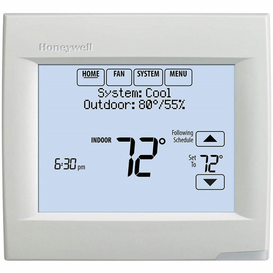
- Page 60 ® VISIONPRO 8000 WITH REDLINK™ OPERATION HOME. Touch to display Home screen. FAN. Select fan mode. SYSTEM. Select system mode (Heat/Cool). MENU. Touch to display options. Start here to set a program schedule. Current status. Shows system mode (heat/cool), outdoor temperature and humidity (with optional outdoor sensor).
-
Page 61: Setting The Time/Date
® VISIONPRO 8000 WITH REDLINK™ Setting the Time/Date 2. Touch On, Auto, Circ, or Follow Schedule. 3. Touch Done to save and exit. 1. Touch the current time. The screen displays Select Option. • On: Fan is always on. • Auto: Fan runs only when heating or cooling system is •... -
Page 62: Preset Energy-Saving Schedules
® VISIONPRO 8000 WITH REDLINK™ Preset Energy-Saving Schedules NOTE: To reduce costs, use the “Preset Energy-Saving Schedules” on page 62. These default Energy Saver settings can reduce expenses. 3. Select the days to schedule, touch Next. Table 3. Residential Use Default Schedule. Start Heat Cool... -
Page 63: Permanent Hold
® VISIONPRO 8000 WITH REDLINK™ Overriding Schedules: Residential 1. Touch to adjust the temperature (right side of screen) and the Hold Until time (left side). The schedule will resume when the Hold Until time expires. Temporary Hold Permanent Hold MCR34106 Fig. -
Page 64: Holiday Mode
® VISIONPRO 8000 WITH REDLINK™ Setting Vacation Hold: Residential 1. Touch MENU. This feature helps you save energy while you are away, and restores comfortable settings just before you return home. MCR34100 1. Touch MENU. Fig. 102. 2. Select Holiday Schedule. MCR34100 Holiday Schedule Fig. - Page 65 ® VISIONPRO 8000 WITH REDLINK™ 2. Select Create New Event. Add / Edit Holidays Create New Event MCR34119 MCR34116 Fig. 109. Fig. 106. 3. Touch the check box next to each holiday for which you 3. Select Specific Date or Month/Weekday. want to maintain specific settings, (Touch ...
- Page 66 ® VISIONPRO 8000 WITH REDLINK™ 1. Touch MENU. Press HERE Start Occupancy MCR34100 Fig. 112. 2. Select Holiday Mode to display Temperature While Away. Holiday Mode Equipment Status M34127 MCR34122 Fig. 115. Fig. 113. Touch the buttons to set the temperature or the Hold ...
- Page 67 ® VISIONPRO 8000 WITH REDLINK™ 2. Select Auto. stat was installed, the thermostat may maintain a 15% separation between humidification and dehu- midification settings. Adjusting Dehumidification Settings: Humidification Auto Residential Use This feature can control a dehumidifier or use your air conditioner to reduce humidity.
- Page 68 ® VISIONPRO 8000 WITH REDLINK™ Adjusting Dehumidification Settings: Adjusting Ventilation Settings Commercial Use 1. Touch MENU, and select Ventilation. This feature can control a dehumidifier or use your air conditioner to reduce humidity. 1. Touch MENU and select Dehumidification. MCR34100 Fig.
-
Page 69: Cleaning The Thermostat Screen
® VISIONPRO 8000 WITH REDLINK™ Temporary Boost: Touch 2. Select an option and follow prompts: to select how long to run ventilation temporarily. To turn it off, set it to zero. • Reminders to change filters • Fahrenheit/Celsius display •... -
Page 70: Adjusting Security Settings
® VISIONPRO 8000 WITH REDLINK™ 3. Touch Yes. A countdown timer displays elapsed time until • Unlocked: Full access allowed. • Partially locked: Only temperature can be changed. the screen is reactivated. • Fully locked: No access allowed. Clean screen Lock Mode for 30 seconds? Unlocked... -
Page 71: Advanced Features
® VISIONPRO 8000 WITH REDLINK™ Advanced Features P + I CONTROL A conventional mechanical or electronic thermostat does not control temperature precisely at setpoint. Typically there is an ADAPTIVE INTELLIGENT RECOVERY (RESIDENTIAL USE offset (droop) in the control point as the system load changes. ONLY) Many factors contribute to offset including the switch Over time, the VisionPRO®... - Page 72 ® VISIONPRO 8000 WITH REDLINK™ Depending on how your thermostat was installed, the thermostat Home screen will display humidity readings from only one sensor. Installer Options MCR33976 Fig. 149. Enter password 0 0 0 MCR33977 MCR3416 Humidity reading depends on location of sensor. Fig.
-
Page 73: Data Logs
® VISIONPRO 8000 WITH REDLINK™ Universal Input Options The Alerts Log contains information about the alert and system information. Indoor Air Sensor (ISU 500) • C7189U1005 (10K) The Alerts Log can include: • C7772A1004 (20K) • The alert name and description. •... -
Page 74: Dry Contact Alerts
® VISIONPRO 8000 WITH REDLINK™ Dry Contact Alerts Dirty Filter Alert When the dry contact device detects a dirty air filter (pressure A Dry Contact device such as a wet switch can be connected drop across the filter), the thermostat provides an alert to the to the S1, S2, S3 or S4 terminals at the Equipment Interface user to replace the filter. - Page 75 ® VISIONPRO 8000 WITH REDLINK™ ONE DRY CONTACT DEVICE ONE DRY CONTACT DEVICE MULTIPLE DRY CONTACT DEVICES MULTIPLE DRY CONTACT DEVICES ON ONE SET OF TERMINALS ON ONE SET OF TERMINALS Fig. 157. Wiring dry contact devices. 1. Wire the dry contact device to S1, S2, S3 or S4 terminals Refer to the instructions packed with the dry at the EIM.
-
Page 76: Staging Control
® VISIONPRO 8000 WITH REDLINK™ TO CHANGE DIFFERENTIAL SETTINGS 1. Select Advanced Options to view/adjust differentials between all stages. Scroll to see: Contact your dealer to service your sump pump Fig. 163. Fig. 162. 2. Default is Comfort. Adjust differentials as needed. 8. - Page 77 ® VISIONPRO 8000 WITH REDLINK™ Backup Heat Upstage Timer MANUAL TEMPERATURE CHANGE When the Backup Heat Droop is set to Comfort, the thermostat The Backup Heat Upstage Timer is available for any system uses backup heat as needed to keep the indoor temperature with 2 heating types and the Backup Heat Droop is set to 2 °F within 1 °F (0.5 °C) of the setpoint.
-
Page 78: Geothermal Radiant Heat
® VISIONPRO 8000 WITH REDLINK™ HEAT PUMP AND BACKUP HEAT OPERATION Heat pump with outdoor temperature lockouts Outdoor temperature lockouts are optional. See Installer Setup options (ISU 312). Alert Light - General with the Geothermal Radiant Heat followed by Geothermal Forced Air Heat and then Backup Heat as needed to maintain An alert light is located in the lower right corner of the the desired temperature. - Page 79 ® VISIONPRO 8000 WITH REDLINK™ Fossil Fuel Backup Heat (Backup Heat NOT 4. Select a Geothermal Forced Air Option. For example, if Geothermal Forced Air is used for both heating and cool- Allowed to Run with Heat Pump) ing, select the "Heating and Cooling" option. See Fig. 172.
-
Page 80: Indoor Air Quality (Iaq) Control
® VISIONPRO 8000 WITH REDLINK™ 7. Select the Backup Heat Type. See Fig. 175. humidity to help prevent frost or condensation on your windows. Use a higher number if indoor air seems too dry. To prevent frost/condensation on your windows during cold outdoor temperatures, poorly insulated windows require a lower Window Protection setting, which will limit how much your humidifier can run. - Page 81 ® VISIONPRO 8000 WITH REDLINK™ 2. If optional remote wireless indoor sensors are installed, 5. Select the system mode(s) to allow humidification. See you can choose which sensor you want to use for humid- Fig. 181. ification control. You can use a different sensor for dehu- NOTE: Heat includes Heat, Emergency Heat and Auto.
-
Page 82: Control Humidification Level
® VISIONPRO 8000 WITH REDLINK™ 2. Select Auto. Humidification Auto Fig. 182. 7. Set the desired lockout option. See Fig. 183. MCR34129 Fig. 186. 3. Touch to select humidity level. 4. Touch Done to save your settings. Touch Cancel to ignore changes. -
Page 83: Dehumidification - Residential
® VISIONPRO 8000 WITH REDLINK™ to operate in the same system mode (Heat, Cool, 1. Select the Dehumidification Equipment in ISU 900. See Off) and you are sensing humidity from two differ- Fig. 188. ent locations using a remote wireless indoor sen- sor, the thermostat will allow humidification and dehumidification to operate at the same time, and there is no deadband between humidification and... -
Page 84: Set Up Dehumidification With Whole House Dehumidifier
® VISIONPRO 8000 WITH REDLINK™ Set up Dehumidification With Whole House 4. Select the terminals wired to the A/C with Low Speed Fan. See Fig. 191. Dehumidifier Some screens shown in this section may not appear on the thermostat, depending on how you set up dehumidification. 1. - Page 85 ® VISIONPRO 8000 WITH REDLINK™ 4. Select the terminals wired to the Whole House Dehumid- ifier. See Fig. 197. Fig. 199. 7. Set the desired lockout option. See Fig. 200. Fig. 197. 5. Select the system mode(s) to allow dehumidification. See Fig.
-
Page 86: Set Up Dehumidification Away Mode
® VISIONPRO 8000 WITH REDLINK™ • Low Limit Temperature Setting If the cooling system is used to control humidity while Dehumidification Away Mode is active, the thermostat allows the cooling system to lower the indoor air to the Low Limit Temperature Setting to reach the Dehumidification Setting at ISU 920. -
Page 87: Control Dehumidification Level
® VISIONPRO 8000 WITH REDLINK™ Dehumidification - Commercial Control Dehumidification Level 1. Touch MENU and select Dehumidification. The thermostat reads the indoor humidity level and allows the user to set a dehumidification setting. The thermostat controls the humidity level using the cooling system or a dehumidifier. If humidification and dehumidification are setup to operate in MCR34100 the same system mode (Heat, Cool, Off) and you are sensing... -
Page 88: Set Up Dehumidification With Cooling System
® VISIONPRO 8000 WITH REDLINK™ Cooling Droop (ISU 908 and 910): This option uses the 2. If optional remote wireless indoor sensors are installed, cooling system to lower the temperature up to 5° F below the you can choose which sensor you want to use for dehu- current cool setpoint until the desired humidity is reached. -
Page 89: Set Up Dehumidification With Dehumidifier
® VISIONPRO 8000 WITH REDLINK™ 2. If optional remote wireless indoor sensors are installed, you can choose which sensor you want to use for dehu- midification control. For example, you can use one sen- sor for humidification control, and another for dehumidification. -
Page 90: Control Dehumidification Level
® VISIONPRO 8000 WITH REDLINK™ 5. Select the system mode(s) to allow dehumidification. 7. Set the desired lockout option. See Fig. 222. See Fig. 220. NOTE: Heat includes Heat, Emergency Heat and Auto. If the system is in Auto mode, the thermostat will allow dehumidification if the last call was for heat. -
Page 91: Ventilation
® VISIONPRO 8000 WITH REDLINK™ 2. Select Auto. • ASHRAE The thermostat operates ventilation equipment to meet the ASHRAE 62.2 ventilation standard based on CFM, number of bedrooms, and square footage of the house. ASHRAE 62.2 can only be met if the ventilation equipment is running. Dehumidification If the ventilation equipment is off for any reason (outdoor Auto... -
Page 92: Set Up Ventilation
® VISIONPRO 8000 WITH REDLINK™ 3. Select the Ventilation Control Method. See “Ventilation and ventilation is needed to meet ASHRAE. Lockouts can prevent ventilation during extreme weather conditions to keep Control Methods (ISU 1005)” on page 91 for more infor- humid, hot, and cold air out of the home. - Page 93 ® VISIONPRO 8000 WITH REDLINK™ will indicate the following based on the Equipment Venti- When using this option, it is recommended to lation Rate, Square Footage and Number of Bedrooms. increase the rate (CFM) of the ventilation equipment See Fig. 231. to meet the ASHRAE 62.2 ventilation standard in a •...
- Page 94 ® VISIONPRO 8000 WITH REDLINK™ 8. If Percent On Time was selected for ISU 1005, select the When ISU 1012 Ventilation Priority is set to Lockouts are Ventilation Percent on Time. See Fig. 233. Priority, or ISU 1005 Ventilation Control Methods is set to Percent On Time, the thermostat will indicate whether this meets or may not meet the ASHRAE 62.2 Standard or the Percent On Time setting.
- Page 95 ® VISIONPRO 8000 WITH REDLINK™ 2. Select Mode, Temporary Boost, or Lockout, then select or dehumidification. The thermostat will indicate whether this meets or may not meet the ASHRAE 62.2 Standard appropriate options. or the Percent On Time setting. See Fig. 237. NOTE: ISU 1014 Lockout Ventilation on Humidification or Dehumidification Calls is not an option when Mode...
-
Page 96: Iaq Reminders
® VISIONPRO 8000 WITH REDLINK™ 3. Select the reminder you want to set. 4. Press to set the timer length. Ranges, incre- ments, and units will change based on the reminder. Lockout in Sleep NOTE: When set for run time days, the thermostat Period: tracks the amount of time the fan has run and compares that time against the number of run... - Page 97 ® VISIONPRO 8000 WITH REDLINK™ 4. Press the up or down arrows to set the outdoor tempera- You can change or create custom reminders in ISU 1200. ture and press Next. Fig. 248. Fig. 251. For example, to set up a Fall Service Reminder based on NOTE: A seasonal maintenance reminder will appear Outdoor Temperature: when the outdoor temperature reaches the level...
- Page 98 ® VISIONPRO 8000 WITH REDLINK™ 7. When the user touches Press HERE for info on the 10. To clear the Alert, (and turn off the Red Alert Light on the Home Screen, the reminder message will be displayed. thermostat), select Dismiss. To create a new custom reminder: 1.
- Page 99 ® VISIONPRO 8000 WITH REDLINK™ 5. Touch Press HERE to edit to set the reminder message 8. Select whether you want the reminder to appear only (see Fig. 260). once or to be recurring, and press Next. Fig. 260. Fig. 263. 6.
-
Page 100: Microsd Card
VisionPRO® thermostat using the microSD port. 1. In a web browser on your computer, go to http://thermostatsetup.honeywell.com 2. Connect a microSD card to a USB adapter. Then con- nect the USB adapter to your computer. Computer Fig. - Page 101 ® VISIONPRO 8000 WITH REDLINK™ 6. When the Save As box opens, navigate to the directory 3. Follow the prompts on the screen. of your USB device and save the file. For example, if your • To add information from the card to the thermostat, USB drive is letter “F,”...
-
Page 102: Commercial Features
® VISIONPRO 8000 WITH REDLINK™ COMMERCIAL FEATURES The thermostat can be setup for residential or light commercial applications (ISU 101). When the thermostat is setup for commercial, the thermostat meets commercial code, Title 24 and provides the following features: • Commercial language (occupied and unoccupied) •... - Page 103 ® VISIONPRO 8000 WITH REDLINK™ 4. Make selections as prompted on each screen. For more 4. Review the settings and touch Done to save them. Touch information, see next two pages. Cancel to ignore the changes. 5. Touch Done to save your settings. Setting Custom Events: Commercial Schedule adjusted to 62 in heating...
- Page 104 ® VISIONPRO 8000 WITH REDLINK™ 4. Touch to select the Heat and Cool temperatures. Temperature Temperature While Away During Holiday MCR34123 MCR34121 Fig. 287. Fig. 284. 4. Review the settings and touch Done to save them. Touch 5. Review the settings and touch Done to save them. Touch Cancel to ignore the changes.
-
Page 105: Ramp Rates (Commercial Use)
® VISIONPRO 8000 WITH REDLINK™ Ramp Rates (Commercial Use) Remote Setback (Commercial Use) When the ramp rate is set to Off, the thermostat begins The thermostat allows you to do REMOTE SETBACK when set recovery at the scheduled time. up for commercial use. This feature requires an occupancy sensor connected to the S1, S2, S3 or S4 terminals at the When a ramp rate is set, recovery begins early to reach the Equipment Interface Module. -
Page 106: Economizer And Time Of Day (Tod) Operation
® VISIONPRO 8000 WITH REDLINK™ 3. Select Normally Open when Occupied or Normally Closed when Occupied based on the type of dry contact device installed. NOTE: Normally Open when Occupied: The Dry Contact device is open when the room is occu- pied and will close when the room is unoccu- pied. -
Page 107: Pre-Occupancy Purge
® VISIONPRO 8000 WITH REDLINK™ Time of Day (TOD) The thermostat can be set up for a Time of Day output in the installer setup. This output is commonly used to control lighting panels, turning them on for occupied periods and off for unoccupied periods. -
Page 108: Battery Replacement
® VISIONPRO 8000 WITH REDLINK™ Battery Replacement Thermostat Portable Comfort Control Install fresh batteries when the REPLACE BATTERY warning begins flashing. The warning flashes about 60 days before batteries are depleted. SET TO REPLACE BATTERY Replace Batteries Press HERE for info M28896 MCR28475 Install fresh batteries when the REPLACE BATTERY warning... - Page 109 ® VISIONPRO 8000 WITH REDLINK™ Wireless Indoor Sensor Replace batteries in your indoor sensor when a warning appears on the thermostat screen, about 60 days before batteries are depleted. When the sensor status light begins flashing red, battery power is critically low and will be depleted within 2–3 weeks. During normal operation, the status light remains off.
-
Page 110: Optional Accessories
The thermostat can be used with up to 6 Wireless Indoor Sensors. REDLINK™ INTERNET GATEWAY The Honeywell RedLINK Internet Gateway gives you remote access to your VisionPRO® thermostat from the web, smart phone or tablet. You can view or adjust indoor temperature, system mode and other settings. -
Page 111: Heat Pump And Backup Heat Operation 78 Portable Comfort Control
® VISIONPRO 8000 WITH REDLINK™ PORTABLE COMFORT CONTROL The Portable Comfort Control communicates wirelessly with the thermostat, and can control up to 16 thermostats. NOTE: Each thermostat can only be connected to 1 Portable Comfort Control. If you have one thermostat, you move this remote control from Fig. -
Page 112: Remote Indoor Sensors
® VISIONPRO 8000 WITH REDLINK™ REMOTE INDOOR SENSORS appropriate sensor for Humidification Control in the Installer Setup. For example, in Fig. 306, the MAIN LEVEL remote indoor sensor is selected for Humidification Control. For installation, see “C7189R1004 Wireless Indoor Sensor” on page 59, and “C7189U1005 Wired Indoor Sensor”... -
Page 113: Temperature Display
® VISIONPRO 8000 WITH REDLINK™ Wireless Indoor Sensor Battery level indicators (during use) • Good: Status light remains off. • Low: Battery power will be depleted in about 2 months. Thermostat displays Low Battery warning. Status light remains off. • Critical: Battery power will be depleted in about 2–3 weeks. Status light flashes red. -
Page 114: Humidity Display
® VISIONPRO 8000 WITH REDLINK™ Humidity Display If you are sensing Humidity from one location (internal or remote), the humidity reading displayed on the home screen is from the sensor that is being used for control. In Fig. 309, the humidity reading is from the remote indoor sensor. Fig. - Page 115 ® VISIONPRO 8000 WITH REDLINK™ Calibration - Outdoor Sensor Table 7. C7089U1006 Sensor Resistance at Outdoor Temperature. (Continued) The C7089U1006 Outdoor Sensor is calibrated at the factory Outdoor Outdoor and cannot be recalibrated in the field. Temperature Temperature Ohms of Ohms of Table 7.
- Page 116 ® VISIONPRO 8000 WITH REDLINK™ Backup Control 2. Press REMOVE, then YES to disconnect from the old thermostats. This section explains when backup control is used. For 3. To reconnect the thermostat, go to “Linking RedLINK example, if batteries in the wireless indoor sensors are Accessories”...
-
Page 117: Wiring
® VISIONPRO 8000 WITH REDLINK™ WIRING See Table 9 for Equipment Interface Module terminal descriptions and Table 10 for thermostat terminal descriptions. Table 9. Equipment Interface Module Terminal Designation Descriptions. Conventional System Heat Pump Terminal Description Terminal Description Common wire from 24 VAC transformer. Common wire from 24 VAC transformer. - Page 118 ® VISIONPRO 8000 WITH REDLINK™ Table 10. Thermostat Terminal Designation Descriptions. Conventional System Heat Pump Terminal Description Terminal Description Common wire from secondary side of cooling Common wire from secondary side of cooling transformer (if 2 transformers). transformer. Cooling power Cooling power Heating power Heating power...
- Page 119 ® VISIONPRO 8000 WITH REDLINK™ Table 11. Wiring Diagrams by System Type. CONVENTIONAL Wiring Diagram System Type Reference Standard Heat/Cool Heat Pump with Auxiliary Heat Geothermal radiant heat Heat pump with oil forced air backup. Geothermal radiant heat with geothermal forced air and backup heat using separate transformer for the radiant heat Wood stove-fired hot water fan coil with...
-
Page 120: Eim Wiring Diagrams
® VISIONPRO 8000 WITH REDLINK™ EIM Wiring Diagrams Typical wiring of a conventional system with up to 3-stage heat and 2-stage cool with one transformer. FURNACE TRANSFORMER TO THERMOSTAT HEAT STAGE 1 CONV POWER HEAT STAGE 2 HEAT COOL HEAT STAGE 3 STATUS LEDS COMPRESSOR... - Page 121 ® VISIONPRO 8000 WITH REDLINK™ Typical wiring of a heat pump system with up to four-stage heat and two-stage cool with one transformer. TO THERMOSTAT CHANGEOVER VALVE HEAT PUMP BACKUP HEAT POWER STAGE 1 AUX1 HEAT AUX1 AUX2 BACKUP HEAT COOL AUX2 STAGE 2...
- Page 122 ® VISIONPRO 8000 WITH REDLINK™ Typical wiring for geothermal radiant heat, geothermal forced-air, and backup heat with one transformer. TO THERMOSTAT CHANGEOVER VALVE HEAT PUMP BACKUP HEAT POWER STAGE 1 AUX1 HEAT AUX1 BACKUP HEAT AUX2 COOL AUX2 STAGE 2 STATUS LEDS COMPRESSOR...
- Page 123 ® VISIONPRO 8000 WITH REDLINK™ ZONE VALVE BOILER THERMOSTAT/EIM TO THERMOSTAT TRANSFORMER HEAT PUMP HEAT PUMP W W2 W3 Y Y2 G A AUX1 THERMOSTAT/EIM AUX2 RELAY OIL FURNACE R IS JUMPERED TO RH. THE BOILER CONTROLS THE CIRCULATOR PUMP IN THIS SYSTEM. M31477 Fig.
-
Page 124: Geothermal Radiant Heat Diagram
® VISIONPRO 8000 WITH REDLINK™ THERMOSTAT/EIM TO THERMOSTAT FURNACE HEAT PUMP HEAT PUMP AUX1 AUX2 PUMP RADIANT HEAT ZONE MODULE VALVE TRANSFORMER M34525 Fig. 321. Geothermal radiant heat with geothermal forced air and backup heat using separate transformer for the radiant heat. - Page 125 ® VISIONPRO 8000 WITH REDLINK™ THERMOSTAT/EIM THERMOSTAT/EIM TO THERMOSTAT TO THERMOSTAT CONV CONV FURNACE FURNACE RELAY BOILER THE BOILER IS CONTROLLING THE CIRCULATOR PUMP CONFIGURE THE THERMOSTAT TO ENERGIZE THE FAN IN THIS DIAGRAM. WITH A CALL FOR HEAT. M31483 THE THERMOSTAT WILL ENERGIZE ONLY THE FAN WITH A CALL FOR STAGE 1 HEAT.
- Page 126 ® VISIONPRO 8000 WITH REDLINK™ THERMOSTAT/EIM TO THERMOSTAT CONV ZONE VALVE ZONE 1 RELAY BOILER TRANSFORMER HZ311, HZ322, OR HZ432 ZONE PANELS COULD BE USED TO CONTROL A FORCED AIR FURNACE ZONED WITH DAMPERS. THE BOILER IS CONTROLLING THE CIRCULATOR PUMP IN THIS DIAGRAM. M34526 Fig.
- Page 127 ® VISIONPRO 8000 WITH REDLINK™ THERMOSTAT/EIM THERMOSTAT/EIM TO THERMOSTAT TO THERMOSTAT CONV CONV ZONE 1 RELAY FURNACE RELAY BOILER ZONE 1 HOT WATER RELAY PANEL HZ311, HZ322, OR HZ432 ZONE PANELS COULD BE USED TO CONFIGURE THE THERMOSTAT TO ENERGIZE THE FAN CONTROL A FORCED AIR FURNACE ZONED WITH DAMPERS.
- Page 128 ® VISIONPRO 8000 WITH REDLINK™ THERMOSTAT/EIM TO THERMOSTAT AIR HANDLER HEAT PUMP HEAT PUMP AUX1 AUX2 M31487 Wood stove with heat pump and backup electric strips. (For applications in which the thermostat only needs to run the blower fan when stove is hot). 1 Select Geothermal Radiant Heat at ISU 201.
-
Page 129: Wiring Iaq Equipment Or A Heat/Cool Stage To The Universal Terminals
® VISIONPRO 8000 WITH REDLINK™ Wiring IAQ Equipment or a Heat/Cool Stage to the Universal Terminals To Thermostat “U” terminals can be used for humidification, dehumidification, ventilation or a stage of heating/cooling. SYSTEM SYSTEM TRANSFORMER TRANSFORMER THERMOSTAT THERMOSTAT HUM, DEHUM OR FIELD INSTALL JUMPER VENT BETWEEN R AND U1... - Page 130 ® VISIONPRO 8000 WITH REDLINK™ Wiring IAQ Equipment or a Heat/Cool Stage to the Universal Terminals To Equipment Interface Module “U” terminals can be used for humidification, dehumidification, ventilation or a stage of heating/cooling. NON-POWERED HUMIDFIER POWERED FIELD INSTALLED HUMIDIFIER JUMPER BETWEEN R AND U1 24 VAC...
- Page 131 ® VISIONPRO 8000 WITH REDLINK™ HEAT STAGE 3, COOL STAGE 3, COOL STAGE 4 OR GEOTHERMAL RADIANT HEAT TRANSFORMER Fig. 337. Connecting a stage of heating or cooling to a universal relay (U1, U2, U3). 1 U1, U2, and U3 are normally open dry contacts when set up for a stage of heating or cooling. 2 You must install a field jumper if the stage of heating or cooling is powered by the system transformer.
-
Page 132: Economizer Module Wiring Diagrams
® VISIONPRO 8000 WITH REDLINK™ Economizer Module Wiring Diagrams Typical wiring of a W7220 Economizer Module for a heat pump system, using a VisionPRO with RedLINK thermostat or Equipment Interface Module. Rooftop Unit AUX AUX 2 W7220 Economizer Module (See wiring guidelines provided with the product) AUX2-I E-GND AUX1-O... - Page 133 ® VISIONPRO 8000 WITH REDLINK™ Typical wiring of a W7213/W7214 Economizer Module for a heat pump system, using a VisionPRO with RedLINK thermostat or Equipment Interface Module. Rooftop Unit AUX AUX 2 W7213/W7214 Economizer Module (See wiring guidelines provided with the product) O OR B 2 &...
-
Page 134: Wiring C7089U1006 Outdoor Sensor
® VISIONPRO 8000 WITH REDLINK™ Wiring C7089U1006 Outdoor Sensor Wiring must comply with applicable codes, ordinances and regulations: 1. Wire C7089U1006 Outdoor Sensor to S terminals on the CAUTION thermostat or EIM. If leadwire provided is not long Electrical Interference (Noise) Hazard. enough (60 in.), run a cable to a hole at C7089U1006 Can cause erratic system operation. -
Page 135: Wiring Guide - Wired Indoor Sensors
® VISIONPRO 8000 WITH REDLINK™ Wiring guide — Wired Indoor Sensors Wiring 2 TR21 sensors (20k ohm) and 1 TR21-A sensor (10k CAUTION ohm) for temperature averaging network. Select 20K in the Installer Setup (ISU 503) when using 2 TR21 sensors and 1 Electrical Interference (Noise) Hazard. - Page 136 ® VISIONPRO 8000 WITH REDLINK™ ZONING The following diagrams show the wiring for zoning with different IAQ equipment. W1/E FURNACE W1/E DS/BK TRANSFORMER C7735A1000 DATS DATS DATS THM4000R POWER WIRELESS SETUP CONNECTED CONNECT THM4000R1000 VISIONPRO THERMOSTATS CAN BE POWERED BY ANY TRANSFORMER. IN THIS EXAMPLE THEY ARE POWERED BY THE SAME TRANSFORMER THAT POWERS THE HZ432.
- Page 137 Select the terminals wired to the humidifier at ISU 803 (U1, U2, U3). In Fig. 348, the humidifier is wired to U1. To humidify in all zones, set ISU 807 Humidifier Control to “Hum Controls Fan.” Call Honeywell zoning at 1-800-828-8367 if you need assistance with the zoning controls.
- Page 138 ® VISIONPRO 8000 WITH REDLINK™ Zoning and Ventilation TrueZONE PANEL FURNACE W1/E VisionPRO ERV/HRV DS/BK INTERLOCK B AUX W SELECT THE TERMINALS WIRED TO THE VENTILATOR AT ISU 1002 (U1, U2, U3). TO VENTILATE IN ALL ZONES, SET ISU 1006 VENT FAN CONTROL TO EQUIP CONTROLS FAN.
- Page 139 ® VISIONPRO 8000 WITH REDLINK™ Zoning FAQs Q: How does the RedLINK VisionPRO thermostat control a humidifier in zoned systems? A: If ISU 807 Humidifier Control is set to Tstat Controls Fan, then the zone panel will close the dampers for the other zones with a call for humidification.
-
Page 140: Troubleshooting
• Increase the separation between the equipment and device. receiver. Automation and Control Solutions Honeywell International Inc. 1985 Douglas Drive North ® U.S. Registered Trademark Golden Valley, MN 55422 © 2013 Honeywell International Inc. 68-0312—03 M.S. Rev. 11-13 customer.honeywell.com Printed in United States...
Need help?
Do you have a question about the TH8320R1003 and is the answer not in the manual?
Questions and answers
I have a 2 zone system. When both are calling for heat the heat pump eventually locks up and shuts down.Therms. are new TH8320R1003
A Honeywell TH8320R1003 thermostat could lock up and shut down in a 2 zone heating system when both zones are calling for heat due to an erratic temperature indication system. This erratic behavior can trigger the 5-minute compressor timing delay, which may cause the thermostat to lock up. Additionally, if a dry contact device (such as a sail switch) detects no airflow for 5 minutes after a call for heat, the thermostat may shut down and lock out heating to protect the system.
This answer is automatically generated
Why does the red alert light blink three times
I have replaced the CR2032 battery as requested by system msg but msg still appears.
If the "Replace battery" message still appears after replacing the CR2032 battery in the Honeywell TH8320R1003 thermostat, ensure that all required batteries, including the AA batteries, have also been replaced with fresh ones. If all batteries are replaced and the message remains, try removing the thermostat from the wall plate and reattaching it to reset the system. The message should clear if the system detects proper battery status.
This answer is automatically generated
How do I program from Monday thru Sunday to come on the same time every day?
can I use lithium batteries instead of alkaline