Sign In
Upload
Manuals
Brands
New Holland Manuals
Compact Loader
LS140
New Holland LS140 Manuals
Manuals and User Guides for New Holland LS140. We have
2
New Holland LS140 manuals available for free PDF download: Workshop Manual, Repair Manual
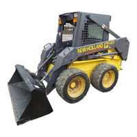
New Holland LS140 Workshop Manual (671 pages)
Brand:
New Holland
| Category:
Compact Loader
| Size: 9.85 MB
Table of Contents
Section 00 - General Information
2
Table of Contents
2
Introduction
3
About Improvements
3
Company Policy
4
Parts and Accessories
4
Model Codes
4
Precautionary Statements
5
Safety Precaution Information
6
General Safety Information
8
Machine Model and Serial Number Location
10
Engine Model and Serial Number Location
10
Installation of Adjustable Fittings in Straight Thread O Ring Bosses
13
Standard Torque Data for Hydraulic Tubes and Fittings
13
Pipe Thread Fitting Torque
14
Lubricants and Coolants
14
Sealants
14
Raising Boom Without Hydraulic Oil Flow
15
Properly Support Boom on Boom Lock Pins
15
Properly Support a Raised Machine
15
Raising Boom Without Battery Voltage (12V)
16
Reattaching Cylinders after Repair with Boom Resting on Boom Lock Pins
18
Major Unit Overhaul
19
Cab and Boom Tilt Procedure
20
Craning the Skid Steer
27
Special Tools
30
Specifications
31
Dimensions
34
Table of Contents
36
Engine Component Descriptions
38
General Description
38
General Engine Information
38
Engine Model and Serial Number Location
40
Safety Precautions
41
General Engine Specifications
42
Troubleshooting
44
Specifications - Service Standards
47
Torque Specifications
52
Engine Components Electrical Diagram
53
Engine Removal
54
Engine Disassembly Sequence
60
Engine Component Maintenance
68
Valve Seat
71
Cylinder Block
74
Piston and Piston Rings
75
Connecting Rod
79
Bearing Holder
83
Front Crankshaft Bearing (Bushing)
85
Crankshaft
87
Flywheel and Ring Gear
89
Camshaft Assembly
90
Camshaft Gear and Bearing Assembly
90
Oil Pump
91
Timing Gear
91
Port Block
92
Oil Filter
93
Thermostat
94
Water Pump Assembly and Thermostat Housing
94
Governor
95
Governor Operation
96
Engine Reassembly Sequence
98
Crankshaft and Bearing Holder Assembly
99
Backplate/Flywheel Housing
100
Flywheel
100
Rear Oil Seal
100
Dipstick and Tube
101
Oil Sump
101
Piston and Connecting Rod
101
Front Plate
102
Idler Gear and Oil Pump Assembly
102
Timing Gear Case Installation
103
Crankshaft Pulley
104
Injection Pump Installation
104
Spill Timing Procedure
105
Reinstallation of Engine into Skid Steer Frame
114
How to Operate the Engine after Overhaul
116
Cooling System Operation
117
Water Pump Assembly and Thermostat Housing
118
Radiator
120
Diesel Fuel
121
Diesel Fuel Storage
121
Fuel Specifications
121
Fuel System Components
121
Fuel Guage
123
Cold Start Aid
124
Fuel Filter System
124
Priming the Fuel System
125
Fuel System Testing
126
Fuel System Components
129
Fuel Injection Timing
137
Miscellaneous Engine Electrical
140
Special Tools
142
Labor Guide
143
Section 29 - Hydrostatic Transmission Chapter 1 - Neutralizer, Pumps, Motors
146
General Information
148
Operation
148
Specifications
150
Troubleshooting
151
Hydrostatic Drive System Testing
153
Hydrostatic System Oil Flow
156
Hydrostatic Charge System Pressure Test
159
Hydrostatic Pump Case Drain Test
161
Hydrostatic Pump High Pressure Test
164
Hydrostatic Pump Efficiency Test
166
Hydrostatic Motor Case Drain Test
168
Hydrostatic Motor Efficiency Test
169
Hydraulic, Hydrostatic System Air Ingress Test
171
Hydrostatic Pumps
172
Hydrostatic Motor
193
Hydraulic System Cleaning Procedure
211
Start-Up Procedure after Rebuild (after Pump or Motor Replacement)
214
Charge Check Valve
216
Hydrostatic System Controls
218
Steering System
218
Neutralizer Assembly
220
Left Control Handle with no Boom Control
226
Left Control Handle with Boom Control
229
Right Control Handle with Auxiliary or Bucket Control
235
Drive Control Adjustment Procedure
244
Neutral Adjustment
245
Labor Guide
247
Section 33 - Brakes and Controls Chapter 1 - Parking Brake
248
General Information
249
Specifications
251
Troubleshooting
252
Parking Brake
254
Testing
254
Section 35 - Hydraulic System Chapter 1 - Valves, Gear Pump, Cylinders, and Pedal Controls
270
Hydraulic System Compatibility
273
Boom Cylinder Pivot Pin Location and Machine Usage
275
Boom Cylinder Pivot Pins
275
Control Valve Power Beyond
276
Specifications
277
Troubleshooting
279
Auxiliary Boom Hydraulics Troubleshooting
283
Hydraulic System Testing
285
Hydraulic System Oil Flow (Neutral Position)
291
Control Valve - Bucket Spool Shifted
292
Control Valve - Boom Spool Shifted
293
Control Valve - Auxiliary Spool Shifted
294
Main System Pressure Tests
295
Checking Main System Pressure at Boom Cylinders
298
Checking Main System Pressure at Bucket Cylinders
299
Checking Main System Pressure at Auxiliary Boom Hydraulic Quick Couplers
300
Boom Circuit Relief Valve Test
301
Gear Pump Flow Efficiency Test
303
Boom and Bucket Spool Lock Solenoid Test
307
Hydraulic, Hydrostatic System Air Ingress Test
309
Hydraulic Pump Installation
323
Cylinders, Boom and Bucket
333
Boom Cylinder Disassembly
334
Boom Cylinder Reassembly
334
Boom Cylinder Reinstallation
334
Boom Cylinder Removal
334
Bucket Cylinder Disassembly
341
Bucket Cylinder Reassembly
341
Bucket Cylinder Reinstallation
341
Bucket Cylinder Removal
341
Pedal Controls
345
Pedal Inspection (with Boom and Bucket Pedal Controls)
345
Pedal Reinstallation (with Boom and Bucket Pedal Controls)
347
PEDAL REMOVAL with Boom and Bucket Hand Controls
350
Pedal Inspection (with Boom and Bucket Hand Controls)
351
PEDAL REINSTALLATION with Boom and Bucket Hand Controls
352
Hydraulic Cooling, Filter, Reservoir System
355
Base Removal
356
Filter Removal
356
Filter System
356
Oil Cooler
357
Oil Cooler Removal
357
Reassembly
357
Oil Reservoir
359
Oil Reservoir Removal
360
Labor Guide
362
Section 44 - Axles and Wheels Chapter 1 - Axles
384
General Information
385
Specifications
387
Troubleshooting
388
Testing
390
Axle Housing Assembly Removal
391
Axles
391
Final Drive
399
Tires/Wheels
413
Tire and Track Installation
414
Loader Boom Stop Adjustment
415
Labor Guide
417
Section 55 - Electrical System Chapter 1 - Advanced Warning System, Circuits, Alternator, and Starter
426
General Electrical Information
431
Definition of Terms
432
Adapting Attachments Requiring 12V Electrical Power
434
Specifications
437
Electrical Diagram
440
Advanced Warning System
444
Electronic Instrument Cluster (EIC)
444
(EIC) Electronic Instrument Cluster Front Panel
445
EIC Functional Groups
446
Automatic Shutdown
451
Engine Preheat
451
Operating Mode
452
Broken Alternator/Water Pump Belt Warning
454
EIC Interlocks
455
Fuel Level
455
EIC Lock Mode
456
EIC Engine Preheat
457
Troubleshooting
458
Advanced Warning System (AWS)
461
EIC Board Self Test
462
Diagnostic and Setup Modes
463
Arrow, Open Book, and Audible Alarm Test
465
Diagnostic Mode EIC Circuit Tests
465
EIC Setup Mode
469
Blown Fuse Symptom and Testing
477
Electronic Instrument Cluster (EIC) and Starter Circuits
477
Testing Other EIC Functions
479
EIC Board Reading Accuracy
482
EIC Board Claims Warranty
484
Electrical Circuits
485
Seat Switch Circuit to EIC Board
486
Seat Belt Switch Circuit to EIC Board
487
Hydraulic Oil Filter Restriction Switch Removal
531
Hydraulic Oil Temperature Sender Installation
531
Hydraulic Oil Temperature Sender Removal
531
Boom/Bucket Control Valve Spool Lock Solenoids
533
Boom/Bucket Control Valve Spool Lock Solenoids Installation
533
Boom/Bucket Control Valve Spool Lock Solenoids Removal
533
Main Wire Harness Removal
534
Wire Harness
534
Main Wire Harness Installation
539
Road/Work Lights
543
Alternator (40 Amp Version)
547
Charging Circuit
547
Alternator Service Specifications
549
Alternator System Testing and Troubleshooting
550
Initial Tests
553
Service Precautions
553
Alternator Reinstallation
565
Starter
566
Starter Motor Troubleshooting
566
Starter Motor Disassembly
568
Starter Motor Removal
568
Starter Reinstallation
586
Glow Plug
587
Glow Plug Troubleshooting
587
Miscellaneous Engine Components
587
Fuel Shut-Off Solenoid
588
Oil Pressure Switch
588
Labor Guide
589
Section 82 - Front Loader (Boom and Mounting Plate) Chapter 1 - Buckets
590
Buckets
591
General Information
591
Boom
592
Boom Lock Pins and Linkage
592
Attachment Mounting Plate
593
Boom and Cylinder Pivot Pin Location and Machine Usage
594
Boom and Cylinder Pivot Pins
594
Pallet Fork
596
Utility Fork
597
Bucket Latch Plate Installation Procedure
599
Dirt Tooth Kit Installation
602
Bucket Tooth Spacing
603
Boom Lock Pin/Linkage
605
Boom, Upper and Lower Link
608
Front Boom Mounting Plate Pivot Hub Replacement
614
Boom, Upper and Lower Link Reinstallation
616
Attachment Mounting Plate
621
Latch Lever and Pin Removal/Repair
621
Repair/Rebuild Mounting Plate
621
Checking Procedure for Buckets and Attachments
627
Checking Procedure
629
Checking the Loader Faceplate
630
Labor Guide
632
Section 88 - Accessories Chapter 1 - Dealer Installed Options
634
Adapting Attachments Requiring 12V Electrical Power
635
General Information
635
Hydraulic System Compatibility
638
Arm Pads for Cab Side Panels
640
Armrests for Deluxe Seat
641
Forearm Rests
642
Back-Up Alarm
643
Block Heater (Engine)
644
Electric Power Supply (12 Volt, 15 Amp)
645
Aspirator Precleaner Muffler
646
Exhaust (Engine)
646
Horn
648
Shoulder Belt (Seat)
649
Slow-Moving Vehicle (SMV) Sign Kit
650
Warning Light (Rotary Beacon)
651
Warning Lights (Four-Way Flashers/Turn Signal/Horn)
654
Labor Guide
658
General Information
661
Seat and Seat Pan Support
661
Seat Pan Support Removal
663
Seat Removal
663
Seat, Switch and Pan Reinstallation
665
Safety Decals
667
Labor Guide
670
Advertisement
New Holland LS140 Repair Manual (41 pages)
Brand:
New Holland
| Category:
Compact Loader
| Size: 0.52 MB
Table of Contents
Table of Contents
25
Introduction
26
About Improvements
26
Company Policy
27
Parts and Accessories
27
Model Codes
27
Precautionary Statements
28
Safety Precaution Information
29
General Safety Information
31
Machine Model and Serial Number Location
33
Engine Model and Serial Number Location
33
Installation of Adjustable Fittings in Straight Thread O Ring Bosses
36
Standard Torque Data for Hydraulic Tubes and Fittings
36
Pipe Thread Fitting Torque
37
Lubricants and Coolants
37
Sealants
37
Properly Support a Raised Machine
38
Properly Support Boom on Boom Lock Pins
38
Raising Boom Without Hydraulic Oil Flow
38
Raising Boom Without Battery Voltage (12V)
39
Advertisement
Related Products
New Holland LS120
New Holland LS125
New Holland LS180
New Holland LS190
New Holland LS150
New Holland Super Boom L190
New Holland L225
New Holland L230
New Holland L216 Tier 4
New Holland L315 Tier 3
New Holland Categories
Tractor
Farm Equipment
Excavators
Compact Loader
Lawn and Garden Equipment
More New Holland Manuals
Login
Sign In
OR
Sign in with Facebook
Sign in with Google
Upload manual
Upload from disk
Upload from URL