Sign In
Upload
Manuals
Brands
Delta Electronics Manuals
DC Drives
ASDA-B Series
Delta Electronics ASDA-B Series Manuals
Manuals and User Guides for Delta Electronics ASDA-B Series. We have
1
Delta Electronics ASDA-B Series manual available for free PDF download: User Manual
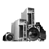
Delta Electronics ASDA-B Series User Manual (322 pages)
ASDA-B Series Standard AC Servo Drive for General Purpose Applications
Brand:
Delta Electronics
| Category:
DC Drives
| Size: 7.98 MB
Table of Contents
Installation
4
Operation
4
Unpacking Check
4
Wiring
4
Main Circuit Terminal Wiring
5
Table of Contents
6
Technical Support and Service
12
User Information
12
Chapter 1 Unpacking Check and Model Explanation
14
Unpacking Check
14
Delta AC Servo Drive and Motor
15
Model Explanation
16
Nameplate Information
16
Serial Number Explanation
16
Model Name Explanation
17
ECMA Series Servo Motor
18
Servo Drive and Servo Motor Combinations
19
Servo Drive Features
20
Control Modes of Servo Drive
21
Installation Notes
22
Storage Conditions
22
Chapter 2 Installation and Storage
22
Installation Conditions
23
Installation Procedure and Minimum Clearances
24
Drive Mounting
24
Minimum Clearances
24
Motor Mounting
24
Side by Side Installation
25
Connecting to Peripheral Devices
26
Connections and Wiring
26
Chapter 3 Connections and Wiring
26
Servo Drive Connectors and Terminals
27
Wiring Notes
28
Wiring Methods
29
Single-Phase Power Supply Connection
29
Three-Phase Power Supply Connection
30
Motor Power Cable Connector Specifications
30
Encoder Connector Specifications
32
Cable Specifications for Servo Drive and Servo Motor
33
Basic Wiring
34
Basic Wiring Schematic of 750W Models
35
Basic Wiring Schematic of 1Kw and above Models
36
Input / Output Interface Connector -CN1
37
CN1 Terminal Identification
37
The Layout of CN1 Drive Connector
37
CN1 Terminal Signal Identification
37
Signals Explanation of Connector CN1
38
General Signals
38
B DO Signals
39
DI Signals
40
D Source of Speed Command
41
E Source of Torque Command
41
Default DI Signals and DO Signals
42
User-Defined DI and DO Signals
43
Setting of Parameter P2-10 to P2-15
44
Setting of Parameter P2-18 to P2-20
44
Wiring Diagrams of I/O Signals (CN1)
45
C1: Speed / Torque Analog Signal Input
45
C2-1: Pulse Input (Open Collector – Internal Power)
46
C2-2: Pulse Input (Open Collector – External Power)
46
C3: Pulse Input (Line Driver)
47
Wiring of DO Signal, for Use of Internal Power Supply, General Load
47
Encoder Connector CN2
49
The Layout of CN2 Drive Connector
49
CN2 Terminal Signal Identification
49
Serial Communication Connector CN3
50
CN3 Terminal Layout and Identification
50
The Layout of CN3 Drive Connector
50
Connection between Pc/Keypad and Connector CN3
51
Connection between Keypad and CN3
51
Standard Connection Example
52
Position Control Mode
52
Speed Control Mode
53
Torque Control Mode
54
Description of Digital Keypad ASD-PU-01A
56
Chapter 4 Display and Operation
56
Display Flowchart
58
Monitor Mode, Parameter Mode and Parameter Setting Mode
58
SAVE Mode (Save Parameter Settings from the Drive to the Keypad)
59
WRITE Mode (Parameter Settings Written out from Keypad to the Drive)
60
Fast Edit Mode (Fast Editing, Static & Dynamic Auto-Tuning)
61
Status Display
63
Save Setting Display
63
Abort Setting Display
63
Fault Message Display
63
Monitor Setting Display
64
Fault Code Display Operation
66
Fault Code History
66
Current Display Fault Code History
66
JOG Operation
67
DO Force Output Diagnosis Operation
69
DI Diagnosis Operation
70
DO Diagnosis Operation
70
Parameters Read and Write
71
Description of Digital Keypad ASD-PU-01B
73
Display Flowchart
74
SAVE Mode
76
WRITE Mode
78
Fast Edit Mode
80
Dynamic Auto-Tuning Mode
81
Static Auto-Tuning Mode
82
Polarity Setting Display
83
Status Display
83
Fault Code Display Operation
86
JOG Operation
86
DO Force Output Diagnosis Operation
88
DI Diagnosis Operation
89
DO Diagnosis Operation
90
Parameters Read and Write
91
Inspection Without Load
94
Chapter 5 Trial Run and Tuning Procedure
94
Applying Power to the Drive
96
Main Circuit Wiring
96
Turn the Power on
96
Over Voltage
96
Encoder Error
97
Emergency Stop Activated
97
Reverse Limit Switch Error
97
Forward Limit Switch Error
98
Overcurrent
98
Undervoltage
98
Magnetic Field Error
99
Input Power Phase Loss
99
JOG Trial Run Without Load
100
ASD-PU-01A Tuning Flowchart
100
ASD-PU-01B Tuning Flowchart
101
Speed Trial Run Without Load
102
Tuning Procedure
104
Tuning Flowchart
106
Load Inertia Estimation Flowchart
107
Automode (PI) Tuning Flowchart
108
Automode (PDFF) Tuning Flowchart
110
Limit of Load Inertia Estimation
111
Relationship between Tuning Modes and Parameters
112
Gain Adjustment in Manual Mode
113
KPP, Parameter P2-00 Proportional Position Loop Gain
113
KVP, Parameter P2-04 Proportional Speed Loop Gain
113
KVI, Parameter P2-06 Speed Integral Compensation
113
NLP, Parameter P2-25 Low-Pass Filter Time Constant
114
DST, Parameter P2-26 External Anti-Interference Gain
114
PFG, Parameter P2-02 Position Feed Forward Gain
114
Control Modes of Operation
116
Chapter 6 Control Modes of Operation
116
Command Source of Position Control Mode
117
External Pulse Input Type
117
Structure of Position Control Mode
118
Pulse Inhibit Input Function (INHP)
119
Electronic Gear Ratio
119
Electronic Gear Ratio (1St Numerator) (N1)
119
Electronic Gear Ratio (2Nd Numerator) (N2)
119
Electronic Gear Ratio (Denominator)
120
Low-Pass Filter
121
Position Loop Gain Adjustment
121
Proportional Position Loop Gain
122
Position Loop Gain Switching Rate
122
Position Feed Forward Gain
122
Position Control Block Diagram
123
Command Source of Speed Control Mode
124
Structure of Speed Control Mode
125
Speed Control Block Diagram
125
Smoothing Strategy of Speed Control Mode
126
S-Curve Filter
126
Acceleration Time
126
S-Curve Characteristics and Time Relationship
126
Deceleration Time
127
Accel /Decel S-Curve
127
Analog Speed Command S-Curve Filter
128
Analog Speed Input Scaling
129
Max. Analog Speed Command or Limit
129
Timing Chart of Speed Control Mode
130
Speed Loop Gain Adjustment
130
PI Structure (P2-32)
131
PDFF Structure (P2-32)
132
Tuning Mode Selection
132
Explanation of Auto-Tuning
133
Manual Mode
133
Ratio of Load Inertia to Servo Motor Inertia
134
Proportional Speed Loop Gain
134
Speed Integral Compensation
134
Speed Feed Forward Gain
135
Time Domain
136
Auto Mode (Continuous Adjustment))
137
Auto Mode (the Ratio of Load Inertia to Servo Motor Inertia Is Fixed)
137
Resonance Suppression
138
Resonance Suppression Block Diagram
138
Notch Filter (Resonance Suppression)
138
Notch Filter Attenuation Rate
138
Low-Pass Filter Time Constant
139
Use Notch Filter to Suppress Resonance
139
Use Low-Pass Filter to Suppress Resonance
139
Command Source of Torque Control Mode
140
Torque Command Sources
140
Structure of Torque Control Mode
141
Torque Control Block Diagram
141
Smoothing Strategy of Torque Control Mode
142
Smooth Constant of Analog Torque Command
142
Analog Torque Input Scaling
142
Max. Analog Torque Command or Limit
143
Timing Chart of Speed Control Mode
143
Control Modes Selection
144
Speed / Position Control Mode Selection
144
Speed / Torque Control Mode Selection
145
Torque / Position Control Mode Selection
145
Others
146
Speed Limit
146
Torque Limit
146
Regenerative Resistor
147
Built-In Regenerative Resistor
147
Built-In Regenerative Resistor Specifications
147
External Regenerative Resistor
148
Regenerative Power Calculation Method
148
Simple Calculation Method
150
Electromagnetic Brake
151
Definition
154
Chapter 7 Servo Parameters
154
Monitor Parameters
155
Parameters List by Group
155
Parameters Summary
155
Basic Parameters
156
Extension Parameters
158
Diagnosis Parameters
161
Keypad Parameters
162
Monitor and General Use
163
Parameters List by Function
163
Smooth Filter and Resonance Suppression
163
Gain and Switch
164
Position Control
165
Detailed Parameter Listings
172
Drive Fault Code
172
Firmware Version
172
Drive Status
174
Reserved
174
Status Monitor 1
174
Servo Output Status Display
175
Status Monitor 2
175
Status Monitor 3
175
Control Mode and Output Direction
178
Speed and Torque Limit
178
Disable / Enable Speed Limit Function Setting
179
Pulse Output Polarity Setting
180
1St Speed Command or Limit
181
2Nd Speed Command or Limit
181
3Rd Speed Command or Limit
181
1St Torque Command or Limit
182
2Nd Torque Command or Limit
182
3Rd Torque Command or Limit
182
Motor Stop Mode Selection
184
Target Rotation Speed
186
Zero Speed Range Setting
186
OFF Delay Time of Electromagnetic Brake
188
Encoder Output Pulse Number
190
Regenerative Resistor Capacity
190
Regenerative Resistor Value
190
Maximum Speed Limit
191
Positioning Completed Width
191
Smooth Constant of Position Feed Forward Gain Communication
193
Speed Loop Gain Switching Rate
193
Bounce Filter
195
Digital Input Terminal 1 (DI1)
195
Digital Input Terminal 2 (DI2)
196
Digital Input Terminal 3 (DI3)
196
Digital Input Terminal 5 (DI5)
196
Digital Input Terminal 6 (DI6)
197
Digital Output Terminal 1 (DO1)
197
Digital Output Terminal 2 (DO2)
198
Digital Output Terminal 3 (DO3)
198
Gain Switching Control Selection
200
Gain Switching Time Constant
200
Auto Stiffness and Responsiveness Level
201
Auxiliary Function
201
Gain Switching Condition
201
Excessive Error Warning Condition
203
Overspeed Warning Condition
203
Output Overload Warning Level
204
Overload Protection Level
204
Special Function
205
Auto-Tuning Start Function
206
Motor Rotation Frequency
206
Motor Rotation Number
206
Motor Rotation Time
206
Pulse Deviation Clear Mode
207
Speed Detection Filter and Jitter Suppression
208
Communication Address Setting
209
Transmission Speed
209
Communication Protocol
210
Communication Time out Detection
210
Transmission Fault Treatment
210
Communication Response Delay Time
211
Digital Input Communication Function
211
Fault Record (N)
212
Fault Record (N-1)
212
Fault Record (N-2)
212
Fault Record (N-3)
212
Force Output Control
213
Input Status or Force Input Control
214
Output Status Display
214
Adjustment Function
215
Analog Speed Input Drift Adjustment 1
216
Analog Speed Input Drift Adjustment 2
216
Analog Torque Drift Adjustment 1
216
Current Detector Drift Adjustment (V1 Phase)
217
Current Detector Drift Adjustment (V2 Phase)
217
Current Detector Drift Adjustment (W1 Phase)
218
Current Detector Drift Adjustment (W2 Phase)
218
IGBT NTC Calibration
218
Analog Speed Input Offset
219
Analog Torque Input Offset
219
Keypad Communication and Reset Setting
221
Keypad Firmware Version
221
Communication Address Setting (Drive)
222
Transmission Speed (Keypad)
222
Communication Protocol (Keypad)
223
Communication Selection (Keypad)
223
Keypad Hardware Testing
223
LCD Backlight Display
224
Memory Block Clear
224
Memory Block Position Number (Romx)
225
Status of Memory Block (Romx)
225
Firmware Version of Memory Block (Romx)
226
Input Function Definition
227
DI Function Description
228
Speed Command Number: S3
230
Speed Command Number: S4
230
Speed / Position Mode Switching
231
Cable Connection
236
Communication Hardware Interface
236
Chapter 8 MODBUS Communications
236
Communication Parameter Settings
239
Watch Dog Timer
240
Digital Input Contact Control
240
MODBUS Communication Protocol
243
Code Description
243
ASCII Mode
243
Data Format
243
11-Bit Character Frame (for 8-Bit Character)
244
RTU Mode
244
Basic Inspection
252
Chapter 9 Maintenance and Inspection
252
Maintenance
253
Life of Replacement Components
253
Smooth Capacitor
253
Relay
253
Cooling Fan
254
Servo Drive Fault Messages
256
Fault Messages Table
256
Chapter 10 Troubleshooting
256
Keypad Fault Messages
257
Potential Cause and Corrective Actions
258
When SERVO OFF, but the Power Is on
258
Abnormal Pulse Control Command
261
Serial Communication Error
261
When the Motor Is Running
261
IGBT Temperature Error
263
Motor Type Error
263
Serial Communication Time out
263
LCM Hardware Error
264
LED Hardware Error
264
RAM Hardware Error
264
COMM Hardware Error
265
Communication Receive Error
265
Communication Receive Time out
265
Initial Setup Error
265
ALE 43 : Error Communication Response Address
266
ALE 44 : Error Communication Response Command
266
ALE 45 : Communication Parameter Address Error
266
ALE 47 : Drive Specification Error
266
Clearing Servo Drive Faults
267
Specifications of Servo Drive (ASDA-B Series)
268
Chapter 11 Specifications
268
Specifications of Servo Motor (ECMA Series)
271
Low Inertia Servo Motor
271
Medium / High Inertia Servo Motor
272
Dimensions of Servo Drive
274
Order P/N: ASD-B0721-A (750W)
275
Servo Motor Speed-Torque Curves (T-N Curve)
277
Overload Characteristics
278
Overload Protection Function
278
Occasion of Overload
278
Chart of Load and Operating Time (ECMAC30602 S)
279
Chart of Load and Operating Time (ECMAC30604 S)
279
Chart of Load and Operating Time (ECMAC30804 7)
280
Chart of Load and Operating Time (ECMAC30807 S)
280
Chart of Load and Operating Time (ECMAC31010 S)
281
Chart of Load and Operating Time (ECMAC31020 S)
281
Chart of Load and Operating Time (ECMAC31303 S)
282
Chart of Load and Operating Time (ECMAC31305 S)
282
Chart of Load and Operating Time (ECMAC31306 S)
283
Chart of Load and Operating Time (ECMAC31309 S)
283
Chart of Load and Operating Time (ECMAC31310 S)
284
Chart of Load and Operating Time (ECMAC31315 S)
284
Chart of Load and Operating Time (ECMAC31320 S)
285
Chart of Load and Operating Time (ECMAC31820 S)
285
Dimensions of Servo Motor
286
EMI Filters Selection
289
Connecting to DVP-EH PLC and DOP-A HMI
290
Programmable Logic Controller (Hereinafter “PLC”)
290
Chapter 12 Application Examples
290
PLC Program
291
ASDA-B Series Servo Drive
294
Connections between DVP-EH Series PLC and ASDA-B Series Servo Drive
295
Hmi Dop-A Hmi
296
Program Screen (Homing Operation)
296
Application Example: Homing Operation
301
Connecting to DVP-EH PLC and Delta TP04 Series
301
Communication Settings
303
Connecting to Delta DVP-EH PLC
304
External Controller Connection Examples
304
Connecting to Delta DVP-01PU
305
Connecting to Mitsubishi FX1PG
306
Connecting to Mitsubishi FX2N1PG
307
Connecting to Mitsubishi AD75
308
Delta Part Number: ASDBCAPW0000
310
Power Connectors
310
Appendix A Accessories
310
Power Cables
311
Delta Part Number: ASDBCAPW0203/0205
311
Encoder Connectors
313
Delta Part Number: ASDBCAEN0000
313
Delta Part Number: ASDBCAEN1000
313
I/O Signal Connector
314
Communication Cables
314
Keypad
315
Servo Drive, Servo Motor and Accessories Combinations
317
100W Servo Drive and 100W Low Inertia Servo Motor
317
200W Servo Drive and 200W Low Inertia Servo Motor
317
400W Servo Drive and 400W Low Inertia Servo Motor
317
400W Servo Drive and 500W Medium Inertia Servo Motor
318
400W Servo Drive and 300W High Inertia Servo Motor
318
750W Servo Drive and 750W Low Inertia Servo Motor
318
750W Servo Drive and 600W High Inertia Servo Motor
319
1Kw Servo Drive and 1Kw Low Inertia Servo Motor
319
1Kw Servo Drive and 1Kw Medium Inertia Servo Motor
319
1Kw Servo Drive and 900W High Inertia Servo Motor
320
1.5Kw Servo Drive and 1.5Kw Medium Inertia Servo Motor
320
2Kw Servo Drive and 2Kw Low Inertia Servo Motor
320
2Kw Servo Drive and 2Kw Medium Inertia Servo Motor
321
Advertisement
Advertisement
Related Products
Delta Electronics ASD-A0111-AB
Delta Electronics ASD-A0211-AB
Delta Electronics ASD-A0411-AB
Delta Electronics ASD-A0721-AB
Delta Electronics ASD-A1521-AB
Delta Electronics ASDA-A+ Series
Delta Electronics ASD-A5523-B
Delta Electronics ASD-A0721LA
Delta Electronics ASD-A1021MA
Delta Electronics ASD-A2023LA
Delta Electronics Categories
Power Inductor
Power Supply
Computer Hardware
Fan
Transceiver
More Delta Electronics Manuals
Login
Sign In
OR
Sign in with Facebook
Sign in with Google
Upload manual
Upload from disk
Upload from URL