Table of Contents
Advertisement
Advertisement
Table of Contents

Related Manuals for Omron 3G3JX


Summary of Contents for Omron 3G3JX
- Page 1 Cat. No. I558-E1-02 USER’S MANUAL SYSDRIVE JX SERIES Compact Simplified Inverters...
- Page 3 Introduction Introduction Thank you for choosing the general-purpose Inverter 3G3JX. This User's Manual (hereinafter called "this manual") describes the parameter setting methods required for installation/wiring and operation of the 3G3JX model, as well as troubleshooting and inspection methods. This manual should be delivered to the actual end user of the product.
- Page 4 PRODUCTS, WHETHER SUCH CLAIM IS BASED ON CONTRACT, WARRANTY, NEGLIGENCE, OR STRICT LIABILITY. In no event shall the responsibility of OMRON for any act exceed the individual price of the product on which liability is asserted. IN NO EVENT SHALL OMRON BE RESPONSIBLE FOR WARRANTY, REPAIR, OR OTHER CLAIMS...
- Page 5 Application Considerations SUITABILITY FOR USE OMRON shall not be responsible for conformity with any standards, codes, or regulations that apply to the combination of products in the customer's application or use of the products. At the customer's request, OMRON will provide applicable third party certification documents identifying ratings and limitations of use that apply to the products.
-
Page 6: Dimensions And Weights
Performance data given in this manual is provided as a guide for the user in determining suitability and does not constitute a warranty. It may represent the result of OMRON's test conditions, and the users must correlate it to actual application requirements. Actual performance is subject to the OMRON Warranty and Limitations of Liability. -
Page 7: Safety Precautions
Indications and Meanings of Safety Information In this user's manual, the following precautions and signal words are used to provide information to ensure the safe use of the 3G3JX Inverter. The information provided here is vital to safety. Strictly observe the precautions provided. - Page 8 Safety Precautions CAUTION Do not connect resistors to the terminals (+1, P/+2, N/-) directly. Doing so might result in a small-scale fire, heat generation or damage to the unit. Install a stop motion device to ensure safety. Not doing so might result in a minor injury. (A holding brake is not a stop motion device designed to ensure safety.) Be sure to use a specified type of braking resistor/regenerative braking unit.
-
Page 9: Precautions For Safe Use
Precautions for Safe Use Precautions for Safe Use Installation and Storage Do not store or use the product in the following places. •Locations subject to direct sunlight. •Locations subject to ambient temperature exceeding the specifications. •Locations subject to relative humidity exceeding the specifications. •Locations subject to condensation due to severe temperature fluctuations. -
Page 10: Precautions For Correct Use
Precautions for Correct Use Precautions for Correct Use Installation •Mount the product vertically on a wall or on a DIN track (optional) with the product's longer sides upright. The material of the wall has to be nonflammable such as a metal plate. Main Circuit Power Supply •Confirm that the rated input voltage of the Inverter is the same as AC power supply voltage. - Page 11 Precautions for Correct Use Warning Labels Warning labels are located on the Inverter as shown in the following illustration. Be sure to follow the instructions. Warning Description...
-
Page 12: Checking Before Unpacking
Checking Before Unpacking Checking Before Unpacking Checking the Product On delivery, be sure to check that the delivered product is the Inverter 3G3JX model that you ordered. Should you find any problems with the product, immediately contact your nearest local sales representative or OMRON sales office. -
Page 13: Revision History
Revision code Revision date Changes and revision pages December 2007 First printing New Inverters with different capacities added (3G3JX- A2055/-A2075/-A4055/-A4075) New functions added for with 5.5-/7.5-kW Inverters Manual descriptions improved and/or corrected April 2008 Page10, Page 1-1, Page 1-2, Page 2-2, Page 2-8, Page 2-... -
Page 14: About This Manual
About This Manual About This Manual This User's Manual is compiled chapter by chapter for user's convenience as follows. Understanding the following configuration ensures more effective use of the product. Overview Chapter 1 Overview Describes features and names of parts. Provides external dimensions, installation dimensions, peripheral device Chapter 2 Design design/selection instructions, and other information necessary for... -
Page 15: Table Of Contents
Contents Introduction....................1 Read and Understand This Manual............2 Safety Precautions ..................5 Precautions for Safe Use.................7 Precautions for Correct Use ..............8 Checking Before Unpacking ..............10 Revision History..................11 About This Manual...................12 Chapter 1 Overview Functions ....................1-1 Appearance and Names of Parts.............1-3 Chapter 2 Design Installation....................2-1 Wiring.......................2-6... - Page 16 Contents Connection Example ................7-6 Dimensional Drawing ................7-8 Options....................7-14 Appendix Appendix-1 Parameter List ................App-1 Appendix-2 Product Life Curve ................App-17 Index...
- Page 17 Chapter 1 Overview 1-1 Functions ............1-1 1-2 Appearance and Names of Parts ....1-3...
- Page 18 1-1 Functions 1Overview 1-1 Functions 3G3JX Inverter Models Rated voltage Enclosure rating Max. applicable motor capacity Model 0.2 kW 3G3JX-A2002 0.4 kW 3G3JX-A2004 0.75 kW 3G3JX-A2007 1.5 kW 3G3JX-A2015 3-phase 200 V AC 2.2 kW 3G3JX-A2022 3.7 kW 3G3JX-A2037 5.5 kW 3G3JX-A2055 7.5 kW...
- Page 19 Wide Ranging Capacity and Power Supply In spite of its compact size, the 3G3JX Inverter provides a wide ranging capacity from 0.2 to 7.5 kW. Moreover, the three-phase 200 V, three-phase 400 V, and single/three-phase 200 V common types are made to meet the power supply specifications for use outside Japan.
-
Page 20: Appearance And Names Of Parts
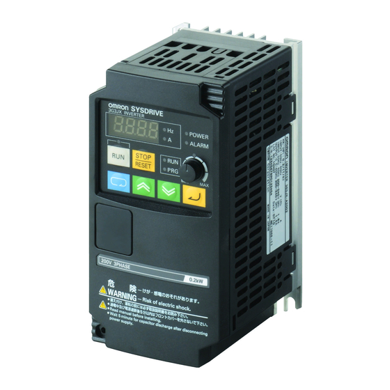
1-2 Appearance and Names of Parts 1-2 Appearance and Names of Parts Top cover Digital Operator Front cover Main housing FREQ (FREQUENCY) adjuster Bottom cover •The size of the fin varies with the motor capacity. •There are two sizes depending on the motor capacity, but the fundamental structure is the same. •Remove the front cover when connecting the power supply, the motor, and the control signal. - Page 21 1-2 Appearance and Names of Parts Names of Parts Inside the Front Cover Main circuit terminal block (input side) 8k8k8k8 Do not touch these! (ELECTRICAL HAZARD: For factory maintenance only) Communications connector Relay output terminal block Control circuit terminal block Main circuit terminal block (output side) S7: OPE/485 communications selector (Default = OPE side)
- Page 22 1-2 Appearance and Names of Parts...
- Page 23 Chapter 2 Design 2-1 Installation ............2-1 2-2 Wiring ..............2-6...
-
Page 24: Safety Information
2-1 Installation 2Design 2-1 Installation WARNING Turn off the power supply and implement wiring correctly. Not doing so may result in a serious injury due to an electric shock. Wiring work must be carried out only by qualified personnel. Not doing so may result in a serious injury due to an electric shock. -
Page 25: Precautions For Use
•Install the Inverter vertically on the wall or DIN tracks (optional). Install the Inverter on a nonflammable wall surface material, like metal. Positions for installing screws Position for installing a screw Model Model 3G3JX-A2015 3G3JX-A2002 A2022 A2004 A2037 A2007 A4004... -
Page 26: Installation Environment
5 cm min. 10 cm min. •You can install multiple 3G3JX Inverters side by side in the control panel (side-by-side installation). Again, keep the ambient temperature within the specified range (40°C or below). •If the ambient temperature is from 40°C through to 50°C, the carrier frequency should be reduced and the... - Page 27 2-1 Installation •To raise the carrier frequency, reduce the output current (or derate the rated current) as shown in the graph below. (1) Side-By-Side installation (ambient temperature:40°C) 0.4 to 2.2kW 0.2 to 2.2 · 5.5/7.5kW 200-V Class 400-V Class 5.5/kW 100% 100% 7.5kW...
-
Page 28: Installation
2-1 Installation •Before installing the Inverter, place a cover over all the ventilation openings to shield them from foreign objects. After completing the installation process, be sure to remove the covers from the Inverter before operation. Ventilation openings (Both sides and top) -
Page 29: Removing And Mounting The Front Cover
2-2 Wiring 2-2 Wiring Removing and Mounting the Front Cover Removing the Front Cover Loosen the mounting screw at the lower left of the front cover. Lift the bottom of the front cover to remove while holding the body. 1. Loosen the front cover mounting screw. 2. - Page 30 2-2 Wiring Mounting the Front Cover Hang the upper side of the front cover on the hooks, and push down both sides of the cover simultaneously until it clicks into place. 1. Hang the upper side on the hooks. (Two hooks) 2.
-
Page 31: Standard Connection Diagram
(1 to 2 kΩ) Frequency reference input (current) *1. The items in parentheses indicate terminal symbols for 3G3JX-AE *2. Connect a single-phase 200-V AC input to terminals L1 and N/L3. *3. By factory default, MA is set to NC contact, and MB to NO contact in the... - Page 32 2-2 Wiring Wiring to the Power Supply and Motor (Example) 3G3JX-A2004 (Example) 3G3JX-A2037 Main circuit terminal block (input side) Main circuit terminal block (input side) Main circuit terminal block (output side) Main circuit terminal block (output side) Power supply Ground...
-
Page 33: Wiring
2-2 Wiring Note 2: Connect securely to the ground as specified (type-D grounding for 200-V class, and type-C grounding for 400-V class). Do not share the grounding electrode with other strong electrical devices. Example of incorrect grounding Example of correct grounding Inverter Inverter Inverter... - Page 34 2-2 Wiring Wiring Example of the Control Circuit Terminal Block (Sink Logic) At sink logic (NPN) : External power supply input At source logic (PNP) : Power supply output Note: By factory default, the input logic of the multi-function input terminal circuit is set to the sink logic.
- Page 35 2-2 Wiring Selecting the Sequence Input Method (Sink/Source Logic) Logic Selection Method for the Multi-function Input Terminals When the internal power supply is used, you can switch the logic by rearranging the short-circuit bar on the control circuit terminal block. The default setting is sink logic. <Sink Logic>...
-
Page 36: Connecting The Main Circuit Terminals
Wiring Applicable device Motor output Fuse size Applicable Inverter model Earth leakage breaker (kW) Power cable (class J) (ELB) Rated 600 V 3G3JX-A2002 1.25 mm 10 A 3G3JX-A2004 10 A 1.25 mm 3G3JX-A4004 3G3JX-A2007 2.0 mm 10 A 15 A 0.75... - Page 37 A2055 to A2075 Main Circuit A4055 to A4075 Terminal Block *1. For 3G3JX-AE , R/L1 corresponds to L1, S/L2 to L2, and T/L3 to N/L3. Connect a single-phase 200-V AC input to terminals L1 and N/L3. Relay Output Control Circuit Terminal Block...
- Page 38 +1 and P/+2 when a DC Ground terminal electric shock and reduce noise.) reactor is not connected. For 3G3JX-AE 's terminal symbols, R/L1 corresponds to L1, S/L2 to L2, and T/L3 to N/L3. Connect a single-phase 200-V AC input to terminals L1 and N/L3. 2-15...
-
Page 39: Main Circuit Connection Diagram
•When choosing MCCB's time characteristics, be sure to consider the Inverter's overload protection (1 minute at 150% of the rated output current). •By programming the sequence as illustrated below, you can turn off the power via the relay outputs (MA, MB, and MC) for the 3G3JX Series. Molded-case circuit breaker... - Page 40 2-2 Wiring Installing a Magnetic Contactor (MC) •If the power supply of the main circuit is shut off due to sequencing, a magnetic contactor (MC) can be used. (When forcibly stopping the load with an MC on the primary side of the main circuit, however, the regenerative braking does not work and the load coasts to a stop (free run).) •Frequently opening and closing the magnetic contactor (MC) to start and stop a load may cause the Inverter to break down.
- Page 41 T/L3 (N/L3) Power supply P/+2 DC reactor P RB R1 R2 Regenerative braking unit * The items in parentheses indicate terminal symbols for 3G3JX-AE <Braking Resistors and Braking Resistor Units for the Inverter> Name Model Specifications 3G3AX-RBU21 For general use (with built-in resistor)
- Page 42 (MCCB) Power supply Input noise filter for Inverter Inverter * 3G3JX Molded-case circuit breaker (MCCB) Other device * Use a noise filter designed for Inverters. A general-purpose noise filter will be less effective and may not reduce noise.
- Page 43 Connect a noise filter to the output side of the Inverter to reduce induction and radio noise. Molded-case circuit breaker Power (MCCB) supply Inverter Noise filter 3G3JX 3G3AX-NFO Induction noise Radio noise Signal line Controller AM radio Induction noise: Electromagnetic induction can generate noise on the signal line, causing the controller to malfunction.
- Page 44 2-2 Wiring Cable Length Between Inverter and Motor Use a cable of 50 m or less between the Inverter and the motor. If the cable length is increased, the stray capacitance between the Inverter outputs and the ground is increased proportionally. An increase in stray capacitance causes high-frequency leakage current to increase, affecting the current detector in the Inverter's output unit and peripheral devices.
-
Page 45: Functions
2-2 Wiring Specifications of the Control Circuit Terminals Terminal Terminal name and function Default setting Specifications symbol 24 V DC ±10% External power supply terminal for input 30 mA max. signal (input).......At sink logic ⎯ Internal power supply output terminal for 24 V DC ±10% input signal (output)..At source logic 100 mA max. - Page 46 2-2 Wiring Functions and Connections of the Control Circuit Terminals Terminal Terminal Terminal name Function and connecting method Wire size function symbol Select functions and allocate them to terminals S1 to S5. Contact (The figure below illustrates the wiring of the sink logic.) input Multi-function (for...
- Page 47 2-2 Wiring *3. Below are the contact specifications of the relay output. Output Contact Resistance load Inductive load terminal capacity 250 V AC 2.5 A 250 V AC 0.2 A Max. 30V DC 3 A 30 V DC 0.7 A MA-MC 100 V AC 10 mA Min.
-
Page 48: Conforming To Ec Directives
The 3G3JX models have conformed to the EMC directive EN61800-5-1 by performing the machine installation and wiring as shown below. •The 3G3JX models are an open type device. Be sure to install it inside the control panel. •The power supply and voltage (SELV) with reinforced or double insulation should be used for wiring to the control circuit terminals. - Page 49 Chapter 3 Operation 3-1 Test Run Procedure ......... 3-3 3-2 Test Run Operation.......... 3-4 3-3 Part Names and Descriptions of the Digital Operator ............3-9 3-4 Operation Procedure (Example: Factory Default) ................3-11 3-5 Keys..............3-17 3-6 Parameter Transition ........3-18 3-7 Parameter List ..........
-
Page 50: Operation And Adjustment
3Operation WARNING Do not remove the front cover during the power supply and 5 minutes after the power shutoff. Doing so may result in a serious injury due to an electric shock. Do not operate the Digital Operator or switches with wet hands. Doing so may result in a serious injury due to an electric shock. - Page 51 Operation Stop Command •Provide a separate emergency stop switch because the STOP key on the Digital Operator is valid only when function settings are performed. •When checking a signal during the power supply and the voltage is erroneously applied to the control input terminals, the motor may start abruptly.
-
Page 52: Test Run Procedure
•Make sure that an appropriate power supply voltage is supplied and that the power input terminals (R/L1, S/L2, and T/L3) are wired correctly. 3G3JX-A2 : 3-phase 200 to 240 V AC 3G3JX-AE : 1/3-phase 200 to 240 V AC (Connect to L1 and N/L3 for 1 phase) 3G3JX-A4 : 3-phase 380 to 480 V AC •Make sure that the motor output terminals (U/T1, V/T2, and W/T3) are connected to the... -
Page 53: Test Run Operation
(R/L1, S/L2, and T/L3) are wired correctly. 3G3JX-A2 : 3-phase 200 to 240 V AC 3G3JX-AE : 1/3-phase 200 to 240 V AC (Connect to L1 and N/L3 for 1 phase) 3G3JX-A4 : 3-phase 380 to 480 V AC •Make sure that the motor output terminals (U/T1, V/T2, and W/T3) are connected to the motor correctly. -
Page 54: Parameter Initialization
3-2 Test Run Operation Parameter Initialization •Initialize the parameters using the following procedure. •To initialize the parameters, set parameter b084 to "02". Key sequence Display example Description k0.0 Power On Press the Mode key once, and then press the Decrement key three bk-k-k- times to display "b---". - Page 55 3-2 Test Run Operation Setting the Motor Capacity Selection (H003) and Motor Pole Number Selection (H004) Interrupt Parameter Register Unit of Default Name Description Setting range during setting setting 200-V class 0.2/0.4/0.75/ Motor Sets the capacity of the 1.5/2.2/3.7/ Varies H003 1165h capacity...
-
Page 56: Actual Load Operation
3-2 Test Run Operation No-load Operation •Start the no-load motor (i.e., not connected to the mechanical system) using the Digital Operator. * Before operating the Digital Operator, check that the FREQ adjuster is set to "MIN." * Make sure that the LED indicator above the FREQ adjuster and the RUN command LED indicator are lit. - Page 57 3-2 Test Run Operation Checking the Operating Status •After making sure that the operating direction is correct and that the Inverter is operating smoothly at a slow speed, increase the frequency reference. •By changing the frequency reference or the rotation direction, make sure that there is no vibration or abnormal sound from the motor.
-
Page 58: Part Names And Descriptions Of The Digital Operator
3-3 Part Names and Descriptions of the Digital Operator 3-3 Part Names and Descriptions of the Digital Operator Data display RUN command LED indicator FREQ adjuster Operation keys Name Description POWER LED indicator Lit when the power is supplied to the control circuit. ALARM LED indicator Lit when an Inverter error occurs. - Page 59 3-3 Part Names and Descriptions of the Digital Operator Name Description Enters the set value. Enter key (To change the set value, be sure to press the Enter key.) Changes the mode. Increment key Also, increases the set value of each function. Changes the mode.
-
Page 60: Operation Procedure (Example: Factory Default)
3-4 Operation Procedure (Example: Factory Default) 3-4 Operation Procedure (Example: Factory Default) Displaying the Monitor Mode, Basic Function Mode, and Extended Function Mode Power On 1. The data of the set monitor is displayed. (Default is "0.0") Press 2. The code of the monitor mode is displayed (as "d001"). •Press the Mode key once to return from the code display of the monitor mode to the monitor dk0k0k1... - Page 61 3-4 Operation Procedure (Example: Factory Default) 3. The code of the basic function mode is displayed (as "F001"). fk0k0k1 Press Press (4 times) (4 times) 4. The extended function mode is displayed (as "A---"). •Extended function mode Displays in order of A ⇔ b ⇔ C ⇔ H. ak-k-k- Press Press...
-
Page 62: Function Mode
3-4 Operation Procedure (Example: Factory Default) Setting Functions •Switch the method of the RUN command. (Digital Operator → Control terminal block) •To switch the method of the RUN command from the Digital Operator (factory default) to the control terminal block, you need to change the frequency reference selection (A001) from the Digital Operator (02) to the terminal (01). - Page 63 3-4 Operation Procedure (Example: Factory Default) (Change the A002 setting.) •Change the RUN command selection to the terminal "01". Press 4. The code of the monitor mode is displayed (as "A002"). •Press the Enter key to fix the changed setting data.
- Page 64 3-4 Operation Procedure (Example: Factory Default) 2. Change the function code. •You can change the 4th digit when "d" blinks. dk0k0k1 Press (2 times) ("A001" is displayed.) •"A" blinks. •Press the Enter key to fix the blinking digit. ak0k0k1 Press ("A"...
- Page 65 3-4 Operation Procedure (Example: Factory Default) ("A021" is displayed.) •"2" of the 2nd digit blinks. ak0k2k1 Press 5. Change the 1st digit of the function code. •"1" of the 1st digit blinks. •Press the Mode key to start "2" of the 2nd digit ak0k2k1 blinking again.
-
Page 66: Keys
3-5 Keys 3-5 Keys Name Description Switches between the command setting and the data setting, and between the extended function mode and the basic function mode. With this key, you can always change the display as follows. [Supplemental Information] To jump to "d001" from any function mode, hold down the Mode key for 3 seconds. -
Page 67: Parameter Transition
3-6 Parameter Transition 3-6 Parameter Transition dk0k0k1 Press the key dk0k8k3 fk0k0k1 fk0k0k4 ak0k0k1 ak-k-k- 0k0k0k0 ak0k0k1 0k0k0k1 9k9k9k9 bk-k-k- ak0k0k2 0k0k0k0 ck-k-k- 0k0k0k1 9k9k9k9 ak0k0k3 hk-k-k- *1. Data is not stored by pressing the Mode key. *2. Press the Enter key to store the data. *3. - Page 68 3-6 Parameter Transition * To display a specific monitor when the power is turned on, press the Enter key with that monitor displayed. If a parameter for an extended function code is stored after pressing the Enter key, however, that code (A---, b---, C---, d---, or H---) appears at the next power-on.
-
Page 69: Parameter List
3-7 Parameter List 3-7 Parameter List Monitor Mode (d ) / Basic Function Mode (F Changes Parameter Monitor or data range Default Name during Unit Page (Digital Operator) setting operation Output frequency ⎯ ⎯ d001 0.0 to 400.0 monitor ⎯ ⎯... -
Page 70: Extended Function Mode
3-7 Parameter List Changes Parameter Monitor or data range Default Name during Unit Page (Digital Operator) setting operation Electronic thermal ⎯ ⎯ d104 0.0 to 100.0 monitor Output frequency Starting frequency to 1st or 2nd max. ⎯ F001 setting/monitor frequency 0.01 to 99.99 F002 Acceleration time 1... - Page 71 3-7 Parameter List Changes Parameter Monitor or data range Default Function name during Unit Page (Digital Operator) setting operation 02: Switches between FV/FREQ adjuster via terminal AT 03: Switches between FI/FREQ adjuster via ⎯ A005 FV/FI selection terminal AT 04: FV input only 05: FI input only A011 FV start frequency 0.0 to Max.
- Page 72 3-7 Parameter List Changes Parameter Monitor or data range Default Function name during Unit Page (Digital Operator) setting operation Multi-step speed A021 reference 1 Multi-step speed A022 reference 2 Multi-step speed A023 reference 3 Multi-step speed A024 reference 4 Multi-step speed A025 reference 5 Multi-step speed...
- Page 73 3-7 Parameter List Changes Parameter Monitor or data range Default Function name during Unit Page (Digital Operator) setting operation Torque boost A041 selection 00: Manual torque boost only 4-12 01: Automatic (simple) torque boost *2nd torque boost A241 selection Manual torque A042 boost voltage 0.0 to 20.0...
- Page 74 3-7 Parameter List Changes Parameter Monitor or data range Default Function name during Unit Page (Digital Operator) setting operation Frequency upper A061 0.0/Frequency lower limit to Max. frequency limit 4-19 *2nd frequency 0.0/Frequency lower limit to 2nd Max. A261 upper limit frequency Frequency lower 0.0/Starting frequency to Frequency upper...
- Page 75 3-7 Parameter List Changes Parameter Monitor or data range Default Function name during Unit Page (Digital Operator) setting operation RUN mode 00: Normal operation A085 4-23 selection 01: Energy-saving operation Energy-saving response/ A086 0 to 100 4-23 accuracy adjustment Acceleration time A092 15.00 0.01 to 99.99...
- Page 76 3-7 Parameter List Changes Parameter Monitor or data range Default Function name during Unit Page (Digital Operator) setting operation 4-10 A101 FI start frequency 0.0 to 400.0 4-25 4-10 A102 FI end frequency 0.0 to 400.0 4-25 4-10 A103 FI start ratio 0.
- Page 77 3-7 Parameter List Changes Parameter Monitor or data range Default Function name during Unit Page (Digital Operator) setting operation 00: Alarm 01: 0 Hz start ⎯ b001 Retry selection 02: Frequency matching start 4-27 03: Trip after frequency matching deceleration stop Allowable b002...
- Page 78 3-7 Parameter List Changes Parameter Monitor or data range Default Function name during Unit Page (Digital Operator) setting operation Overload limit 00: Disabled b021 selection 01: Enabled in acceleration/constant speed ⎯ 4-31 operation *2nd overload limit b221 02: Enabled in constant speed operation selection 1.5 ×...
- Page 79 3-7 Parameter List Changes Parameter Monitor or data range Default Function name during Unit Page (Digital Operator) setting operation Selection of non- 00: Disabled stop function at b050 01: Enabled (Stop) 4-33 momentary power 02: Enabled (Restart) interruption Starting voltage of non-stop function b051 0.0 to 1000.
- Page 80 3-7 Parameter List Changes Parameter Monitor or data range Default Function name during Unit Page (Digital Operator) setting operation Frequency ⎯ b086 conversion 0.1 to 99.9 4-39 coefficient STOP key 00: Enabled ⎯ b087 4-39 selection 01: Disabled Free-run stop 00: 0 Hz start 4-39 ⎯...
- Page 81 3-7 Parameter List Changes Parameter Monitor or data range Default Function name during Unit Page (Digital Operator) setting operation 00: FW (forward) Multi-function 01: RV (reverse) C001 input 1 selection 02: CF1 (multi-step speed setting binary 1) 03: CF2 (multi-step speed setting binary 2) *2nd multi-function 04: CF3 (multi-step speed setting binary 3) C201...
- Page 82 3-7 Parameter List Changes Parameter Monitor or data range Default Function name during Unit Page (Digital Operator) setting operation 00: RUN (signal during RUN) 01: FA1 (constant speed arrival signal) Multi-function 02: FA2 (over set frequency arrival signal) C021 output terminal P1 03: OL (overload warning) selection 04: OD (excessive PID deviation)
- Page 83 3-7 Parameter List Changes Parameter Monitor or data range Default Function name during Unit Page (Digital Operator) setting operation Operator/ModBus 02: Digital Operator ⎯ C070 selection 03: ModBus Communication 04: 4800 bps speed selection ⎯ C071 05: 9600 bps (Baud rate 4-79 06: 19200 bps selection)
- Page 84 3-7 Parameter List Changes Parameter Monitor or data range Default Function name during Unit Page (Digital Operator) setting operation AM offset 4-35 C086 0.0 to 10.0 adjustment 4-75 Use "00". ⎯ ⎯ ⎯ C091 Not used *Do not change. 00: Do not store the frequency data ⎯...
- Page 85 Chapter 4 Functions 4-1 Monitor Mode............ 4-1 4-2 Function Mode..........4-5...
-
Page 86: Monitor Mode
4-1 Monitor Mode 4Functions 4-1 Monitor Mode Output Frequency Monitor [d001] Displays the output frequency of the Inverter. The monitor LED indicator "Hz" lights up while d001 is displayed. (Display) 0.0 to 400.0: Displays in increments of 0.1 Hz. Output Current Monitor [d002] Displays the output current value of the Inverter. - Page 87 4-1 Monitor Mode Multi-function Input Monitor [d005] Displays the input status of the multi-function input terminals. C011 to C015 (contact selection) are excluded. (Example) Multi-function input terminals S4, S2 : ON Multi-function input terminals S5, S3, S1 : OFF Display (OFF) (ON) (OFF) (ON) (OFF) Multi-function input monitor Multi-function Output Monitor [d006]...
- Page 88 4-1 Monitor Mode Output Voltage Monitor [d013] Displays the output voltage value (Vac) of the Inverter. The monitor LED indicator "V" lights up. (Display) 0. to 600.: Displays in increments of 1 V. Total RUN Time [d016] Displays the Inverter RUN time. (Display) 0.
- Page 89 4-1 Monitor Mode Fault Monitors 1[d081], 2[d082], 3[d083] Displays the details of the last three trips. The most recent trip is displayed on trip monitor 1. (Display) •Factor (E01 to E60) •Output frequency at the time of tripping (Hz) •Output current at the time of tripping (A) •Internal DC voltage at the time of tripping (V) •Total RUN time before the trip (hr) •Total power supply time before the trip (hr)
- Page 90 4-2 Function Mode 4-2 Function Mode <Group F: Basic Function Parameter> Output Frequency Setting/Monitor •Set the Inverter output frequency. •With the frequency reference set to the Digital Operator ([A001] = 02), you can set the output frequency in F001. For other methods, refer to the [A001] section in "Frequency Reference Selection"...
- Page 91 4-2 Function Mode •The set time here indicates the acceleration/deceleration time between 0 Hz and the maximum frequency. Output frequency Max. frequency A004/A204 Output frequency set value Actual Actual deceleration acceleration time time F002/F202 F003/F203 Even if a short acceleration/deceleration time is set, the actual time cannot be shorter than the minimum acceleration/deceleration time that is determined by the mechanical inertia moment and the motor torque.
-
Page 92: Frequency Reference Selection
4-2 Function Mode <Group A: Standard Function Parameter> Frequency Reference Selection Select the method of the frequency reference. Parameter No. Function name Data Default setting Unit Frequency reference 00: Digital Operator (FREQ adjuster) A001 selection 01: Terminal ⎯ 02: Digital Operator (F001) 2nd frequency 03: ModBus communication A201... -
Page 93: Base Frequency
4-2 Function Mode Base Frequency Base Frequency and Motor Voltage Match the Inverter output (frequency/voltage) to the motor rating. Be careful, especially if you set a base frequency at below 50 Hz. Otherwise, the motor may burn out. Parameter No. Function name Data Default setting... - Page 94 4-2 Function Mode Parameter No. Function name Data Default setting Unit A004 Maximum frequency 30 to 400 60.0 2nd maximum A204 frequency Related functions A003, A203, A081, A082 * To switch to the 2nd max. frequency, allocate 08 (SET) to the multi-function input terminal and then turn it on. Analog Input (FV, FI) The Inverter has two types of analog input terminals.
- Page 95 4-2 Function Mode External Frequency (Voltage/Current) Adjustment External Analog Input (Frequency Reference) FV-FC terminal: 0 to 10 V (voltage input) FI-FC terminal: 4 to 20 mA (current input) Also set an output frequency for the FREQ adjuster on the Digital Operator. Parameter No.
- Page 96 4-2 Function Mode FV, FI Sampling Set the built-in filter applied to frequency setting signals via external voltage/current input. Parameter No. Function name Data Default setting Unit A016 FV, FI sampling 1. to 17. Time Related functions A011 to A016, C001 to C005 •Helps remove noise in the frequency setting circuit.
- Page 97 4-2 Function Mode Jogging Operation Function The motor rotates while the input is turned ON. For details on the operation and settings, refer to "Jogging Operation" (page 4-48). Parameter No. Function name Data Default setting Unit A038 Jogging frequency 0.00/Starting frequency to 9.99 6.00 00: Free-run stop A039...
- Page 98 4-2 Function Mode Control Method (V/f Characteristics) Constant Torque Characteristics (VC) •Ouput voltage is proportional to output frequency. While proportional from 0 Hz to base frequency, the output voltage is constant from base to maximum frequencies regardless of the frequency. Output voltage (100%)
-
Page 99: Torque Boost
4-2 Function Mode Torque Boost This function helps compensate for insufficient motor torque in a low speed range. •Compensates for the voltage drop caused by the primary resistance of the motor or by wiring to suppress torque reduction in a low speed range. •To select the simple torque boost in the torque boost selection (A041/A241), set the motor capacity selection (H003/H203) and motor pole number selection (H004/H204) according to your motor. - Page 100 4-2 Function Mode DC Injection Braking (DB) This function securely stops the motor rotation during deceleration. Parameter No. Function name Data Default setting Unit 00: Disabled DC injection braking 01: Enabled ⎯ A051 selection 02: DB when output frequency < A052 DC injection braking A052 0.0 to 60.0...
- Page 101 4-2 Function Mode (a) Edge operation (A056: 00) (b) Level operation (A056: 01) (Example 1-a) (Example 1-b) Output frequency Output frequency A055 (Example 2-a) (Example 2-b) Output frequency Output frequency A055 (Example 3-a) (Example 3-b) Free running Output frequency Output frequency Free running A053 A055...
- Page 102 4-2 Function Mode Internal DC Injection Braking (A051 = 01) •Performs DC injection braking to stop the motor without any terminal operation. To use this function, set the DC injection braking selection (A051) to 01. •Set the DC injection braking power in A054. •Set the frequency for starting DC injection braking in A052.
- Page 103 4-2 Function Mode Internal DC Injection Braking (Operates Only at the Set Frequency: A051 = 02) DC injection braking is enabled when the output frequency becomes lower than the DC injection braking frequency (A052) during operation. •Neither external (A051 = 00) nor internal (A051 = 01) DC injection braking is available while this function is selected.
-
Page 104: Frequency Limit
4-2 Function Mode Frequency Limit This function limits the Inverter output frequency. Parameter No. Function name Data Default setting Unit 0.0/Frequency lower limit [A062] to A061 Frequency upper limit Max. frequency [A004] 2nd frequency upper 0.0/Frequency lower limit [A262] to A261 limit Max. -
Page 105: Pid Function
4-2 Function Mode Output frequency A068 A067 A068 A066 A065 A066 A064 A063 A064 Frequency reference PID Function This function enables process control of such elements as flow rate, air volume, and pressure. Parameter No. Function name Data Default setting Unit 00: Disabled ⎯... - Page 106 4-2 Function Mode Target Value Selection •The target value depends on the terminal selected in frequency reference A001 other than that in A076. You cannot set analog inputs FV and FI to both target and feedback values simultaneously. Do not connect the signal lines for inputs FV and FI simultaneously.
- Page 107 4-2 Function Mode D Operation •Operation where the control volume is proportional to the variation ratio of the target value Target value Large Large A074 A074 Small Control volume Small •PI operation is the combination of the above P and I operations; PD is P and D operations; PID is P, I and D operations.
-
Page 108: Avr Function
4-2 Function Mode AVR Function •This function outputs voltage to the motor correctly even if the incoming voltage to the Inverter fluctuates. With this function, output voltage to the motor is based on that set in the AVR voltage selection. Parameter No. - Page 109 4-2 Function Mode 2-step Acceleration/Deceleration Function This function changes the acceleration/deceleration time during such operations. Parameter No. Function name Data Default setting Unit 0.01 to 99.99 A092 Acceleration time 2 15.0 100.0 to 999.9 A292 2nd acceleration time 2 15.0 1000.
- Page 110 4-2 Function Mode Acceleration/Deceleration Pattern This function is used when smooth acceleration/deceleration is needed. Parameter No. Function name Data Default setting Unit Acceleration pattern 00: Line ⎯ A097 selection 01: S-shape curve Deceleration pattern 00: Line ⎯ A098 selection 01: S-shape curve •Acceleration/deceleration pattern can be set according to each system.
-
Page 111: Frequency Addition Function
4-2 Function Mode Operation Frequency Function This function makes calculations for two inputs and reflects the result as the output frequency. Parameter No. Function name Data Default setting Unit Operation frequency input 00: Digital Operator (F001) ⎯ A141 A setting 01: Digital Operator (FREQ adjuster) 02: Input FV Operation frequency input... - Page 112 4-2 Function Mode Frequency reference source A001 FREQ adjuster Terminal block Output frequency setting Σ F001 set value ModBus communication +/– Logic operation output Addition direction setting A146 Frequency addition A145 [ADD] Multi-function input VR Adjustment Function Parameter No. Function name Data Default setting Unit...
- Page 113 4-2 Function Mode Parameter No. Function name Data Default setting Unit Momentary power interruption/ 00: Disabled ⎯ b004 undervoltage trip during 01: Enabled stop selection Momentary power 00: 16 times ⎯ b005 interruption retry time 01: No limit selection 00: Frequency at interruption Starting frequency at ⎯...
-
Page 114: Electronic Thermal Function
4-2 Function Mode Alarm Selection for Momentary Power Interruption/Undervoltage During Stop •Use b004 to select whether to enable an alarm output in case of momentary power interruption or undervoltage. •An alarm output continues while Inverter control power supply remains. Alarm output for momentary power interruption and undervoltage during stop (Examples 3 and 4) (Example 3) b004: 00 While the Inverter is stopped While the Inverter is running... - Page 115 •The lower the output frequency is, the lower the cooling capability of the standard motor's self- cooling fan. Reduced Torque Characteristics 1 •Multiplied by the time limit characteristics set in b012/212 for each frequency. (Example) 3G3JX-A2007 (Rated current: 4.0 A), b012 = 4.00 (A), Output frequency = 20 Hz Electronic thermal level Trip time (s) X1.0...
- Page 116 4-2 Function Mode Reduced Torque Characteristics 2 •Multiplied by the time limit characteristics set in b012/212 for each frequency. (Example) 3G3JX-A2007 (Rated current: 4.0 A), b012 = 4.00 (A), Output frequency = 40 Hz Electronic thermal level Time before trip (s) X1.0...
- Page 117 4-2 Function Mode • With the overload limit parameter set too low, an overvoltage trip may occur due to regenerative energy from the motor. This is because of automatic deceleration from this function even during acceleration. • Make the following adjustments if this function operates during acceleration and the frequency doesn't reach the target level.
- Page 118 4-2 Function Mode Soft Lock Function Use this function to prohibit writing of each parameter. This helps prevent data rewrite due to erroneous operation. For the soft lock selection through the signal input from the terminal (b031 = 00 or 01), refer to the Soft Lock Function of the Multi-function Input section in "Soft Lock Function"...
- Page 119 4-2 Function Mode Power supply Internal DC b052 voltage b051 Undervoltage level Output frequency b054 b053 b053 b053 Operation Description A If the power is disconnected during operation with the momentary power interruption non-stop function enabled (b050 = 01) and the voltage falls below the momentary power interruption non- stop function starting voltage (b051), the output frequency is decelerated with one stroke in accordance with the momentary power interruption non-stop deceleration starting width (b054) (Internal DC voltage rises due to the regenerative energy generated at this time.)
- Page 120 4-2 Function Mode Overvoltage Control Function During Deceleration This function helps avoid an overvoltage trip during deceleration. Note that the actual deceleration time may be longer than the set value. This function automatically keeps DC voltage at the set level during deceleration.
-
Page 121: Starting Frequency
4-2 Function Mode Refer to "Analog Output AM Terminal" (page 4-75). AM output b080 Adjust the gain with reference to voltage at 0%. C086 Adjust the offset. (Parallel shift) Output frequency or output current 100% Note: If the offset (C086) is changed, the point to reach 10 V changes accordingly because of par- allel movement. - Page 122 4-2 Function Mode •To raise the carrier frequency, reduce the output current (or derate the rated current) as shown in the graph below. (1) Side-By-Side installation (ambient temperature:40°C) 0.4 to 2.2kW 0.2 to 2.2 · 5.5/7.5kW 400-V Class 200-V Class 5.5/kW 100% 100%...
- Page 123 4-2 Function Mode Parameter Initialization You can initialize the rewritten set values and reset to the factory default, or clear trip records. Note that this is not available for RUN and power ON times. Parameter No. Function name Data Default setting Unit 00: Clears the trip monitor 01: Initializes data...
-
Page 124: Stop Key Selection
4-2 Function Mode Frequency Conversion Coefficient This function displays a conversion value obtained by multiplying the Inverter output frequency by the coefficient set in [b086]. This helps display the actual physical value on the monitor. Parameter No. Function name Data Default setting Unit Frequency conversion... -
Page 125: Cooling Fan Control
4-2 Function Mode Main Unit Monitor Display Selection You can select what items to display on the monitor when the ModBus communication or the Digital Operator is connected with the communications connector on the Inverter. Parameter No. Function name Data Default setting Unit 01: Output frequency monitor... - Page 126 4-2 Function Mode Overvoltage LAD Stop Function This function helps avoid an overvoltage trip due to regenerative energy from the motor during deceleration. Note that the actual deceleration time may be longer than the set value. If DC voltage exceeds the set level, the Inverter stops deceleration. The aim of this function is the same as the overvoltage control function during deceleration, described in b055 and b056.
-
Page 127: Overcurrent Suppression Function
4-2 Function Mode Overcurrent Suppression Function •This function suppresses overcurrent caused by a steep current rise in rapid acceleration. •Select to enable or disable the overcurrent suppression function in b140. •This function does not operate during deceleration. Parameter No. Function name Data Default setting Unit... - Page 128 4-2 Function Mode <Group C: Multi-function Terminal Function> The 3G3JX has five input terminals [S1], [S2], [S3], [S4] and [S5]; one open collector output terminal [P1]; two relay output terminals [MA] and [MB] (SPDT contact); and one analog output terminal [AM].
- Page 129 4-2 Function Mode Parameter No. Function name Data Default setting Unit Multi-function input 1 00: FW (forward) C001 selection 01: RV (reverse) ⎯ 02: CF1 (multi-step speed setting binary 1) *2nd multi-function input 03: CF2 (multi-step speed setting binary 2) C201 1 selection 04: CF3 (multi-step speed setting binary 3)
-
Page 130: Wiring Example
4-2 Function Mode Emergency Shutoff Input Function Emergency Shutoff Mode Selection To select Emergency Shutoff mode in the 3G3JX, turn on switch S8 on the right side behind the front cover. Switch S8 (right side) [Notes] Use caution when turning on/off the DIP switch S8 on the control PCB. That will change the function allocation on the control terminal block automatically. - Page 131 4-2 Function Mode Inputting EMR to the digital input lets the motor go into "Emergency Shutoff" status (or free-run status). This status continues while EMR is turned on or until a reset signal is input. To use the Inverter to control the mechanical brake (used for cranes, etc.), you need to connect the safety output of the external safety relay to the brake control circuit in series.
- Page 132 4-2 Function Mode Multi-step Speed Operation Function You can set RUN speeds using codes and switch the set speeds via the terminal. Data Symbol Function name Status Description Binary operation 1: ON Multi-step speed setting binary 1 Binary operation 1: OFF Binary operation 2: ON Multi-step speed setting binary 2 Binary operation 2: OFF...
-
Page 133: Jogging Operation
4-2 Function Mode •You can also select a multi-step speed by turning on/off the multi-step speed terminals (CF1 to CF4) and set the multi-step speed frequency with F001. Multi-step speed terminals Reflected speed Multi-step speed Reference source according to the A001 setting A021 A022 A023... - Page 134 4-2 Function Mode Jogging Frequency (When A039 = 01) Output frequency A038 •If the frequency is set to a higher value, the jogging operation may easily lead to a trip. Adjust A038 so that the Inverter does not trip. Jogging Stop Selection Note 1: To perform the jogging operation, turn on the JG terminal before the FW or RV terminal.
- Page 135 4-2 Function Mode •Perform each setting according to your system after selecting the level or edge operation in A056. (a) Edge operation (A056 = 00) (b) Level operation (A056 = 01) (Example 1-a) (Example 1-b) Output Output frequency frequency A055 (Example 2-a) (Example 2-b) Output...
- Page 136 4-2 Function Mode 2nd Control Function and Special 2nd Function This function is used to operate by switching two different types of motors. Data Symbol Function name Status Description Enables the parameter for the 2nd motor. 2nd control Disables the parameter for the 2nd motor. Enables the parameter for the special 2nd motor.
- Page 137 4-2 Function Mode Selection Parameter No. Function name SP-SET A042/A242 Manual torque boost voltage A043/A243 Manual torque boost frequency A044/A244 V/f characteristics selection A045/A245 Output voltage gain A061/A261 Frequency upper limit A062/A262 Frequency lower limit A092/A292 Acceleration time 2 A093/A293 Deceleration time 2 A094/A294 2-step acceleration/deceleration selection...
- Page 138 4-2 Function Mode •For instructions on how to switch on/off this function automatically with an arbitrary frequency, refer to "2-step Acceleration/Deceleration Function" (page 4-24). •To switch via a multi-function input, allocate 09 (2CH) to it. (Example 1) When A094/A294 is set to 00 (Example 2) When A094/A294 is set to 01 Acceleration 2 Deceleration 2...
-
Page 139: External Trip
4-2 Function Mode (Example 1) 0 Hz start (Example 2) Frequency pull-in restart Free Free running 0 Hz start running Motor rotation Motor rotation speed speed b003 Frequency pull-in start • Starts at 0 Hz regardless of motor rotation speed. The retry wait time is ignored. •... - Page 140 4-2 Function Mode Power Recovery Restart Prevention Function For safety reasons, this function causes a USP trip (E13) while the RUN command (FW/RV) from the control terminal (terminal) is turned on, in either of the following conditions: • When the power is turned on •...
- Page 141 4-2 Function Mode •Select the soft lock setting and performing method from the following table. Parameter No. Function name Data Default setting Unit 00: Data other than b031 cannot be changed when the SFT terminal is ON. 01: Data other than b031 and specified frequency parameters cannot be changed when the SFT terminal is ON.
-
Page 142: Thermistor Trip Function
4-2 Function Mode •You can also reset an Inverter trip by pressing the STOP/RESET key on the Digital Operator. •In reset selection C102, you can select alarm reset timing and either enable/disable in normal operation. •For the RS terminal, only NO contact is available. Parameter No. - Page 143 4-2 Function Mode 3-wire Input Function This function is effective in using auto recovery contacts such as a press button switch for operation and stop. Data Symbol Function name Status Description Starts with auto recovery contacts. 3-wire start Irrelevant to the motor operation. Stops with auto recovery contacts.
- Page 144 4-2 Function Mode PID Enable/Disable and PID Integral Reset The PID enable/disable function disables the PID function temporarily through terminal input. This overrides the A071 setting to control the motor frequency. Also, the PID integral reset function clears the PID integral value that has until then been integrated through terminal input. This helps stop the motor when the frequency control is shifted to the PID control.
- Page 145 4-2 Function Mode [UP/DOWN Function Enabled/Disabled] Frequency reference selection (A001) Multi-step speed Jogging Enabled/Disabled ⎯ ⎯ Disabled ⎯ Enabled Disabled Disabled Enabled Disabled •The UP/DOWN function is disabled when the JG operation is enabled. •The UP/DOWN function is enabled when the frequency reference selection (A001) is set to the Digital Operator (02).
- Page 146 4-2 Function Mode Frequency Addition Function This function allows you to add/subtract the constant offset frequency to/from the output frequency. Data Symbol Function name Status Description Calculates the set value in A145 against the set frequency in A001 according to the formula specified in A146, in Frequency addition order to provide a new frequency reference.
- Page 147 4-2 Function Mode Ready Function Data Symbol Function name Status Description The Inverter is ready. Ready function Normal stop status Related functions C001 to C005 •Inputting this signal shortens the time between the RUN command input and the start of actual operation.
- Page 148 4-2 Function Mode Data Description Reference item Page FBV: PID FB status output PID FB status output 4-67 NDc: Network error Network error 4-68 LOG: Logic operation output Logic operation result output 4-69 — — ODc: Do not use. LOC: Light load detection signal Light load detection signal 4-70 Signal During RUN...
- Page 149 4-2 Function Mode •Below is the hysteresis of the frequency arrival signal: ON: (Set frequency - 1% of the maximum frequency) (Hz) OFF: (Set frequency - 2% of the maximum frequency) (Hz) Parameter No. Function name Data Default setting Unit 0.0: Does not output arrival signal during Arrival frequency acceleration...
- Page 150 4-2 Function Mode Overload Warning Signal If the load is too large, this function outputs an overload warning signal, allowing you to readjust the load level to prevent a trip. This helps prevent mechanical damage due to an overload, or a conveyor line stop due to an over- load trip of the Inverter.
-
Page 151: Alarm Output
4-2 Function Mode •C044 can be set from 0 to 100. The setting corresponds to the range of 0 to the maximum target value. Feedback value C044 Target value C044 Alarm Output This is output when the Inverter trips. If you use the relay for alarm outputs, set and check operation,, as the SPDT contact is used for the terminals. - Page 152 4-2 Function Mode •The disconnection detection signal is output if the frequency reference of the external analog input remains below the starting frequency for 500 ms. •The signal stops 500 ms after the frequency reference has exceeded the starting frequency. •Helps detect disconnection when a frequency reference is issued from the external analog inputs (FV, FI) with the frequency reference selection set to the terminal (A001 = 01).
- Page 153 4-2 Function Mode Network Error This function detects and outputs a network error during RS485 ModBus communication. •The error is output during RS485 ModBus communication if the next signal does not come even after the specified time period in C077. Data Symbol Function name...
- Page 154 4-2 Function Mode Logic Operation Result Output This function outputs a logic operation result of the set two status. Data Symbol Function name Status Description Logic operation output See the figure below. Available input terminals P1-PC, MA-MC (or MB-MC) Required settings C021, C026, C141, C142, C143 Multi-function output item C141...
- Page 155 4-2 Function Mode Light Load Detection Signal This function outputs a signal when the Inverter output current has fallen below the C039 set value. Data Symbol Function name Status Description Output current is lower than the C039 set value. Light load detection signal Output current is higher than the C039 set value.
- Page 156 4-2 Function Mode ON delay OFF delay ON delay OFF delay Original signal waveform (without delay) ON delay only OFF delay only ON and OFF delays Multi-function Output Terminal Contact Selection This function allows you to set either contact for the two multi-function output terminals respectively. Parameter No.
- Page 157 4-2 Function Mode Specifications of the Relay Output Terminals •The relay output terminals are set to the SPDT contact. The following shows their operations. Electrical specifications Output terminal Resistance load Inductive load Max. contact 250 V AC, 2 A 250 V AC, 0.2 A capacity 30 V DC, 3 A 30 V DC, 0.6 A...
-
Page 158: Analog Input
4-2 Function Mode Analog Input Two types of external analog inputs are available for frequency reference. For voltage input, you can set a frequency from 0 to maximum by applying a voltage from 0 to 10 V between inputs FV and FC. For current input, apply 4 to 20 mA between inputs FI and FC. Note that voltage and current cannot be input simultaneously. - Page 159 4-2 Function Mode FV/FI Adjustment Parameter No. Function name Data Default setting Unit C081 FV adjustment 0.0 to 200.0 C082 FI adjustment 0.0 to 200.0 Related functions A011, A101, A012, A102, A013, A103, A014, A104, A015, A105 •You can adjust the FV/FI frequency input. •Use this to change the full scale of input.
- Page 160 4-2 Function Mode Analog Output AM Terminal This function allows you to monitor the output frequency and current from the AM terminal on the control terminal block (terminal). •Analog voltage output from 0 to 10 V. AM Selection •Select a signal to output from the following table. Parameter No.
-
Page 161: Stabilization Parameter
4-2 Function Mode <Group H: Motor Control Parameters> Motor Capacity and Pole Number Set the capacity and number of poles of the motor connected to the Inverter. •With incorrect parameters set, appropriate operation cannot be ensured. Parameter No. Function name Data Default setting Unit... -
Page 162: Communication Function
4-2 Function Mode Communication Function •Communication with external network control devices can be carried out from the communication connector of the 3G3JX, through the RS-485 complying ModBus-RTU protocol. Communication Specifications Item Description Note Transfer speed 4800/9600/19200 bps Select using the Digital Operator. - Page 163 To connect the ModBus, connect each Inverter in parallel as below. Connect a termination resistor separately to avoid signal reflection, since this 3G3JX does not incorporate it. Choose a termination resistor according to the impedance characteristics of the cable to be used.
- Page 164 4-2 Function Mode ModBus-Related Parameter Settings ModBus communication requires the following settings. Be sure to set the parameters shown below. In case the parameter settings are changed, ModBus communication will not start until the Inverter is turned ON again, even if "485" is selected with the 485/OPE selector. The parameters of C070s cannot be changed or set through ModBus communication.
-
Page 165: Modbus Communication Protocol
Binary data (1-bit long) that can be referred to or changed Holding register 16-bit long data that can be referred to or changed <Function Code> •Specifies a function for the Inverter to perform. •The function codes available to the 3G3JX are shown on the next page. 4-80... - Page 166 4-2 Function Mode Function code Maximum number of data Maximum data number in 1 Function code Function bytes in 1 message message Coil status reading 32 coils (in bits) Holding register content reading 4 registers (in bytes) Writing into the coil 1 coil (in bits) Writing into holding register 1 registers (in bytes)
- Page 167 4-2 Function Mode Message configuration: Response <Total Communication Time> •The time between receiving query and the response by the Inverter is the total of the silent interval (3.5-character length) and C078 (communication wait time) setting. •When sending another query to the Inverter after receiving the response from the Inverter, be sure to provide the silent interval length (3.5-character length or more) at the minimum.
-
Page 168: Explanation Of Each Function Code
4-2 Function Mode <No Response> The Inverter ignores a query and does not respond when: •The broadcast is received. •A communication error is detected in receiving a query. •The query slave address does not correspond with the slave address set for the Inverter. •The time interval between 2 pieces of data constituting the message is less than a 3.5-character length. - Page 169 •Reads the latest trip information (frequency, current, voltage at trip) from the Inverter with the slave address "1". •Refer to the trip status as follows: D081 D081 3G3JX command D081 (Factor) D081 (Frequency) (Output current) (DC bus V DC) Register No.
- Page 170 4-2 Function Mode Query Response Example Example Field name Field name (Hex) (Hex) Slave address*1 Slave address Function code Function code Register start address Number of data bytes (MSB) Register start address Register data 1 (MSB) (LSB) Number of holding Register data 1 (LSB) registers (MSB) Number of holding...
- Page 171 4-2 Function Mode Refer to "<Exception Response>" (4-89) if the holding register content reading command has not been performed normally. <Writing Into the Coil [05h]> Writes into one coil. The coil status change is shown in the following table. Coil status Data OFF →...
- Page 172 4-2 Function Mode Query Response Example Example Field name Field name (Hex) (Hex) Slave address Slave address Function code Function code Register address Register address (MSB) (MSB) Register address Register address (LSB) (LSB) Change data (MSB) Change data (MSB) Change data (LSB) Change data (LSB) CRC-16 (MSB) CRC-16 (MSB)
- Page 173 4-2 Function Mode <Writing Into Multiple Coils [0Fh]> Rewrites consecutive multiple coils. (Example) Change the status of multi-function input terminals [S1] to [S5] of the Inverter with the slave address "8". Refer to the following table for the status of multi-function input terminals [S1] to [S5]. Multi-function [S1] [S2]...
- Page 174 4-2 Function Mode Query Response Example Example Field name Field name (HEX) (HEX) Slave address Slave address Function code Function code Start address (MSB) Start address (MSB) Start address (LSB) Start address (LSB) Number of holding Number of holding registers (MSB) registers (MSB) Number of holding Number of holding...
- Page 175 4-2 Function Mode Function code Exception code Exception Query Code Description response Specified an unsupported function. Specified address does not exist. Specified data has an unacceptable format. Data is out of the Inverter's range for writing into the holding register. The Inverter does not allow this function.
- Page 176 4-2 Function Mode Register Number List R/W in the list shows whether the coil or holding register accepts reading and/or writing. R: Read only R/W: Read and write enabled Coil Number List Coil No. Item Description ⎯ 0000h Not used 1: RUN 0001h RUN commands...
- Page 177 4-2 Function Mode Coil No. Item Description 0015h Excessive PID deviation signal 0016h Overload warning signal Frequency arrival signal 0017h 1: ON (Over set frequency) 0: OFF Frequency arrival signal 0018h (At a constant speed) 0019h Signal during RUN 1: Writing 001Ah Data writing 0: Normal...
- Page 178 4-2 Function Mode Register Parameter Function name Monitor or data range Resolution Function 0 to 63 ⎯ 1007h Multi-function input monitor d005 Multi-function input status, Bit 0 = [1] to Bit 4 = [5] 0 to 7 Multi-function output status, ⎯...
- Page 179 4-2 Function Mode Register Parameter Function name Monitor or data range Resolution Function ⎯ 0026h Trip monitor 3: Factor code 0028h Trip monitor 3: Frequency 0.1 [Hz] 002Ah Trip monitor 3: Current 0.1 [A] 002Bh Trip monitor 3: Voltage 1. [V] Fault monitor 3 d083 002Ch...
- Page 180 4-2 Function Mode Register Parameter Function name Monitor or data range Resolution Function 1020h FV start frequency A011 0 to 4000 0.1 [Hz] 1022h FV end frequency A012 0 to 4000 0.1 [Hz] 1023h FV start ratio A013 0 to 100 1 [%] 1024h FV end ratio...
- Page 181 4-2 Function Mode Register Parameter Function name Monitor or data range Resolution Function Manual torque boost 104Ch A043 frequency 0 to 500 0.1 [%] 2nd manual torque boost 1512h A243 frequency 104Dh V/f characteristics selection A044 00: VC ⎯ 01: 1.7th power of VP 2nd V/f characteristics 1513h A244...
- Page 182 4-2 Function Mode Register Parameter Function name Monitor or data range Resolution Function 00: Feedback (FI) 01: Feedback (FV) 106Dh PID feedback selection A076 -⎯ 02: External communication 10: Operation function output OFF (Deviation = Target value - Feedback value) ⎯...
- Page 183 4-2 Function Mode Register Parameter Function name Monitor or data range Resolution Function 2-step acceleration/ 1078h A094 deceleration selection 00: Switched via terminal 2CH ⎯ 01: Switched by setting 2nd 2-step acceleration/ 151Dh A294 deceleration selection 2-step acceleration 107Ah A095 frequency 0 to 4000 0.1 [Hz]...
- Page 184 4-2 Function Mode Register Parameter Function name Monitor or data range Resolution Function Allowable momentary power 10A6h b002 3 to 250 0.1 [s] interruption time 10A7h Retry wait time b003 3 to 1000 0.1 [s] Momentary power 00: Disabled ⎯ 10A8h interruption/undervoltage b004...
- Page 185 4-2 Function Mode Register Parameter Function name Monitor or data range Resolution Function 00: Data other than b031 cannot be changed when terminal SFT is ON. 01: Data other than b031 and the specified frequency parameter cannot be changed when terminal SFT is ON.
- Page 186 4-2 Function Mode Register Parameter Function name Monitor or data range Resolution Function 00: Enabled ⎯ 10D6h STOP key selection b087 01: Disabled 00: 0 Hz start ⎯ 10D7h Free-run stop selection b088 01: Frequency pull-in restart 01: Output frequency monitor 02: Output current monitor 03: Rotation direction monitor ⎯...
- Page 187 4-2 Function Mode Register Parameter Function name Monitor or data range Resolution Function Multi-function input 1 1103h C001 selection 2nd multi-function input 1 1532h C201 selection Multi-function input 2 1104h C002 selection 00: FW/01: RV/02: CF1/03: CF2/04: 2nd multi-function input 2 1533h C202 CF3/05: CF4/06: JG/07: DB/08: SET/09:...
- Page 188 4-2 Function Mode Register Parameter Function name Monitor or data range Resolution Function 1124h Overload warning level C041 0 to 20000 0.01 [%] Set to10000 at rated current 153Ah 2nd overload warning level C241 Arrival frequency during 1126h C042 0 to 4000 0.1 [Hz] acceleration Arrival frequency during...
- Page 189 4-2 Function Mode Register Parameter Function name Monitor or data range Resolution Function 1153h Output terminal P1 ON delay C144 0 to 1000 Output terminal P1 OFF 1154h C145 0 to 1000 delay 0.1 [s] 1157h Relay output ON delay C148 0 to 1000 1158h...
- Page 190 4-2 Function Mode 4-105...
-
Page 191: Special Display List
Chapter 5 Maintenance Operations 5-1 Special Display List ......... 5-1 5-2 Troubleshooting..........5-5... -
Page 192: Error Code List
5-1 Special Display List 5Maintenance Operations 5-1 Special Display List Error Code List Display on Digital Name Description Operator Constant ek_k0k1 speed If the motor is restrained, or rapidly accelerated or decelerated, a large current flows through the Deceleration ek_k0k2 Overcurrent trip Inverter, which may result in breakdown. - Page 193 5-1 Special Display List Display on Digital Name Description Operator Shuts off the output if a ground fault between the Inverter output unit and the motor is detected when turning on the power. Ground fault trip ek_k1k4 •The ground fault trip cannot be released with the reset ek_k1k4 input.
-
Page 194: Other Displays
5-1 Special Display List Other Displays Display on Digital Name Description Operator Reset Appears with the [RS] terminal turned ON or during initialization. Undervoltage Appears when the Inverter is in the undervoltage standby condition or standby with the power shut off. Restart during momentary power The restart function is in operation. -
Page 195: Trip Monitor Display
5-1 Special Display List Trip Monitor Display (1) Cause of trip Explanation of display ekLk0k7 ekLk0k7 Indicates the cause of the trip. Refer to 5-1. Lk6k0.0 (2) Output frequency (Hz) when the trip occurred LkLk4.0 (3) Output current (A) when the trip occurred Lk3k9k8. -
Page 196: Troubleshooting
5-2 Troubleshooting 5-2 Troubleshooting Situation Possible cause Remedy The motor No voltage • Is the A001 setting (frequency • Check the A001 setting. doesn't observed for reference selection) correct? work. Inverter outputs • Is the A002 setting (RUN command • Check the A002 setting. U/T1, V/T2, and selection) correct? W/T3. - Page 197 5-2 Troubleshooting Situation Possible cause Remedy Rotation is • Is the load too varied? • Increase the capacity of both the unstable. motor and Inverter. • Is the power voltage varied? • Reduce the variation. • Is this situation observed at a specific •...
- Page 198 5-2 Troubleshooting...
-
Page 199: Inspection And Maintenance
Chapter 6 Inspection and Maintenance 6-1 Inspection and Maintenance ......6-1 6-2 Storage.............. 6-7... -
Page 200: Inspection And Maintenance
6-1 Inspection and Maintenance 6Inspection and Maintenance 6-1 Inspection and Maintenance WARNING Do not remove the front cover during the power supply and 5 minutes after the power shutoff. Doing so may result in a serious injury due to an electric shock. Do not change wiring, mode change switches (S7, S8), optional devices or replace cooling fans while the input power is being supplied. -
Page 201: General Precautions
T/L3 U/T1 500 V DC megger * For 3G3JX-AE 's terminal symbols, R/L1 corresponds to L1, S/L2 to L2, and T/L3 to N/L3. • Make sure that the resistance between the main circuit terminal and ground is 5 MΩ or more at 500 V DC megger. -
Page 202: Daily Inspection And Periodic Inspection
6-1 Inspection and Maintenance Daily Inspection and Periodic Inspection Inspection Standard Inspection Inspection Inspection period Inspection point Criteria replacement Meter part item method period Daily Periodic General Ambient Check ambient Monitoring, Ambient Thermometer environment temperature, as well visual temperature as checking for inspection -10°C to +40°C humidity, dust,... - Page 203 6-1 Inspection and Maintenance Inspection Standard Inspection Inspection Inspection period Inspection point Criteria replacement Meter part item method period Daily Periodic ⎯ Relay Check that there is no Acoustic No faults Main terminal abnormal sound inspection circuit block during operation. ⎯...
- Page 204 6-1 Inspection and Maintenance Inspection Standard Inspection Inspection Inspection period Inspection point Criteria replacement Meter part item method period Daily Periodic Display Digital Check that the display Visual Normal operation Operator is clear. inspection Display can be ⎯ ⎯ Check that there are read no missing parts.
- Page 205 6-1 Inspection and Maintenance Measurement Measurement value Measurement point Measurement device Note item reference Calculated from the measured values of power supply voltage E , power Input supply current I , and input electric power W power × factor 100 (%) Output Between U-V, V-W, W-U All effective...
- Page 206 6-2 Storage 6-2 Storage Ensure the following conditions when storing the Inverter temporarily or for a long term after purchase. •Ensure the following conditions when storing the Inverter temporarily for transportation. Storage temperature : -10°C to 60°C Humidity : 20% to 90% RH (Without condensation or freezing due to rapid temperature change) •Do not store this unit in a place with dust, direct sunshine, corrosive gas, or combustible gas.
-
Page 207: Standard Specification List
Chapter 7 Specifications 7-1 Standard Specification List ......7-1 7-2 Measurement Method of Output Voltage ..7-5 7-3 Connection Example........7-6 7-4 Dimensional Drawing........7-8 7-5 Options.............. 7-14... - Page 208 7-1 Standard Specification List 7Specifications 7-1 Standard Specification List 3-phase 200-V Class Item 3-phase 200-V class Model name (3G3JX-) A2002 A2004 A2007 A2015 A2022 A2037 A2055 A2075 0.75 Applicable motor capacity 200V 11.0 Rated output capacity (kVA) 240 V 13.3 Rated input voltage 3-phase (3-wire) 200 V -15% to 240 V +10%, 50/60 Hz ±5%...
- Page 209 7-1 Standard Specification List 3-phase 400-V Class Item 3-phase 400-V class Model name (3G3JX-) A4004 A4007 A4015 A4022 A4037 A4055 A4075 0.75 Applicable motor capacity 380 V 10.5 Rated output capacity (kVA) 480 V 10.8 13.3 Rated input voltage 3-phase (3-wire) 380 V -15% to 480 V +10%, 50/60 Hz ±5%...
-
Page 210: Standard Specification List
7-1 Standard Specification List Common Specifications Item Specifications Enclosure rating Semi-closed (IP20) Control method Phase-to-phase sinusoidal modulation PWM Output frequency range 0.5 to 400 Hz Digital command: ±0.01% of the max. frequency Frequency precision Analog command: ±0.4% of the max. frequency (25°C ± 10°C) Frequency setting Digital setting: 0.1 Hz resolution... - Page 211 7-1 Standard Specification List Item Specifications RUN (signal during operation), FA1 (frequency arrival signal), FA2 (over set frequency arrival signal), OL (overload warning signal), OD (PID excess deviation Multi-function output signal), AL (alarm output), DC (analog input disconnection detection signal), FBV (PID FB status output), NDc (network error), LOG (logical operation result), ODc (Do not use.), LOC (light load detection signal) Analog output (0 to 10 V DC, 1 mA max.),...
- Page 212 Diode 600 V 0.01 A min. (200-V class) 1000 V 0.1 A min. (400-V class) 220 kΩ Effective value of fundamental wave: VAC = 1.1 × VDC * For 3G3JX-AE 's terminal symbols, R/L1 corresponds to L1, S/L2 to L2, and T/L3 to N/L3.
-
Page 213: Connection Example
7-3 Connection Example 7-3 Connection Example Alarm wiring in the regenerative braking unit Inverter U/T1 R/L1 (L1) 3-phase V/T2 Motor S/L2 (L2) T/L3 (N/L3) W/T3 24 V DC Note: To connect the DC reactor, remove the short-circuit bar. 4.7 kΩ For Sink logic DC reactor P/+2... - Page 214 Inverter is shortened. *5. Do not turn off the main circuit during operation. *6. The items in parentheses indicate terminal symbols for 3G3JX-AE *7. Refer to the wiring described in the Regenerative Braking Unit User’s Manual, and take safety measures for...
-
Page 215: Dimensional Drawing
7-4 Dimensional Drawing 7-4 Dimensional Drawing 3G3JX -A2002 AE002... - Page 216 7-4 Dimensional Drawing 3G3JX -A2004 AE004...
- Page 217 7-4 Dimensional Drawing 3G3JX -A2007 7-10...
- Page 218 7-4 Dimensional Drawing 3G3JX -A4004 -AE007 7-11...
- Page 219 7-4 Dimensional Drawing 3G3JX -A2015/A2022/A2037 -A4007/A4015/A4022/A4037 -AE015/AE022 7-12...
- Page 220 7-4 Dimensional Drawing 3G3JX -A2055/A2075 -A4055/A4075 7-13...
- Page 221 7-5 Options 7-5 Options Regenerative Braking Unit (3G3AX-RBU Dimensional Drawing 3G3AX-RBU21/-RBU22 2-φ5 7-14...
- Page 222 7-5 Options 3G3AX-RBU41 2-φ5 Specifications Applicable voltage class 200-V class 400-V class Model 3G3AX-RBU21 3G3AX-RBU22 3G3AX-RBU41 17 Ω min. 17 Ω min. 34 Ω min. Connectable resistance ON: 362.5 ± 5 V ON: 725 ± 5 V Operating voltage ON/OFF OFF: 355 ±...
- Page 223 7-5 Options Applicable voltage class 200-V class 400-V class Built-in relay specifications • Built-in resistor temperature The temperature relay operates at approx. 200°C or more, and recovers at approx. 170°C or less. Built-in resistance • Thermal fuse is built in.(Not recoverable) *1 overheat protection •...
-
Page 224: Specifications
7-5 Options DC Reactor (3G3AX-DL Dimensional Drawing Ground terminal (M5) MAX B Ground terminal (M4) MAX B Figure 1 Figure 2 Specifications Applicable Dimensions (mm) Bmax: coil dimensions Inverter input Figure Weight Model Inverter Wire size power supply (kg) capacity (kw) 3G3AX- 5.2 ×... -
Page 225: Operating Environment
7-5 Options Applicable Dimensions (mm) Bmax: coil dimensions Inverter input Figure Weight Model Inverter Wire size power supply (kg) capacity (kw) 3G3AX- 5.2 × 8 1.25 mm min. DL4004 3G3AX- 0.75 5.2 × 8 1.25 mm min. DL4007 3G3AX- 5.2 × 8 2 mm min. - Page 226 7-5 Options Input Noise Filter (3G3AX-NFI Dimensional Drawing 3G3AX-NFI21 3G3AX-NFI22 (10) Inverter side L3' L2' L1' L3 L2 L1 Power supply side 2-φ5.0 3G3AX-NFI23/3G3AX-NFI24 3G3AX-NFI41/3G3AX-NFI42 3G3AX-NFI43/ Dimensions (Unit: mm) Model Inverter side 3G3AX-NFI23 3G3AX-NFI24 L3' L2' L1' 3G3AX-NFI41 3G3AX-NFI42 3G3AX-NFI43 L3 L2 L1 Power supply side...
- Page 227 7-5 Options 3G3AX-NFI25 2-4.5×6 Power supply L1 L2 L3 side L1' L2' L3' Inverter side (16) 2-φ4.5 Specifications Applicable Rated input current In Leakage current Power Power supply Model Inverter capacity (A) at an ambient (mA/phase) loss (W) °C (kw) temperature of 50 at 60 Hz 3G3AX-NFI21...
- Page 228 7-5 Options EMC-compatible Noise Filter (3G3AX-EFI Dimensional Drawing 3G3AX-EFIB1/-EFI21 L1 L2 2-M4 4-φ5 7-21...
- Page 229 7-5 Options 3G3AX-EFIB2/-EFI22 L2 L3/N 8-M4 4-φ5 3G3AX-EFIB3/-EFI23 L1 L2 7-M4 4-φ5 7-22...
- Page 230 7-5 Options 3G3AX-EFI24 L1 L2 7-M4 4-φ5 7-23...
- Page 231 7-5 Options 3G3AX-EFI25 L1 L2 7-24...
- Page 232 7-5 Options 3G3AX-EFI41/-EFI42 3G3AX-EFI43/-EFI44/-EFI45 (16) 7-25...
- Page 233 7-5 Options Specifications Applicable Inverter capacity (kw) Leakage Leakage Input current current Power supply Model current In (mA/ Class 1-phase 3-phase 3-phase (mA/phase phase at 200 V 200 V 400 V at 50 Hz) 60 Hz) ⎯ ⎯ ⎯ 3G3AX-EFIB1 0.2, 0.4 2 ×...
- Page 234 7-5 Options Output Noise Filter (3G3AX-NFO Dimensional Drawing 3G3AX-NFO01/-NFO02 3G3AX-NFO03/-NFO04 Specifications Applicable motor (kW) Rated Power External dimensions Weight Model current 200-V 400-V supply (H × W × D) (mm) (kg) class class 3-phase 3G3AX-NFO01 0.75 max. 2.2 max. 156 × 95 × 50 (3-wire) 3G3AX-NFO02 1.5, 2.2...
- Page 235 7-5 Options AC Reactor (3G3AX-AL Dimensional Drawing 3G3AX-AL2025/-AL2055 D max E max A max C max 3G3AX-AL2110 A max D max E max C max 3G3AX-AL4025/-AL4055/-AL4110 D max E max C max A max 7-28...
- Page 236 7-5 Options Specifications Applicable External dimensions Power Weight Model Inverter supply (kg) capacity (kw) 3G3AX- 0.2 to 1.5 AL2025 3-phase 3G3AX- 2.2, 3.7 200 V AC AL2055 3G3AX- 5.5, 7.5 AL2110 3G3AX- 0.4 to 1.5 AL4025 3-phase 3G3AX- 2.2, 3.7 400 V AC AL4055 3G3AX-...
- Page 237 7-5 Options Digital Operator (3G3AX-OP01) Data display RUN command LED indicator Operation keys FREQ adjuster 2-M3 Depth 5 20.5 2-φ4 Panel cutout dimension External dimensions Height (55 mm) × Width (70 mm) × Depth (10 mm) 7-30...
- Page 238 7-5 Options 7-31...
- Page 239 Appendix Appendix-1 Parameter List......App-1 Appendix-2 Product Life Curve...... App-17...
- Page 240 Appendix-1 Parameter List AppAppendix Appendix-1 Parameter List Monitor Mode (d ) / Basic Function Mode (F Changes Parameter Monitor or data range Default Name during Unit (Digital Operator) setting value operation Output frequency ⎯ ⎯ d001 0.0 to 400.0 monitor ⎯...
- Page 241 Appendix-1 Parameter List Changes Parameter Monitor or data range Default Name during Unit (Digital Operator) setting value operation ⎯ ⎯ d102 DC voltage monitor 0.0 to 999.9 Electronic thermal ⎯ ⎯ d104 0.0 to 100.0 monitor Output frequency Starting frequency to 1st or 2nd max. ⎯...
- Page 242 Appendix-1 Parameter List Changes Parameter Monitor or data range Default Function name during Unit (Digital Operator) setting value operation 02: Switches between FV/FREQ adjuster via terminal AT 03: Switches between FI/FREQ adjuster via ⎯ A005 FV/FI selection terminal AT 04: FV input only 05: FI input only A011 FV start frequency 0.0 to Max.
- Page 243 Appendix-1 Parameter List Changes Parameter Monitor or data range Default Function name during Unit (Digital Operator) setting value operation Multi-step speed A021 reference 1 Multi-step speed A022 reference 2 Multi-step speed A023 reference 3 Multi-step speed A024 reference 4 Multi-step speed A025 reference 5 Multi-step speed...
- Page 244 Appendix-1 Parameter List Changes Parameter Monitor or data range Default Function name during Unit (Digital Operator) setting value operation Torque boost A041 selection 00: Manual torque boost only 01: Automatic (simple) torque boost *2nd torque boost A241 selection Manual torque A042 boost voltage 0.0 to 20.0...
- Page 245 Appendix-1 Parameter List Changes Parameter Monitor or data range Default Function name during Unit (Digital Operator) setting value operation Frequency upper A061 0.0/Frequency lower limit to Max. frequency limit *2nd frequency 0.0/Frequency lower limit to 2nd Max. A261 upper limit frequency Frequency lower 0.0/Starting frequency to Frequency upper...
- Page 246 Appendix-1 Parameter List Changes Parameter Monitor or data range Default Function name during Unit (Digital Operator) setting value operation RUN mode 00: Normal operation A085 selection 01: Energy-saving operation Energy-saving response/ A086 0 to 100 accuracy adjustment Acceleration time A092 15.00 0.01 to 99.99 100.0 to 999.9...
- Page 247 Appendix-1 Parameter List Changes Parameter Monitor or data range Default Function name during Unit (Digital Operator) setting value operation A101 FI start frequency 0.0 to 400.0 A102 FI end frequency 0.0 to 400.0 A103 FI start ratio 0. to 100. A104 FI end ratio 0.
- Page 248 Appendix-1 Parameter List Changes Parameter Monitor or data range Default Function name during Unit (Digital Operator) setting value operation 00: Alarm 01: 0 Hz start ⎯ b001 Retry selection 02: Frequency matching start 03: Trip after frequency matching deceleration stop Allowable b002 momentary power...
- Page 249 Appendix-1 Parameter List Changes Parameter Monitor or data range Default Function name during Unit (Digital Operator) setting value operation Overload limit 00: Disabled b021 selection 01: Enabled in acceleration/constant speed ⎯ operation *2nd overload limit b221 02: Enabled in constant speed operation selection 1.5 ×...
- Page 250 Appendix-1 Parameter List Changes Parameter Monitor or data range Default Function name during Unit (Digital Operator) setting value operation Selection of non- 00: Disabled stop function at b050 01: Enabled (Stop) momentary power 02: Enabled (Restart) interruption Starting voltage of non-stop function b051 0.0 to 1000.
- Page 251 Appendix-1 Parameter List Changes Parameter Monitor or data range Default Function name during Unit (Digital Operator) setting value operation Frequency ⎯ b086 conversion 0.1 to 99.9 coefficient STOP key 00: Enabled ⎯ b087 selection 01: Disabled Free-run stop 00: 0 Hz start ⎯...
- Page 252 Appendix-1 Parameter List Changes Parameter Monitor or data range Default Function name during Unit (Digital Operator) setting value operation 00: FW (forward) Multi-function 01: RV (reverse) C001 input 1 selection 02: CF1 (multi-step speed setting binary 1) 03: CF2 (multi-step speed setting binary 2) *2nd multi-function 04: CF3 (multi-step speed setting binary 3) C201...
- Page 253 Appendix-1 Parameter List Changes Parameter Monitor or data range Default Function name during Unit (Digital Operator) setting value operation 00: RUN (signal during RUN) 01: FA1 (constant speed arrival signal) Multi-function 02: FA2 (over set frequency arrival signal) C021 output terminal P1 03: OL (overload warning) selection 04: OD (excessive PID deviation)
- Page 254 Appendix-1 Parameter List Changes Parameter Monitor or data range Default Function name during Unit (Digital Operator) setting value operation Operator/ModBus 02: Digital Operator ⎯ C070 selection 03: ModBus Communication 04: 4800 bps speed selection ⎯ C071 05: 9600 bps (Baud rate 06: 19200 bps selection) Communication...
- Page 255 Appendix-1 Parameter List Changes Parameter Monitor or data range Default Function name during Unit (Digital Operator) setting value operation AM offset C086 0.0 to 10.0 adjustment Use "00". ⎯ ⎯ C091 Not used *Do not change. 00: Do not store the frequency data ⎯...
- Page 256 Appendix-2 Product Life Curve Appendix-2 Product Life Curve Life of the Inverter smoothing capacitor Ambient temperature refers to the surrounding temperature of the Inverter. The following diagram shows the product life curve. The smoothing capacitor, which will waste due to the chemical reaction caused by parts tempera- tures, should normally be replaced once every 5 years.
- Page 257 INDEX...
- Page 258 Index Index Numerics 2CH (2-step acceleration/deceleration) ..4-24, 4-52 electronic thermal ............ 4-29 2nd control function and special 2nd function ..4-51 emergency shutoff input function ......4-45 2-step acceleration/deceleration ..... 4-24, 4-52 end frequency ............4-10 3-wire input .............. 4-58 EXT ................
- Page 259 Index RUN ................. 4-63 RUN command selection ........... 4-7 main unit monitor display selection ......4-40 maximum frequency ..........4-8 momentary power interruption non-stop function ..4-33 momentary power interruption retry ......4-27 SET ................4-51 momentary power interruption/undervoltage trip during SFT ................
- Page 262 Control Devices Division H.Q. Tel: (1) 847-843-7900/Fax: (1) 847-843-7787 Motion Control Department Shiokoji Horikawa, Shimogyo-ku, OMRON ASIA PACIFIC PTE. LTD. Kyoto, 600-8530 Japan Tel: (81) 75-344-7173/Fax: (81) 75-344-7149 No. 438A Alexandra Road # 05-05/08 (Lobby 2), Alexandra Technopark, Singapore 119967...