Graco PCF Instructions And Parts
Precision dispense system
Hide thumbs
Also See for PCF:
- Instructions - parts manual (116 pages) ,
- Instructions-parts list manual (150 pages) ,
- Instructions manual (124 pages)
Table of Contents
Advertisement
Quick Links
Instructions - Parts
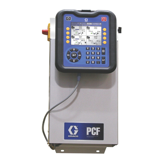
PCF
Precision Dispense System
Electronically-controlled fluid metering system that provides precise continuous flow of
single-component sealants and adhesives through closed-loop technology.
Not for use in explosive atmospheres.
For professional use only.
Important Safety Instructions
Read all warnings and instructions in this manual.
Save these instructions.
See page 4 for model information. See page 5 for
maximum working pressure and approvals.
313377B
ENG
Advertisement
Table of Contents
Troubleshooting

Related Manuals for Graco PCF


Summary of Contents for Graco PCF
- Page 1 Instructions - Parts 313377B Precision Dispense System Electronically-controlled fluid metering system that provides precise continuous flow of single-component sealants and adhesives through closed-loop technology. Not for use in explosive atmospheres. For professional use only. Important Safety Instructions Read all warnings and instructions in this manual. Save these instructions.
-
Page 2: Table Of Contents
Contents Related Manuals ......3 Operation ....... . 36 Models . -
Page 3: Related Manuals
Graco Standard Warranty ....108 Graco Information ......108... -
Page 4: Models
Check the identification (ID) plate for the 6-digit part number of the fluid metering system. Use the following matrix to define the construction of the system, based on the six digits. For example, Part PF1110 represents a PCF fluid ™... -
Page 5: Fluid Plate Assemblies
Models Fluid Plate Assemblies Includes: Maximum Working Pressure Flow Part psi (MPa, bar) Description Regulator Meter 24B958 6000 psi (41.4 MPa, 414 bar) Cartridge Regulator, 244734 246652 High Resolution Flow Meter 24B959 6000 psi (41.4 MPa, 414 bar) Cartridge Regulator, No Flow Meter 244734 24B960 5000 psi (34.4 MPa, 344 bar) -
Page 6: Warnings
Warnings Warnings The following warnings are for the setup, use, grounding, maintenance, and repair of this equipment. The exclama- tion point symbol alerts you to a general warning and the hazard symbol refers to procedure-specific risk. Refer back to these warnings. Additional, product-specific warnings may be found throughout the body of this manual where applicable. - Page 7 Warnings WARNING EQUIPMENT MISUSE HAZARD Misuse can cause death or serious injury. • Do not operate the unit when fatigued or under the influence of drugs or alcohol. • Do not exceed the maximum working pressure or temperature rating of the lowest rated system component.
-
Page 8: System Configurations
System Configurations System Configurations Typical Ambient System Installation Power Air Supply Drop Site . 1: Typical Ambient System Installation Key: *Control Center (User Interface) *CAN Cable *Fluid Plate Assembly G Fluid Supply System Applicator/Dispense Valve Fluid Supply Hose Sealer Automation Automation Controller Automation Communications Cable *Air Filter Assembly... -
Page 9: Typical Heated System Installation
System Configurations Typical Heated System Installation Power Air Supply Drop Site . 2: Typical Heated System Installation Key: AA *Control Center (User Interface) AG Heated Fluid Supply System AB *Fluid Plate Assembly AH Fluid Supply Hose AC Applicator/Dispense Valve AJ Heat Control AD Sealer Automation AK Automation Controller AE Automation Communications Cable... -
Page 10: Overview
System Components The PCF fluid metering system combines closed-loop The diagram in F . 3 shows an example of the PCF pressure control with the ability to change bead profiles module and cables. quickly. When used with the optional flow meter, the... -
Page 11: Fluid Plate Assembly Overview
Overview Fluid Plate Assembly Overview The PCF fluid regulator is electrically controlled by the PCF fluid control module. Consistent material flow is assured by a closed-loop pressure or closed-loop flow Fluid Plate Components control design. The module responds to automa-... - Page 12 Overview Fluid Regulator Fluid Control Module There are three fluid regulator options: NOTE: See LED Diagnostic Information, page 54, for • cartridge signal definitions. • ambient mastic Table 1: FCM Sensor Connections • heated mastic Connection Sensor Description All of the fluid regulator options use air pressure to con- Dispense solenoid trol fluid pressure, provide fast response to electronic Flow meter...
-
Page 13: Control Center Assembly Overview
Overview Control Center Assembly Overview Front View Side View Open View Gateway Module (24 Vdc Assembly) (100-240 Vac Assembly) . 6: Control Center Components The control center includes the following components: • Advanced Display Module (ADM) with USB; see • Gateway Module, which includes the following five page 14 for details. -
Page 14: User Interface/Display
Overview User Interface/Display TI12362a TI12363a . 7: User Interface Component Identification KEY: Callout Function Navigation Buttons Callout Function Navigate within a screen or to a new screen. Power On/Off Button Flat Panel Mount Enables/disables system. Mounts to control center bracket. System Status Indicator LED Model Number Tag Displays system status. -
Page 15: Communications Gateway Module
Overview Communications Gateway Module Front Back CC (see Fieldbus Connector Table) TI11972A TI11985A Fieldbus Connectors Table (C) DeviceNet PROFINET PROFIBUS EtherNet/IP TI11814A TI11815A TI11816A . 8: Communications Gateway Module Components Key: CA Communications Gateway Module CF Module Status LEDs (see LED Diagnostic Infor- CB Base mation, page 54) CC Fieldbus Connector... - Page 16 Overview Discrete Gateway Module Front Back r_24B681_2B9904_2b r_24B681_2B9904_1b . 9: Discrete Gateway Module Components Key: CB Base CD Module Connection Screws CE Access Cover CF Module Status LEDs (see LED Diagnostic Infor- mation, page 54) CH CAN Connectors CJ Discrete Gateway Module (DGM) CK D-Subminiature (D-Sub) Connector (see Appendix B - DGM Connection Details, page 93, for pinout details)
-
Page 17: Installation
Installation Before Installation Overview • Have all system and component documentation The basic steps to install a PCF system are shown available during installation. below. See the separate component manuals for detailed information. • See component manuals for specific data on compo- nent requirements. -
Page 18: Install Control Center
10.50 in. (267 mm) 5.75 in. (146 mm) Ensure the following criteria are met before mounting 17.00 in. (432 mm) the PCF control center: 16.25 in. (413 mm) • Select a location for the control center that allows adequate space for installation, service, and use of the equipment. - Page 19 1. Order the 255468 Light Tower Accessory as a diag- • Refer to your local code for the requirements for a nostic indicator for the PCF system. “true earth ground” in your area. 2. Connect the cable from the light tower to the digital NOTICE I/O port (BS) on the user interface.
-
Page 20: Install Fluid Plate Assembly
13.4 in. (340 mm) Before Mounting Assembly • See component manuals for specific information on component requirements. Information presented here pertains to the PCF fluid plate assembly only. • Have all system and subassembly documentation available during installation. • Be sure all accessories are adequately sized and pressure-rated to meet the system's requirements. - Page 21 No connection Splitter Assembly NOTE: Command cable inputs are not isolated from PCF 24 Vdc power. To turn on the dispense trigger, connect pin 3 (dis- pense trigger) to pin 5 (dispense trigger ground). . 14: Mount Breakout Kit 3.
- Page 22 The following are only general guidelines. • The PCF fluid plate assembly should be installed on the automation unit or in another appropriate place, as close as practical to the dispense valve. •...
-
Page 23: Install Cable Assemblies
Installation Install Cable Assemblies 1. Connect the CAN cable from the control center to 3. Connect power cable from power source to control the fluid plate assembly. center. 2. Connect the Gateway module to the automation controller. From Control Center (can use either connection) Power to ADM Power to FCM... -
Page 24: Install Communications Gateway Module Interface
Install Fieldbus Connections The Communications Gateway Module (CGM) provides Connect cables to fieldbus per fieldbus standards. a control link between the PCF system and a selected fieldbus. This provides the means for remote monitoring PROFINET and control by external automation systems. - Page 25 Installation Module Status (MS) EtherNet/IP State Description Comments Not initial- No power or module in Link ized “SETUP” or “NW_INIT” state Green Normal Diagnostic event(s) present operation TI11814A Flashing Initialized, Used by engineering tools to . 17: EtherNet/IP Fieldbus Connections Green diagnostic identify node on network...
- Page 26 Installation DeviceNet PROFIBUS 3 4 5 9 8 7 6 TI11815A TI11816A . 19: PROFIBUS Fieldbus Connections . 18: DeviceNet Fieldbus Connections Operation Mode (OP) Network Status (NS) State Description State Description Not online / No power Not online / No power Green On-line, data exchange Green...
-
Page 27: Install Discrete Gateway Module Interface
(123783). See Appendix B - DGM Con- The Discrete Gateway Module (DGM) provides a control nection Details, page 93, for details and pin link between the PCF system and an automation con- assignments. troller through discrete input and output connections. -
Page 28: System Setup
System Setup System Setup Overview System Setup The PCF system compensates for temperature, flow, or Configure Control pressure fluctuations. However, if there is a hardware Settings change on the supply system or the dispense material is changed, the PCF system must be setup again. -
Page 29: Configure Control Settings
System Setup Configure Control Settings select Gateway, Command Cable, or Display. Press to enter the value. Set the controls for the dispense source, how dispense commands are sent, and job settings. 7. Press to move to the Job End Mode field. 1. -
Page 30: Configure Mode Settings
System Setup Configure Mode Settings NOTE: The ability to dispense from multiple guns simultaneously is only allowed in either of the fol- lowing scenarios. Set gun commands, including the dispense mode (pres- sure, bead, shot, or full open) and flow rate or pressure •... -
Page 31: Configure Delay Settings
Configure Flow Meter Settings Set on and off delays (in milliseconds) for each gun and The accuracy of the PCF volume reporting depends on the regulator. For an explanation of the on and off precise adjustment of the K-factor(s). The fluid plate delays, refer to the On/Off Delays section on page 35. -
Page 32: Configure Pressure Loop Settings
See Verify Flow Meter Calibration, page 38, for instructions. Configure Pressure Loop Settings The PCF system uses variables (Kp and Ki) in the soft- ware calculations to accurately and precisely control the fluid pressure. NOTE: It is recommended that these values not be changed from the factory defaults of 32.00 for Kp... -
Page 33: Configure Errors
System Setup 5. Set the desired minimum and maximum pressure Configure Errors limits for the inlet, and the desired maximum pres- sure limit for the outlet. Set the error type (alarm or deviation) that will be issued if the pressure, flow rate, volume, or computed target 6. -
Page 34: Setup Maintenance Schedule/Parameters
Maintenance Setup Styles Advisory Limits screen (screen 7). The PCF system can store up to 255 styles. See Styles, page 41, for more information about styles and instruc- 3. Press to access the fields to make changes. -
Page 35: On/Off Delays
On/Off Delays . 29 and Table 6: Delay On/Off Timing show delay ON and OFF timing. The PCF fluid regulator can physically respond faster Table 6: Delay On/Off Timing than the dispense device and its solenoid. As a result, A Regulator ON... -
Page 36: Operation
3. Turn on air and electrical power to the system. press to turn the system on. 4. Turn on the main power to supply power to the PCF. 5. Check Interface Signals: If this is a new installa- 7. Press and hold . -
Page 37: Maintenance Mode Operation
Use maintenance mode to manually check the operation ing material at a maximum desired operating point. of the PCF system components before switching over to automation control (normal operation). See Dispense •... - Page 38 Operation Verify Flow Meter Calibration 3. Manually dispense material into the beaker. Hold the beaker so that the stream of material is sub- Most sealant and adhesive materials are compressible. merged in the captured material to minimize air Since the flow meter measures the material under high entrapment in the container.
- Page 39 Operation Dispense From Maintenance Screen 4. Press to move to the target fields. Enter the 1. Navigate to Home screen 1. target pressure, flow rate, and volume (dependent on control mode) and press to save. 5. Press to move to the gun check boxes. Press to select the desired guns.
-
Page 40: Automation Control (Normal) Operation
A job is initiated when the automation sends a Style alarms compare the measured volume to the target vol- Strobe signal to the PCF. Once the job is initiated, the ume for pressure mode. PCF will start tracking the amount of volume requested... -
Page 41: Styles
Operation Styles 2. Enter the style number in the Style field. The PCF system has the ability to handle up to 255 a. Press while in the Style Name field to styles, depending on the selected option. Styles typically correspond to different components of a specific sys- enter the Keyboard screen. -
Page 42: Typical Job Cycle
2. The robot sets the Style to the next desired style value. 3. The robot sets the Style Strobe to 1. 4. PCF reads the Style bits to select the new style. The system then starts a new job and sets Dispense In Process to 1. - Page 43 Operation Typical Job Cycle Chart 313377B...
- Page 44 Operation Control Charts Precharge (shaded = precharge active) Dispense Trigger Source = Command Cable * Dispense Gun X Open determined by Enable Guns check boxes on Fluid Plate Control Settings screen. 313377B...
- Page 45 Operation Control Charts (continued) Dispense Trigger Source = Gateway 313377B...
- Page 46 Operation Control Charts (continued) Dispense Trigger Source = Combined 313377B...
-
Page 47: Pressure Relief Procedure
Pressure Relief Procedure Pressure Relief Procedure 1. Shut off the fluid supply to the fluid plate assembly. Dispense Valve Air Solenoid 2. Place a waste container beneath the fluid drain valve under the filter. Place a waste container beneath the dispense valve. 3. -
Page 48: Shutdown
1. Press the Stop button (CC). 2. Shut off the material supply to the fluid plate/meter. 3. Follow the Startup on page 36. 4. Turn off the PCF system's compressed air supply. 5. Turn off the main power supply. TI12362a . -
Page 49: Usb Data
DOWNLOAD folder. related information to memory in the form of log files. PCF maintains three log files: job logs, error logs, and The error log maintains a record of the last 1,000 errors. dispense data logs. Follow the Download Procedure, Each error record in the log file contains: the date and page 50, to retrieve log files. -
Page 50: Custom Language File
File, and Upload Procedure sections. to be displayed within the user interface. The PCF system is able to display the following Unicode characters. For characters outside of this set, the sys- 2. The menu bar and USB indicator lights indicate that tem will display the Unicode replacement character, the USB is downloading files. -
Page 51: Upload Procedure
50, to automatically generate the proper folder structure on the USB flash drive. 9. Install USB flash drive into PCF system USB port. 2. Insert USB flash drive into USB port of computer. 10. The menu bar and USB indicator lights indicate that the USB is downloading files. -
Page 52: Troubleshooting
Troubleshooting Troubleshooting NOTE: Check all possible solutions in the chart Troubleshooting for individual regulators and flow below before you disassemble the system. meters is discussed in their separate manuals; refer to Related Manuals on page 3. Also refer to Error Codes and Troubleshooting, page 55, for detailed information on how error codes are communicated. -
Page 53: Fluid Meter
Troubleshooting Fluid Meter Problem Cause Solution No flow measurement Flow meter pick-up sensor loose Tighten flow meter pick-up sensor Flow too low Verify flow rate is above minimum for the flow meter selected Loose wiring Verify connection from flow meter to Damaged flow meter pick-up sensor Replace pick-up sensor False measurement... -
Page 54: Dispense Valves
Troubleshooting Dispense Valves Problem Cause Solution Valve not opening Air not getting to open port Verify air pressure solenoid No “Gun On” signal from automa- Check input from automation unit tion unit Valve not shutting off Air not getting to close port (except Verify air pressure to solenoid AutoPlus valve) Verify solenoid operation... -
Page 55: Errors
Errors Errors View Errors There are three levels of errors: alarms, deviations, and advisories. Alarms are critical and require immediate correction; therefore, the system automatically shuts When errors occur the highest priority active error is dis- down. Deviations are critical and require attention but played in the menu bar. - Page 56 Verify the key token is Error token required to run the installed system Verify the key token part number is correct for the PCF ADM WMC0 19 Display Error ADM error detected; Alarm Detected includes any error not covered by another...
- Page 57 (user select- Insufficient flow to Increase flow rate to requested minus the able) PCF regulator inlet regulator inlet allowed tolerance PCF regulator is not Incorrect style target regulating correctly volume or tolerance setting Check regulator; repair if necessary B1CX Low Computed...
- Page 58 Errors Error Gateway Error Code Error No. Error Name Description Error Type Cause Solution Fluid Plate Errors (continued) F6D1 Flow Meter Error Flow Meter error Alarm Problem detected with Verify flow meter is flow meter installed and/or con- nected correctly Replace if necessary WED1 V/P Error...
- Page 59 Errors Error Gateway Error Code Error No. Error Name Description Error Type Cause Solution Fluid Plate Errors (continued) WFD1 Flow Meter Operating mode Alarm or Selected gun mode Check gun mode set- Required requires flow meter. Advisory settings require flow tings Advisory is issued if (self-clearing)
- Page 60 Errors Error Gateway Error Code Error No. Error Name Description Error Type Cause Solution Fluid Plate Errors (continued) P3D1 High Pressure Measured outlet pres- Alarm or Incorrect limit set Verify limit is set cor- P4D1 sure greater than Deviation rectly desired outlet pressure (user select- Dispense hose/device...
- Page 61 Job Timer terminated by job timer used to stop shot dis- timed shot is desired pense EHD1 Purge Timer Purge timer expired Advisory PCF purge timer (style Automation control Expired 0) has expired requests purge EAC1 Maintenance Maintenance mode Advisory...
-
Page 62: Maintenance
Maintenance Maintenance Prior to performing any maintenance procedures, follow the Pressure Relief Procedure on page 47. Maintenance Schedule The following tables list the recommended maintenance procedures and frequencies to operate the equipment safely. The maintenance is divided between mechanical and electrical tasks. Maintenance must be performed by trained personnel per this schedule to assure safety and reliability of the equipment. -
Page 63: User Interface Display
Maintenance User Interface Display Upgrade Gateway Module Software Upgrade Software NOTE: The Gateway module connection to the sys- NOTE: Back up the custom language file (if tem is temporarily disabled during the installation of installed) before upgrading software. See USB Data, upgrade tokens. -
Page 64: Upgrade Cgm Map
Maintenance Upgrade CGM Map 4. Press and hold the push button for three seconds and then release. The red indicator light (CA) will flash twice, pause, and then once after the data map NOTE: The fieldbus connection is temporarily dis- abled during the upgrade of a map token. -
Page 65: Upgrade Fcm Software
Maintenance Upgrade FCM Software Air Filter Maintenance NOTE: The FCM connection is temporarily disabled To prevent filter element damage, replace air filter every during the installation of the upgrade a key token. two years or when pressure drop becomes 0.1 MPa (1.0 bar, 14.5 psi);... -
Page 66: Repair
Repair Repair Fluid Plate Assembly Repair Flow Meter For complete flow meter (129) repair instructions refer to the maintenance and repair section of manual 309834. Remove Flow Meter from Mounting Plate This section describes how to remove and replace com- 1. - Page 67 Repair Install Flow Meter on Mounting Plate 4. Remove the dispense valve solenoid (132) and replace it with a new solenoid. 1. Rest the flow meter (129) and bracket (124) on the fluid plate while threading the swivel fitting (109) onto the regulator material inlet.
- Page 68 Repair 5. Secure the new V/P valve to the bracket with Replace Fluid Control Module Base screws. 1. Prepare Fluid Plate Assembly for Repair, page 6. Reconnect the FCM cable and both air tubes. 2. Remove the FCM (103); follow Replace Fluid Con- Replace Fluid Control Module trol Module.
- Page 69 Repair Replace Transducer O-Rings 1. Prepare Fluid Plate Assembly for Repair, page 2. Remove the fluid outlet pressure sensor (117) from the regulator (108). r_pf0000_313377_16a . 50 3. Press the transducer (CG) out of the retainer nut (CH). 4. Remove the faulty o-ring (120) and replace with new.
- Page 70 Repair Repair Fluid Regulator NOTE: The retaining nut (CC) often loosens when removing the cartridge assembly from the base For complete cartridge fluid regulator repair refer to housing. Be sure to re-torque as described in step 4. instruction manual 308647. For complete mastic fluid regulator repair refer to instruction manual 307517.
-
Page 71: Control Center Assembly
Repair Control Center Assembly Replace Gateway Module Base 1. Prepare Control Center for Repair, page 71. 2. Remove the Gateway module (5); follow Replace Gateway Module. (Leave automation communica- tions cable (AE) attached to Gateway module.) Prepare Control Center for Repair 3. - Page 72 Repair Replace Advanced Display Module Replace Advanced Display Module Bracket 1. Prepare Control Center for Repair, page 71. 1. Prepare Control Center for Repair, page 71. 2. Remove the ADM (2); follow Replace Advanced 2. Disconnect the CAN cable (18) and the terminal Display Module.
- Page 73 Repair Replace DIN Rail Assembly 7. Reconnect all wiring to the din rail module, filter, and rocker/rotary switch. 1. Prepare Control Center for Repair, page 71. 8. Reassemble the line voltage assembly cover using 2. Remove both screws (22) and washers (28) from the screws and washers.
-
Page 74: Parts
Parts Parts Control Center Assembly Parts r_pf0000_313377_11a 24 Vdc Din Rail Assembly Shown Components of 24 Vdc Module Kit (24B929) and 100-240 Vac Line Voltage Module Kit r_pf0000_313377_10a (24B928) 313377B... - Page 75 Parts Control Center Assembly Parts Ref. Part Description Qty. 25✿ CLIP, speed, tubular Ref. Part Description Qty. 26✿ RIVET, aluminum COVER, rear 112925 SCREW, cap 289701 DISPLAY, with USB 100020 WASHER, lock 289697 BASE, cube 120999 RESISTOR, terminal 277674 ENCLOSURE, cube door 121901 SUPPRESSOR, box snap, ferrite MODULE, Gateway;...
-
Page 76: Fluid Plate Assembly Parts
Parts Fluid Plate Assembly Parts See page 78 135, 136 See page 77 See page 77 313377B... - Page 77 Parts Fluid Plate Assembly Parts (continued) 313377B...
- Page 78 Parts Fluid Plate Assembly Parts (continued) 117, 120 Fluid Plate 24A427 Shown 105, 117 140, 141, 150 313377B...
- Page 79 Parts Fluid Plate Assembly Parts Ref. Part Description Qty. 194337 WIRE, grounding, door Ref. Part Description Qty. 153▲ 186620 LABEL, ground PLATE, fluid 154✖ 107257 SCREW, hex, washer hd 289697 BASE, cube 155✓ SUPPRESSOR, box snap, ferrite 289696 FCM, cube 122610 ELBOW 277674 ENCLOSURE, cube door 159▲...
- Page 80 Parts Parts Varying by Assembly The following table lists the varying part numbers by fluid plate assembly, and the quantity for each assembly. Fluid Plate Assemblies Heated Mastic Cartridge Mastic Regulator Heated Regulator Cartridge Regulator Mastic with Heated Mastic with High Regulator with High Regulator...
-
Page 81: Appendix A - User Interface Display
It remains on while the ADM runs through initializa- tion and establishes communication with other modules The setup mode functions enable users to: in the PCF. • set units, adjust values, set formats, and view software information for each component;... - Page 82 Appendix A - User Interface Display System Mode Navigation within Screens The current system mode is displayed at the left of the Press to open drop-down menus on Setup menu bar. Alarm/Deviation screens. Also, press to enter changes or make a The current system error is displayed in the middle of selection.
-
Page 83: Setup Mode
Appendix A - User Interface Display Setup Mode Advanced Setup Screen 2 This screen enables users to setup the maintenance Setup mode screens are divided into four sections: units, and flow rate. advanced setup, Gateway setup, fluid plate setup, and style setup. - Page 84 There are two Gateway Setup screens, which enable users to set or change information regarding the Gate- way module used on the PCF system. These screens also enable users to view information regarding the par- ticular Gateway module used.
- Page 85 Gateway Setup Screen 3 - PROFINET See Gateway Setup Screen 2 - EtherNet/IP, page 84, for details. This screen enables users to view the following informa- tion regarding the Gateway module used on the PCF system: Gateway Setup Screen 1 - PROFINET •...
- Page 86 Appendix A - User Interface Display Fluid Plate Setup Screens Mode Settings Screen This screen enables users to set gun commands. Use There are seven fluid plate setup screens, which enable this screen to select a mode (pressure, bead, shot, or users to: full open) for each gun.
- Page 87 Appendix A - User Interface Display Delay Settings Screen Pressure Sensors Screen This screen enables users to set on and off delays (in NOTE: Inlet sensor settings will be grayed out on this screen for systems with heated fluid plates. milliseconds) for each gun and the regulator For an explanation of the on and off delays, refer to the On/Off...
- Page 88 Appendix A - User Interface Display Error Type Settings Screen Maintenance Advisory Limits Screen This screen enables users to set the error type (alarm or This screen enables users to set volume (or hours) limit deviation) that will be issued if the pressure, flow rate, that will trigger a maintenance advisory for the air sup- volume, or computed target goes outside the tolerance ply, V/P regulator, fluid regulator, flow meter, and all four...
- Page 89 Appendix A - User Interface Display Style Setup Screen Keyboard Screen Use all four arrow buttons to select each letter; press This screen enables users to set up to 256 styles. Press to access the style setup fields. Enter the style to enter the letter.
-
Page 90: Run Mode
Press to navigate through the Run mode screens. The PCF system has two operating modes: Home Screens There are two home screens: one for the fluid plate and • Dispense mode – enables the module to begin dis- pensing when it receives a command from the auto- one for the control center. - Page 91 Use the pressure control mode if the system does not include a flow meter. • Full Open Control – the PCF system does not con- trol fluid pressure or flow. Instead the regulator opens to allow for recirculation applications. Maintenance Mode...
- Page 92 Appendix A - User Interface Display Error Report Screens Maintenance Screen There are nine error report screens that display a chron- This screen enables users to view the maintenance ological list of system errors. These screens display the totalizers for each system component and the limits set last 140 errors.
-
Page 93: Appendix B - Dgm Connection Details
Appendix B - DGM Connection Details Appendix B - DGM Connection Details D-Sub Cable 123793 The cable length of the interface cable assembly 123793 is 50 ft (15.2 m). The following table identifies the cable interface signals. NOTE: See Appendix D - I/O Signal Descriptions, page 104, for I/O signal descriptions. D-Sub Wire Color Description... -
Page 94: D-Sub Cable 123792 And Breakout Board 123783
Appendix B - DGM Connection Details D-Sub Cable 123792 and Breakout Board 123783 The cable length of the interface cable assembly 123792 is 50 ft (15.2 m). The following table identifies the pin assignments for the 78-pin breakout board. NOTE: See Appendix D - I/O Signal Descriptions, page 104, for I/O signal descriptions. D-Sub Pin No. - Page 95 Appendix B - DGM Connection Details D-Sub Pin No. Description Pin Type Voltage (Vdc) Data 8192* Digital Out - Bank 3 0 - voltage connected to Pin 69 Data 16384* Digital Out - Bank 3 0 - voltage connected to Pin 69 Data 32768* Digital Out - Bank 3 0 - voltage connected to Pin 69...
- Page 96 Appendix B - DGM Connection Details Pin References NOTE: To avoid ground loops and noise immunity issues, do not ground the shield of the D-subminia- ture connector cable; it is already grounded through the mounting screw on the base of the DGM. .
-
Page 97: Digital Input
Appendix B - DGM Connection Details Digital Input The digital inputs function only when power is supplied to pin 51 and there is a ground connection to pin 70. See Pin References, page 96, for details. The digital input is rated at 0-30 Vdc, and requires an NEC Class 2 power supply connected to pin 51. -
Page 98: Digital Outputs
Appendix B - DGM Connection Details Digital Outputs The digital outputs function only when power is supplied to pins 27, 68, and 69 and there is a ground connection to pin 70. See Pin References, page 96, for details. The digital output is rated at 0-30 Vdc, and requires an NEC Class 2 power supply connected to pin 27 for supply bank 1, pin 69 for supply bank 2, and pin 68 for supply bank 3. -
Page 99: Analog Inputs
Appendix B - DGM Connection Details Analog Inputs The analog inputs function only when the DGM is connected to a power supply through the CAN connection. Each analog input has a corresponding reference (ground) pin. See Pin References, page 96, for details. Ω... -
Page 100: Appendix C - Cgm Connection Details
Appendix C - CGM Connection Details CGM I/O Data Map Byte Input Bit Description Dispensed Volume - 256 Dispensed Volume - 512 Automation Inputs (signals from PCF) Dispensed Volume - 1024 Byte Input Bit Description Dispensed Volume - 2048 Dispenser Ready... - Page 101 Appendix C - CGM Connection Details Byte Input Bit Description Byte Input Bit Description I160 Outlet Pressure - 1 I232 Flow Rate Command - 256 I161 Outlet Pressure - 2 I233 Flow Rate Command - 512 I162 Outlet Pressure - 4 I234 Flow Rate Command - 1024 I163...
- Page 102 Appendix C - CGM Connection Details Byte Input Bit Description I408-I415 I416-I423 I424-I431 I432-I439 I440-I447 313377B...
- Page 103 Appendix C - CGM Connection Details Automation Outputs (signals to PCF) Byte Output Bit Description O48-O55 Byte Output Bit Description O56-O63 Style - 1 Style - 2 O64-O71 Style - 4 O72-O79 Style - 8 O80-O87 Style - 16 O88-O95...
-
Page 104: Appendix D - I/O Signal Descriptions
Appendix D - I/O Signal Descriptions Appendix D - I/O Signal Descriptions Automation Inputs Dispenser Remote Start / Purge in Process This signal is 0 on power up. This signal will be 1 under the following conditions: Dispenser Ready This signal is 0 on power up. This signal will be 1 under •... -
Page 105: Automation Outputs
Appendix D - I/O Signal Descriptions Inlet Pressure Automation Outputs A 16 bit number indicates the current inlet pressure of the fluid plate. Applicable in all control modes. Units of Style this number are dependent on the pressure units. The desired style of the next job. These 8 bits are read at the start of a job to determine the selected style. -
Page 106: Technical Data
* Flow rates and viscosities are general estimates. Flow rates drop as viscosity increases. Fluids are expected to shear under pressure. New applications or fluids should always be tested to determine proper line sizes and equip- ment selections. See your Graco Authorized distributor for other capabilities. 313377B... -
Page 107: Fluid Plate Assembly Technical Data
Technical Data Fluid Plate Assembly Technical Data Mounting dimensions and parts breakdowns for the fluid plate assemblies are in the installation section of this man- ual. Cartridge Regulator Mastic Regulator Regulator Manual 308647 307517 Weight - No Flow Meter 25.5 lbs (11.6 kg) 33 lbs (15 kg) Weight - Helical 40 lbs (18 kg) -
Page 108: Graco Standard Warranty
With the exception of any special, extended, or limited warranty published by Graco, Graco will, for a period of twelve months from the date of sale, repair or replace any part of the equipment determined by Graco to be defective.