Graco PR70 Repair And Parts Manual
Two component liquid dispensing systems
Hide thumbs
Also See for PR70:
- Operation & maintenance manual (82 pages) ,
- Instructions - parts manual (74 pages) ,
- Repair parts (72 pages)
Table of Contents
Advertisement
Quick Links
Repair - Parts
PR70 and PR70v
Two Component Liquid Dispensing Systems
Fixed or variable ratio systems. For accurate metering, mixing, and dispensing of
two-component materials. For professional use only.
Not approved for use in European explosive atmosphere locations.
3000 psi (21 MPa, 207 bar) Maximum Working Pressure
100 psi (0.7 MPa, 7 bar) Maximum Air Inlet Pressure
Important Safety Instructions
Read all warnings and instructions in all
supplied manuals. Save these instructions.
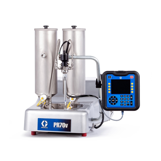
PR70v Shown with Advanced Display Module
312760Y
EN
ti12385b
Advertisement
Table of Contents

Related Manuals for Graco PR70


Summary of Contents for Graco PR70
- Page 1 Repair - Parts PR70 and PR70v 312760Y Two Component Liquid Dispensing Systems Fixed or variable ratio systems. For accurate metering, mixing, and dispensing of two-component materials. For professional use only. Not approved for use in European explosive atmosphere locations. 3000 psi (21 MPa, 207 bar) Maximum Working Pressure 100 psi (0.7 MPa, 7 bar) Maximum Air Inlet Pressure...
-
Page 2: Table Of Contents
Repair ........29 Graco Information ......82 HydraCheck Kit Installation . -
Page 3: Related Manuals
Related Manuals Related Manuals PR70 and PR70v Operation and Parts Manuals Part Description 3A0429 ™ PR70 with Standard Display Module Operation and Maintenance Manual 312759 ™ PR70 and PR70v with Advanced Display Module Operation and Maintenance Manual 312394 PR70 and PR70v Feed Systems Manual... -
Page 4: Product Configurator
PR7F - J - A5 - A5 - E - A6 - A6 - 3 - 1 - 2 - A - N - 3 - N - H - N - 6 - N - N Code: The following part number fields apply for the PR70 and PR70v part numbering configurator fields. Shaded items listed in the configurator table below are “Super Standard” items that are typically stocked and provide the best deliv- ery dates. - Page 5 Product Configurator High Volume Side Piston and Code E Part Low Volume Side Piston Size (mm Code B Part Metering Tube Material 80, Available in Nylon Only LC1___ Nylon Piston, Stainless Steel Metering 100, Available in Nylon Only Tube (last three digits of part number is 120, Available in Nylon Only the mm piston size)
- Page 6 Product Configurator LC0814 3/4 in. (19 mm) - 15 ft (4.6 m) LC0182 Recirculating, Off-Board Tanks, 3/8 in. (9.5 mm) - 10 ft (3.0 m) LC0881 Heated, 1/4 in. (6.5 mm) - 2.5 ft (0.6 m) LC0183 Recirculating, Off-Board Tanks, LC0882 Heated, 1/4 in.
- Page 7 Product Configurator LC0210 Recirculating, Heated, Off-Board LC0444 High Pressure, Recirculating, Tanks, 3/4 in. (19 mm) - 10 ft (3.0 m) On-Board Tanks, 1/2 in. (13 mm) - 10 ft (3.0 m) LC0211 Recirculating, Heated, Off-Board Tanks, 3/4 in. (19 mm) - 15 ft (4.6 m) LC0445 High Pressure, Recirculating, On-Board Tanks,...
- Page 8 Product Configurator LC0313 One 1.0 gpm Flow Meter, One 0.5 gpm Code L Part Mixer Type Flow Meter, With Pressure Transduc- None LC0063 3/16 in. (4.8 mm) x 32 LC0317 Two 2.0 gpm Flow Meters, With Pres- LC0057 1/4 in. (6.4 mm) x 24 sure Transducers LC0058 3/8 in.
- Page 9 When ordering tanks for spare or LC0255 7.5 L, Stainless Steel, 240V Heat, replacement parts, refer to Parts sec- with Shut-Off Valve tion of the PR70 and PR70v Feed Sys- tems manual. LC0054 30 L, Stainless Steel LC0259 30 L, Stainless Steel, 240V Heat...
- Page 10 Part Off-Board Tank Stands Fill Port None LC0142 Off-Board Pneumatic Agitator - 30 L LC0103 PR70 Tank Stand LC0143 Off-Board Pneumatic Agitator - 60 L LC0247 PR70v Tank Stand LC0146 Off-Board Vacuum De-gas, Pneumatic Agitator, Fill Port, Slinger - 30 L...
-
Page 11: Warnings
Warnings Warnings The following warnings are for the setup, use, grounding, maintenance, and repair of this equipment. The exclama- tion point symbol alerts you to a general warning and the hazard symbol refers to procedure-specific risk. Refer back to these warnings. Additional, product-specific warnings may be found throughout the body of this manual where applicable. - Page 12 Warnings WARNING FIRE AND EXPLOSION HAZARD Flammable fumes, such as solvent and paint fumes, in work area can ignite or explode. To help prevent fire and explosion: • Use equipment only in well ventilated area. • Eliminate all ignition sources; such as pilot lights, cigarettes, portable electric lamps, and plastic drop cloths (potential static arc).
-
Page 13: Moisture Sensitivity Of Isocyanates
Never store ISO in an open container. • The PR70 has exposed shafts, so extra precautions must be taken when using ISO Materials. Make sure that the shafts are wiped clean and lubricated if sit- ting unused for any length of time, such as overnight shutdowns. -
Page 14: Grounding
Grounding Grounding 5. Press the system air pressure relief switch down to stop air supply and to vent air pressure in the machine. It is the yellow tab at the left, rear of the machine. The hole in the tab should be visible. 6. - Page 15 Shutdown 3. Place a container below the dispense valve and activate a small shot to flush mixed material out of the valve. 4. Relieve pressure. See Pressure Relief Procedure. 5. With a clean rag and cotton swabs, clean the end of the dispense valve.
-
Page 16: Troubleshooting
Troubleshooting Troubleshooting Before starting any troubleshooting procedures, perform 3. Allow the machine to cool if the machine has a heat the following procedure. control option. Try the recommended solutions in the order given for 1. Relieve pressure. See Pressure Relief Procedure, each problem to avoid unnecessary repairs. - Page 17 Troubleshooting Problem Cause Solution Material dispensed not correct weight Specific gravity of one or more of the Recalibrate machine. two materials has changed since cali- bration Machine air pressure has changed Readjust air pressure regulator to since calibration. value used when machine was cali- brated, or recalibrate machine.
-
Page 18: (Advanced Display Module)
Troubleshooting Error Codes (Advanced Display Module) Code-Class-Event System Shown on Errors Screen Description Behavior Ref 050X-A-Improper System Cal Improper Calibration 06CX-A-Invalid Key Token No or Invalid Key Token A401-A-Over Current Z1 Heater Over Current, Zone #1 A402-A-Over Current Z2 Heater Over Current, Zone #2 A403-A-Over Current Z3 Heater Over Current, Zone #3 A404-A-Over Current Z4... - Page 19 Troubleshooting Code-Class-Event System Shown on Errors Screen Description Behavior Ref F2B-Low Flow B Side Low B Side Fluid Flow, relative to calibra- tion and user-input allowable variance. F2FX-D-Delta Velocity Minus Delta Velocity Minus F3FX-D-Delta Velocity Plus Delta Velocity Plus F6A-Flow Meter A Problem Flow Meter A Problem, or bad connection between Fluid Control Module and Flow Meter A...
- Page 20 Troubleshooting Code-Class-Event System Shown on Errors Screen Description Behavior Ref T203-D-Low Material Temp Z3 Material Below Temperature, Zone #3 T204-D-Low Material Temp Z4 Material Below Temperature, Zone #4 T401-A-High Material Temp Z1 Material Over Temperature, Zone #1 T402-A-High Material Temp Z2 Material Over Temperature, Zone #2 T403-A-High Material Temp Z3 Material Over Temperature, Zone #3...
- Page 21 Troubleshooting Code-Class-Event System Shown on Errors Screen Description Behavior Ref WM02-A-Current Fault Z2 High Relay 1 Current, Zone #2 WM03-A-Current Fault Z3 High Relay 1 Current, Zone #3 WM04-A-Current Fault Z4 High Relay 1 Current, Zone #4 WMC1-A-Control Fault Z1 Unexpected Relay 1 Current, Zone #1 WMC2-A-Control Fault Z2 Unexpected Relay 1 Current, Zone #2...
- Page 22 Troubleshooting System Behavior Reference System Behavior Description When this error is generated, a pop-up with the error-code will be shown until it is acknowledged by pressing the Enter button ( ). Any auto-sequencing in progress will be stopped, and the foot switch will be disabled until the error-code is acknowledged.
-
Page 23: Error Codes (Standard Display Module)
Troubleshooting Error Codes Key: A Error Code Animation Field (Standard Display Module) B Error Code Number Field D Error Code ICON When the machine is operating and a fault is detected, it E Error Code Acknowledgement ICON will report the condition by generating an error code. Error codes are typically generated when the machine is When an error code is generated, the user will need to idle after dispensing a shot. - Page 24 Troubleshooting Error Code Title Cause, Details ICON Less than User has requested a shot < the minimum allowable size entered during Minimum Shot calibration. (< 15% of stoke, N/A in Operator Mode). Requested Error Improper The calibration done on the machine is invalid, so the requested shot Calibration Error cannot be executed.
-
Page 25: Electrical Schematics
Electrical Schematics Electrical Schematics NOTE: Fluid Control Module #2 sections apply only to models with optional features purchased. See F See F See F . 3: Electrical Schematic - Page 1 312760Y... - Page 26 Electrical Schematics . 4: Electrical Schematic - Page 2 312760Y...
- Page 27 Electrical Schematics . 5: Electrical Schematic - Page 3 312760Y...
- Page 28 Electrical Schematics NOTE: See PR70 operation manual for Optional External Control Interface instructions. Customer Supplied Dry Contact/Relay Brown SHOT SEL - BIT 0 Gray SHOT SEL - BIT 3 Black Not Used NOTE: Connector #2 is for use with systems with an Advanced...
-
Page 29: Repair
Repair Repair HydraCheck Kit Installation 200d 200c 200b 200a ti12437a Torque to 85 in-lb (9.6 N•m). . 7: HydraCheck Installation - Variable Ratio Base 100d 100b ti12436a . 8: HydraCheck Installation - Fixed Ratio Base 312760Y... - Page 30 Repair Install Adjustment Screw/Cap The following procedure is the same for Fixed and Variable Ratio bases, except where noted. See F 7 and F . 8 for part references. See Kits on page 77 for kit numbers. NOTE: The HydraCheck kit is intended to be used with 9.
-
Page 31: Air Cylinder Kit Installation
Repair Air Cylinder Kit Installation ti12490a Torque to 41 in-lb (4.6 N•m). Torque to 350 in-lb (39.5 N•m). Torque to 100 ft-lb (135 N•m). Coat all sliding surfaces with lubricant, part 115982. Apply sealant tape to npt fittings. Disassemble the Air Cylinder See Kits on page 77 for kit numbers. - Page 32 Repair 10. Partially remove the air cylinder by pulling on the 21. Reinstall the four long screws (404) that attach the cylinder from the back of the machine until the air two drive blocks (417, 418) by finger-tightening lines at the elbow fittings can be seen. them.
-
Page 33: Rear Pump Rebuild Kit Installation
Repair Rear Pump Rebuild Kit Installation See Kits on page 77 for kit numbers. The pump shaft is installed with Krytox. Contact with Krytox can lead to flu-like symptoms. The MSDS for this material is available upon request. ti12491a Torque to 350 in-lb (39.5 N•m). Lube shaft with krytox grease prior to insertion into bearing. - Page 34 Repair 6. Remove the shroud (117, 214). See F . 16 on 16. Apply one layer of thin masking tape over the male page 42 and F . 21 on page 48. threads of the pump shaft that mates with the drive block.
-
Page 35: Piston/Cylinder Replacement Kit Installation
Repair Piston/Cylinder Replacement Kit 7. Push the drive block (104, AA) forward until pistons are fully extended. See F . 7 and F . 8 on Installation page 29. 8. Use a wrench to prevent the pump shaft (511) from See Piston Package on page 58 and Nylon and rotating and remove the piston screw (605). -
Page 36: Check Valve Rebuild Kit Installation
Repair Check Valve Rebuild Kit 8. Remove the existing check valve (514) from the housing by inserting a screwdriver or dowel rod into Installation the female threaded end of the check valve housing (513). See Pump Sub-Assembly, LC0112, page 53 for 9. -
Page 37: Piston Plug Installation
Piston Plug Installation Pressure Transducer Installation NOTE: The pressure transducers are designed to work with the hoses available in the PR70 configurator. If they are used with other hoses, unexpected alarms may occur. 1. Follow steps 1 through 6 of Piston Plug Installa- 1802 tion on this page. -
Page 38: Flow Meter Installation
Repair Flow Meter Installation 9. Install fluid lines into fitting (2003) on top of flow meter. 1. Drain the pump. 10. For side A flow meters, plug flow meter sensor • If ball valves are installed, close the ball cable into port #1 on Fluid Control Module #2. valves then take several shots. -
Page 39: Fluid Control Module Replacement
Repair Fluid Control Module If there is only one fluid control module on the Replacement machine, the module number is 1. If there are two fluid control modules, the mod- 1. Remove access cover (D). ule closest to the air regulator is module number 1 and the other module is number 2. -
Page 40: Fuse Replacement
Repair Fuse Replacement 7. If there is only one fluid control module on the machine, set the rotary switch (S) to 1. See F . 14. If there are two fluid control modules, set the rotary switch (S) to 1 on the module closest to the air regulator and set the rotary switch (S) to 2 on the other module. -
Page 41: Parts
Parts Parts See Feed Systems manual for feed system parts. See Related Manuals on page 3. Fixed Ratio Base, LC0262, LC0263, LC0264, LC0265 100d 100b Torque to 85 in-lb (9.6 N•m). Torque to 350 in-lb (39.5 N•m). Torque to air cylinder shaft to100 ft-lb (135 N•m). - Page 42 Parts Fixed Ratio Base, continued 100c 100a Torque to 85 in-lb (9.6 N•m). ti12487a Torque to 350 in-lb (39.5 N•m). Retaining ring must rest against pump body. 117a ti12476b . 16 312760Y...
- Page 43 Parts Part Description 100a 120920 SHOCK ABSORB, adjustable (models LC0263 and LC0265 only) 100b 120919 NUT, hex (models LC0263 and LC0265 only) 100c 111260 SCREW, set, cup point (models LC0263 and LC0265 only) 100d 15K816 CAP, adjustment, Hydracheck (models LC0263 and LC0265 only) 101 LC0112 PUMP, sub-assembly 102 120913...
-
Page 44: Fixed Ratio Frame Sub-Assembly, Lc0290
Parts Fixed Ratio Frame Sub-Assembly, LC0290 2205 2206 2204 2202 2201 2203 2202 2207 ti12572a Apply anti-seize compound (part 073025) to screws. . 17 Part Description 2201 120599 PIN, dowel 2202 120913 SCREW 2203 15K788 FRAME, base, machined 2204 LC0234 SENSOR, assembly 2205 120918... -
Page 45: Fixed Ratio Drive Block Assembly, Lc0107
Parts Fixed Ratio Drive Block Assembly, LC0107 2306 2301 2305 2308 2302 2307 2309 2305 2303 2304 ti12573a Apply grease (part 115982) to all internal parts. Tighten retaining nut until alignment rod (2302) cannot be moved. Loosen retaining nut until alignment rod can move side-to-side with no in-and-out movement. -
Page 46: Lc0245
Parts Variable Ratio Base, LC0242, LC0243, LC0244, LC0245 200d 200c 200b 200a ti12437a Torque to 85 in-lb (9.6 N•m). Torque to 350 in-lb (39.5 N•m). Torque to air cylinder shaft to100 ft-lb (135 N•m). ti12488b Torque to 85 in-lb (9.6 N•m). . - Page 47 Parts Variable Ratio Base continued 214a ti12475b . 20 Part Description Part Description 61/2906-BK/11 HOSE, 0.245ID x 0.375 OD, PU, 95 200a 120920 SHOCK ABSORB, adjustable (models LC0243 and LC0245 only) LC0246 SHIELD, assembly 200b 111260 SCREW, set, cup point 214a LABEL, shield 15M511...
-
Page 48: Variable Ratio Frame Sub-Assembly, Lc0232
Parts Variable Ratio Frame Sub-Assembly, LC0232 2406 2409 2430 2409 2404 2404 2406 2409 2416 2417 ti12568a 2436 2427 2415 2405 2401 2426 2418 ti12569a 2432 Drive Block Rear Parts Torque screws to 140 in-lb (15.8 N•m). Torque to 8 in-lb (0.9 N•m). Torque screws to 350 in-lb (39.5 N•m). - Page 49 Parts Variable Ratio Frame Sub-Assembly continued 2407 2424 2410 2425 2425 2435 2403 2413 2429 2421 2402 2414 2434 2419 2413 2412 2421 2420 2411 2403 2422 2424 2412 2407 Drive Block Front/Side Parts ti12571a 2428 2414 2423 2435 2425 2425 2411 Torque screws to 140 in-lb (15.8 N•m).
- Page 50 Parts Part Description Part Description 2421 15K868 WASHER, female, male modi- 2401 119912 SCREW, machined, phillips fied, assembly pan head 2422 15T377 BAR, ratio, beam 2402 107596 SCREW, cap, hex head 2423 15T383 PIN, pivot, beam, ratio 2403 116193 PIN, dowel, 1/4 x 3/4 2424 15T384 PLATE, guide, ratio...
-
Page 51: Air Cylinder, Lc0110, Lc0111, Lc0230, Lc0231
Parts Air Cylinder, LC0110, LC0111, LC0230, LC0231 NOTICE The four long screws (404) that attach the two drive blocks (417, 418) must be tightened in a crisscross pattern. Failure to do so may result in air cylinder damage. ti12490a 409† Torque to 41 in-lb (4.6 N•m). - Page 52 Parts Part Description 107571 PACKING, o-ring 114100 SCREW, cap, socket hd 120875 O-RING, 3 in. (assemblies LC0110 and LC0230) 104131 O-RING, 4.5 in. (assemblies LC0111 and LC0231) 120880 SCREW 120881 BEARING 120884 SCREW 120899 VALVE, solenoid, 3 way 120900 VALVE, solenoid, 3 way 409 †...
-
Page 53: Pump Sub-Assembly, Lc0112
Parts Pump Sub-Assembly, LC0112 The pump shaft is installed with Krytox. Contact with Krytox can lead to flu-like symptoms. The MSDS for this material is available upon request. ti12491a Torque to 350 in-lb (39.5 N•m). Lube shaft with krytox grease prior to insertion into bearing. Shaft seal (503) must be installed with open side facing the washer (512). - Page 54 Parts Check Valve, Assembly LC0093 2104 2101 2102 ti12565a 2103 Chamfer The side of the seat with an outside diameter chamfer must point away from the ball. Part Description 2101 105445 BALL, 0.5000 2102 121084 SPRING 2103 15D312 BUSHING, ball guide 2104 196832 SEAT, lapped 312760Y...
-
Page 55: Control Bracket, Lc0240, Lc0261
Parts Control Bracket, LC0240, LC0261 2513 2510 2508 2507 2506 2512 2511 2509 2505 2502 2501 2503 2504 ti12568b Assembly Apply thread sealant tape to male npt threads. Part Description Part Description 2507 289697 BASE, Fluid Control Module 2501 15T735 BRACKET, control mounting 2508 121583 HARNESS, I/O, M12 x M8 x sub- (assembly LC0240 only) -
Page 56: Incoming Power Bracket, Lc0239
Parts Incoming Power Bracket, LC0239 Part of Ground from Ground from Ground from 306, 318 ti17531b Apply thread sealant tape if applicable. Vent direction must point toward machine. 312760Y... - Page 57 Parts Ref Part Description Ref Part Description 318 81/1054-4/11 FUSE, type f, 4 amp, 250v, 301 119912 SCREW, mach. phillips pan fast 319 LC0291 CABLE, power, assembly 302 121018 FITTING, elbow, male, 325 * 84/2725-1/11 LABEL, symbol, CE swivel, 1/4 npt 326 121558 CONNECTOR, power, panel 303 120876...
-
Page 58: Piston Package
Parts Piston Package ti12438a Arrow on cylinder must point to the o-ring (606) on the right. Nylon Piston, Stainless Steel Metering Tube Assemblies Reference Number and Description 603† Piston Tube, Nylon Ring, support, Package pump Piston Washer piston Screw O-ring LC1080 LCC080 LCB080... - Page 59 Parts UHMW Piston, Stainless Steel Metering Tube Assemblies Reference Number and Description 603† Piston Tube, UHMW Ring, support, Package pump Piston Washer piston Screw O-ring LC2160 LCC160 LCA160 LC2180 LCC180 LCA180 LC2200 LCC200 LCA200 LC2220 LCC220 LCA220 15M099 15K887 LC2240 LCC240 LCA240 LC2260...
- Page 60 Parts UHMW Piston, Ceramic Metering Tube Assemblies NOTE: The UHMW piston, ceramic metering tube assemblies contain a carbide ball. This ball replaces the standard check valve ball in pump assembly LC0112. If a UHMW piston, ceramic metering tube assembly needs to be installed, replace the original ball in pump assem- bly LC0112 with the ball included with the pump pack- age.
-
Page 61: Nylon And Uhmw Piston Replacement Kits
Parts Nylon and UHMW Piston Replacement Kits Piston Sizes 080-119 Piston Sizes 160-960 Piston Sizes 120-159 When ordering a UHMW replacement kit, the following Part Description numbering applies: PISTON SCREW LCE - 160 O-RING Code: When ordering a piston replacement kit, the following intelligent part numbering system applies for Nylon based pistons. -
Page 62: Controls
Parts Controls Fluid Control Module There are three options for controls. • Advanced Display Module with one Fluid Control Module, LC0274 • Advanced Display Module with two Fluid Control Modules, LC0275 • Standard Display Module with one Fluid Control Module, LC0272 ti12711b Part Description... -
Page 63: Applicator Mounting
Parts Applicator Mounting Assemblies with Upper Clamp Assemblies with Base Clamp ti21830a Part Description Part Description 96/0045/98 WASHER, lock, split, 5/16 in., 16P082 BASE, arm, mounting stainless steel (assemblies 16P409 BLOCK, mounting, front 256438 and LC0293 only) 16P550 BLOCK, mounting, rear 120913 SCREW (assemblies 256438 121194... -
Page 64: Dispense Valve
Parts Dispense Valve Standard Dispense Valves, 255179 and 255181 See MD2 manual for parts information. See Related Manuals on page 3. Gun Mounted MD2 Valves, LC0120 and LC0122 901a 901b Assembly LC0120 Shown ti12440a Part Description LC0006 VALVE, assembly, 10:1, gun, electric (assembly LC0122 only) LC0004 VALVE, assembly, 1:1, gun, electric... - Page 65 Parts Lever Actuated MD2 Valves, LC0121 and LC0123 1101a 1101b 1103 1102 Assembly LC0121 Shown ti12441a Part Description 1101 LC0005 VALVE, assembly, 1:1, lever, electric (assembly LC0121 only) LC0007 VALVE, assembly, 10:1, lever, electric (assembly LC0123 only) 1101a 255249 LEVER, 2K dispense valve 1101b †...
-
Page 66: Mixers
Parts Mixers 1301 1303 1302 Assembly LC0061 Shown ti12442a Reference Number and Description 1301 1302 1303 Mixer Package Description Mixer Shroud Sleeve LC0057 1/4 in. X 24 60/0204/50 94/0883-C/98 LC0058 3/8 in. x 24 60/0200/50 94/0883-D/98 LC0059 3/8 in. x 36 60/0201/50 94/0883-E/98 LC0060... -
Page 67: Hose Packages
Parts Hose Packages Unheated, Non-Recirculating Hoses 1404 1403 1401 1402 Assembly LC0801 Shown ti12446a Apply thread sealant tape to male npt threads before assembly. Reference Number and Description 1401 1402 1403 1404 Hose Package Description Hose Assembly 90 Deg Elbow Adapter Bushing LC0801... - Page 68 Parts Unheated, Recirculating Hose Packages 1603 1602 1603 1602 1601 Assembly LC0161 shown installed as the Low Volume and High Volume Side Hose Package 1601 ti12444a Apply thread sealant tape to male npt threads before assembly. Dispense valve shown for reference only. Reference Number and Description 1601 1602...
- Page 69 Parts Reference Number and Description 1601 1602 1603 1604 1605 Hose Valve Supply Hose Return Hose Pressure Package Description Assembly Assembly Assembly Sensor O-Ring LC0434 3/8 in. x 180 in., on-board, 255975 LC0410 LC0418 16A093 111457 high pressure LC0170 1/2 in. x 30 in., on-board 255974 255992 258064...
- Page 70 Parts Heated, Recirculating Hose Packages 1702 1703 1704 1702 1703 1701 1705 Assembly LC0190 shown installed as the Low Volume and High Volume 1701 Side Hose Package ti12443b Apply thread sealant tape to male npt threads before assembly. Dispense valve shown for reference only. Reference Number and Description 1701 1702...
- Page 71 Parts Reference Number and Description 1701 1702 1703 1704 1705 Heated Insulated Hose Valve Supply Hose Return Hose Pressure Package Description Assembly Assembly Assembly Sensor O-Ring LC0474 3/8 in. x 180 in., on-board, 255975 258089 LC0458 16A093 111457 high pressure LC0196 1/2 in.
- Page 72 Parts Heated, Non-Recirculating Hoses 1503 1504 1501 1502 Part LC0881 Shown ti12445a Apply thread sealant tape to male npt threads before assembly. Reference Number and Description 1501 1502 1503 1504 * 1505 * 1506 Heated Hose 90 Degree 45 Degree Circuit Extension Hose Package Description...
-
Page 73: Power Cords
Parts Power Cords ti12447a Part 121054 Shown Power Cord Package Description 121054 CORD SET, 250V, 10A, United States 121055 CORD SET, 250V, 10A, North America 121056 CORD SET, 250V, 10A, Continental Europe 121057 CORD SET, 250V, 10A, United Kingdom/Ire- land 121058 CORD SET, 250V, 10A, Israel 121060... -
Page 74: Flow Monitoring
Parts Flow Monitoring Part Number and Quantity Flow Meters Flow Pressure Monitoring 0.5 gpm, 1.0 gpm, 2.0 gpm, Transducer, Pump Plug, Package LC0299 LC0300 LC0301 257433 LC0041 LC0302 LC0303 LC0304 LC0305 LC0306 LC0307 LC0312 LC0313 LC0314 LC0315 LC0316 LC0317 Pump Plug, Assembly LC0041 Pressure Transducer, Assembly 257433 1802 1902... - Page 75 Parts Flow Meters 2005 2004 2001 2003 ti13390a 2002 0.5 gpm Flow 1.0 gpm Flow 2.0 gpm Flow Meter Assy, Meter Assy, Meter Assy, Description LC0299 LC0300 LC0301 2001 METER, flow 121932 121933 121934 2002 SENSOR, meter, flow 121909 2003 ADAPTER, reducer 94/0745/98 2004 FITTING, nipple, hex 121907...
-
Page 76: Tank Stands, Assemblies Lc0247 And Lc0103
Parts Tank Stands, Assemblies Heat Zone Assemblies LC0247 and LC0103 See Integrated Heat manual referenced at the begin- ning of this manual for Heat Zone Assemblies parts information. 2001 2002 ti12473a Assembly LC0247 Shown Part Description 2001 121097 FASTENER, u-bolt with mounting plate 2002 15U373 SUPPORT, tank stand, variable ratio (assembly LC0247 only) -
Page 77: Kits
Kits Kits Mixer and Shroud Options Machine Rebuild Kits Part Description Part Description LC0063 Mixer, 3/16 in. (6.5 mm) x 32, 10 Mixers LC0091 3.0 in. Air Cylinder rebuild kit with shroud LC0092 4.5 in. Air Cylinder rebuild kit LC0057 Mixer, 1/4 in. - Page 78 Kits Vacuum Kits Refill Kits These vacuum kits contain the parts necessary to attach Refill Kits 256659 and 256660 are designed to turn on a vacuum pump to the tanks. and off a transfer pump as needed to keep the tanks at the proper fluid level.
-
Page 79: Dimensions
Dimensions Dimensions Machine with On-Board Tanks ti12621b ti12622b PR70 † Assembly Dimensions, in. (mm) Polyethylene Tanks Stainless Steel Tanks 7.5 L, No 7.5 L, with No Agitators With Agitators Agitators Agitators 26.4 (670) 38.6 (980) 28.2 (716) 38.2 (970) 39.9 (1013) -
Page 80: Machine With Off-Board Tanks
Dimensions Machine with Off-Board Tanks ti12624c ti12623c PR70 † Assembly Dimensions, in. (mm) 30 L Tank 60 L Tank No Agitators With Agitators No Agitators With Agitators 75.7 (1923) 83.4 (2118) 64.9 (1648) 89.5 (2273) 32.1 (815) 32.1 (815) 32.1 (815) 32.1 (815) -
Page 81: Technical Data
Technical Data Technical Data Metering Pump Effective Area ..... 80 to 960 mm (0.124 to 1.49 in. ) per side Small Air Cylinder Effective Area . -
Page 82: Graco Standard Warranty
With the exception of any special, extended, or limited warranty published by Graco, Graco will, for a period of twelve months from the date of sale, repair or replace any part of the equipment determined by Graco to be defective.