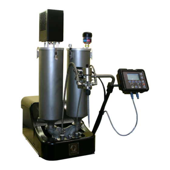
Graco PR70 Series Operation And Maintenance Manual
2 component liquid dispensing system
Hide thumbs
Also See for PR70 Series:
- Operation & maintenance manual (82 pages) ,
- Repair and parts manual (82 pages) ,
- Instructions - parts manual (74 pages)
Table of Contents
Advertisement
Quick Links
Operation and Maintenance
TM
PR70
2 Component
Liquid Dispensing Systems
PR70 All Models
100 PSI (0.7 Mpa, 7 bar) Maximum Air Inlet Pressure
For Dispensing Multi-part Sealants and Adhesives
Not Designed for Use in Explosive Atmospheres
Important Safety
Instructions
Read all warnings and
instructions in this
manual.
GRACO OHIO INC.
8400 PORT JACKSON AVE. NW, NORTH CANTON, OH 44720-5464
Phone: 330.966.3000 Fax: 330.966.3006
LiquidControlService@graco.com
Copyright 2007, Graco Inc is a registered to I.S. EN ISO 9001
PROVEN QUALITY, LEADING TECHNOLOGY.
www.liquidcontrol.com
LiquidControlParts@graco.com
312393C
Advertisement
Table of Contents

Related Manuals for Graco PR70 Series


Summary of Contents for Graco PR70 Series
- Page 1 Read all warnings and instructions in this manual. PROVEN QUALITY, LEADING TECHNOLOGY. GRACO OHIO INC. 8400 PORT JACKSON AVE. NW, NORTH CANTON, OH 44720-5464 Phone: 330.966.3000 Fax: 330.966.3006 www.liquidcontrol.com LiquidControlService@graco.com LiquidControlParts@graco.com Copyright 2007, Graco Inc is a registered to I.S. EN ISO 9001...
-
Page 2: Table Of Contents
Technical Data......... 50 Shot Size Definition (M2)......19 Dimensions..........51 Ratio Checks ........... 19 Graco Ohio Standard Warranty ..... 52 Miscellaneous Machine Setups ..... 20 Manual Control Options (M1).......20 Purge Timer / Alarm Settings (M2) ......20 Cycle Counter and Silent Mode Control (M3) ..21 Date and Time Settings (M4) .......22... -
Page 3: Models
Models Models A PR70 system can be ordered with many different options from the configurator below. The example PR70 system part number illustrated below contains the highlighted choices from the charts on pages 3 - 6. PR70 - 2 - BT - BF - A - A7 - A4 - 2 - 3 - 1 - 1 - N - 2 - N - N - N - 2 - N - N - N Code : The following configuration P/N was assigned to the machine shipped with this manual: PR70-... - Page 4 Models 2007 Product Configurator - PR70 (Continued) Code F Check Valve Standard Check Valve High Volume Hose Low Volume Hose 3/16" (4.8mm) - 2.5' (0.6m) 3/16" (4.8mm) - 2.5' (0.6m) 3/16" (4.8mm) - 10' (3.0m) 3/16" (4.8mm) - 10' (3.0m) 3/16"...
- Page 5 Models Code P High Volume Tank Code Q High Volume Tank Cover (cont’d) None 1-1/2" (38mm)NPT FLANGE, No Tanks Off-board Pneumatic Agitate SST - 60L 8L, Twin PE Tanks (High and Low Volumes) and Lid Off-board Pneumatic Vacuum Degas & Agitate SST - 30L 8L one 120 VAC 50/60 Hz agitator Off-board Pneumatic Vacuum Degas &...
-
Page 6: Pr70 Accessories
Models 2007 Product Configurator – PR70 (Continued) Code T Low Level Sensor Options Code V Wet Test Wet Test (Note: Material must be supplied; No None Dealer/Distributor discounts apply) PE Tanks No Wet Test Steel Tanks On-Board Code W Off-Board Tank Stands Steel Tanks Off-Board None, or NA Steel Tanks 1 On / 1 Off-board... -
Page 7: Supplied Manuals
Manuals Supplied Manuals The following manuals will be supplied with the PR70 Operation PR70. Refer to these documents for detailed machine Part Description information. 312393 Manual, Operation & Maintenance PR70 PR70 Feed System Part Description 312394 Manual, Tank/Feed System, PR70 Dispense Valve, MD2 Part Description... -
Page 8: Warnings
• Ground equipment, personnel, object being sprayed, and conductive objects in work area. See Grounding instructions. • Use only Graco grounded hoses. • Check gun resistance daily. • If there is static sparking or you feel a shock, stop operation immediately. Do not use equipment until you identify and correct the problem. - Page 9 Warnings WARNING EQUIPMENT MISUSE HAZARD Misuse can cause death or serious injury. • Do not operate the unit when fatigued or under the influence of drugs or alcohol. • Do not exceed the maximum working pressure or temperature rating of the lowest rated system component.
-
Page 10: Installation
General Information Verify the location has access to compressed air, AC power and is well ventilated. Accessories are available from Graco. Make certain all accessories are adequately sized and pressure-rated to 2. Place the PR70 onto the designated location. Allow meet your system needs. -
Page 11: Component Identification
Component Identification Component Identification Key: Dispense Valve (DV) HMI (Human Machine Interface) Static Mixer Shield Locking Screw Power Switch Air Filter G Customer Input Receptacle Protective Shield Air Pressure Regulator Ball Valve (Optional) A and B Tanks (Onboard, Polyethylene versions illustrated). Figure 2: Typical PR70 (Back View, without Hoses) Key: Pump Assembly... -
Page 12: Hmi Control And Indicators
Component Identification Key: Drive Block Hydracheck (optional) Check Valve Cylinder (Metering Tube) Rear Bearing Phase Adjustment Screw/Locking G Mounting Hole in Base Frame Figure 4: PR70 Top View with Shield, Tanks, DV and HMI Removed. HMI Control and Indicators Figure 5: PR70 HMI Controls Key: Screen, Display Area Operator Mode ICON... -
Page 13: Hmi Main Run Screen
Run Screens HMI Main Run Screen Figure 6: Typical PR70 Main Run Screen (Shot and Operator Modes) Respectively) Key: Shot Number Field (“x” in Operator Mode) F Cycle Counter Shot Size Field (“XXXXXX” in Operator Mode) G DV status Field Shot weight/mass unit of measure (Grams). -
Page 14: Machine Disable Mode (" "Red)
Disable Mode, Entering Set-up Screens 2. To enter the calibration screens, press . To Machine Disable Mode (“ ”red) enter the maintenance screens, press . Refer to Figure 9 for a screen navigation diagram. Setup Screens with Passwords Enabled 1. From the Run screen press . - Page 15 Screen Layout Figure 9: PR70 Screen Navigation Diagram 312393C 15 of 52...
-
Page 16: Machine Priming
Priming and Calibration Machine Priming Before the machine can be properly calibrated with material, it will need to be primed. Be careful not to pinch fingers when manually moving the machine drive block. Piston Position Calibration (C1) Read all manufacturer’s warning and material MSDS to know the This step should be executed the 1 time the machine specific hazards of the material used. -
Page 17: Phasing (C2)
Priming and Calibration 10. The machine pistons should extend slowly until they 1. Select the location where the piston will reverse encounter the cylinder entrance and a number (from the extend to retract motion) by pressing between 1600 to 1900 should appear for ‘H’. keys. -
Page 18: Machine Calibration Shots (C4)
Priming and Calibration From the Run screen, press , then press , then press 3 times. The following screen will be displayed. Figure 13: Open Dispense Valve (ODV) Screen (C3) Key: A Current ODV Adjustment (in mm from the cylinder Figure 14: Stroke Calibration (CAL) Screen (C4) entrance). -
Page 19: Shot Size Definition (M2)
Priming and Calibration Screen Number (M2). 12. Press to arm the machine to take a long CAL & keys will navigate to adjacent screens. shots. The icon will be highlighted (“ ”). Press to de-arm the machine. 1. Press . The following screen will be displayed: 13. -
Page 20: Miscellaneous Machine Setups
Priming and Calibration 6. Place an empty container on a scale, and tare 9. After the material is dispensed, place each (zero) the scale. Repeat the process with a 2 container on the same scale, and measure the net container on a 2 scale. -
Page 21: Cycle Counter And Silent Mode Control (M3)
Miscellaneous Machine Setups 3. Press to accept the value or to retain the From the Run screen, press , then press , and then previous value. press 2 times. The following screen will be displayed. Figure 19: M2 after Purge Shot Size Prompt Figure 21: M3 Cycle Counter and Silent Mode Control 4. -
Page 22: Date And Time Settings (M4)
Miscellaneous Machine Setups Date and Time Settings (M4) 1. Press . The M4 screen will appear as follows. At the bottom right corner of the Run screen the date is shown in DD-MM-YY format and the time is shown in HH:MM, 24 hour format. -
Page 23: Password Setup / Clearing (C5)
Miscellaneous Machine Setups E Change Level ICON Screen Number (C6) & keys will navigate to adjacent screens. To turn the Tank Level Sensors On/Off: 1. Press 2. Press to accept the change or to retain the previous setting. Figure 26: Tank Level and (C6) 3. -
Page 24: Setting/Clearing A Maintenance Only Password:24
Password Setting/Clearing 3. Press to accept. 4. Re-enter the same 6-digit number. 5. Press to accept. 6. If both 6-digit passwords match, the C5 screen will be displayed, and an “OK” after the second row of symbols. If the 2 numbers do not match, the Figure 30: Administrative Password Entry with NO process will need to be repeated. -
Page 25: Miscellaneous Machine Features
Hibernate and Demo Modes If the press and hold does not start Miscellaneous Machine Features immediately after the animation sequence, or the press and hold is interrupted, the previous and this step may need to be HMI Hibernate Mode repeated. To help preserve the life of the HMI backlight, the HMI will enter a Hibernate mode after the machine 4. -
Page 26: Pressure Relief Procedure
Pressure Relief and Shutdown Procedures, Error Codes Pressure Relief Procedure With the machine in an idle state: 1. If the machine pistons are not fully retracted, retract the pistons by pressing in the M1 screen. See Figure 17. 2. Manually open the dispense valve by pressing the third M1 soft key until the “... -
Page 27: Error Code Table
Error Code Table Error Code Table Title Cause, Details ICON Stuck Key Error A key on membrane has been active (pressed) for > 30 seconds continuously. Replace the HMI. This error code does not require user acknowledgment and will clear itself automatically if the condition is removed. Communication The Display module has lost communication with the Fluid Control Module. - Page 28 Error Code Table Low Material Both tanks are low (only generated if tank sensing is enabled). Fill both tanks Level, Both Tanks with material. Alarm or Error Tank level errors will be generated after every shot if the condition still exists. Bad Linear There is a fault with the linear position sensor.
-
Page 29: Icon Descriptions
ICON Tables ICON Descriptions Key Description Screen Maintenance and Calibration Screens Enter / Exit. Shot Mode / Operator Control Mode Selection. Run, C2, (green) Shot Request Red Stop or Cancel (Stops Operation Immediately, regardless of Screen). Up (Used to Raise Numerical Entry, Screen Navigation or Shot Selection). Many Down (Used to Lower Numerical Entry, Screen Navigation or Shot Selection). - Page 30 ICON Tables ICON Description Screen Short Stroke Calibration Shot Long Stroke Calibration Shot Administrative Password Set/Clear Maintenance Only Screens Password Set/Clear Tank Level Sensing ON Tank Level Sensing OFF Delta Velocity Set Level (0 = OFF) Displacement Valve Always Open Displacement Valve Always Closed Displacement Valve Automatic Operation Shot Size Definition...
-
Page 31: Maintenance
The PR70 Fluid control module (FCM) contains a blue When software in the HMI or Fluid Control Module run token, installed in the socket provided. It has (FCM) needs updating, a black Graco update token is identical appearance to the black programming token, used. -
Page 32: Troubleshooting
Troubleshooting Troubleshooting 3. Allow the machine to cool, if the machine has a heat control option. Try the recommended solutions in the order given for the each problem to avoid unnecessary repairs. Also Before starting any troubleshooting procedures: verify all circuit breakers, switches, and controls are 1. -
Page 33: Repair
Base Frame and Air Cylinder Assemblies Repair Major Mechanical Assemblies, and Attachments Figure 38: PR70 Top View w/o Tanks with Footswitch and HMI Illustrated Figure 39: PR70 Base Frame to Air Cylinder, Pump and Drive Block Attachments Key: Description Description LC0112 Pump Assembly, PR70 LC0107... -
Page 34: Base Frame Assembly
Base Frame and Air Cylinder Assemblies Figure 40: PR70 Power Entry Bracket and Control Bracket Assembly Attachments Key: Description Description 120885 Screw, SHC, M5 – 0.8 x 14 LC0106 Power Entry Assembly, PR70 LC0108 Control Bracket Assembly, PR70 120885 Screw, SHC, M5 – 0.8 x 14 Base Frame Assembly Figure 41: PR70 Base Frame Assembly (LC0109) Key:... -
Page 35: Air Cylinder Assemblies, And Rebuild Kits
Base Frame and Air Cylinder Assemblies Air Cylinder Assemblies, and Rebuild Kits Figure 42: PR70 Air Cylinder System and Schematic 312393C 35 of 52... - Page 36 Air Cylinder Assemblies Figure 43: PR70 Air Cylinder Assemblies, 3.0” & 4.5” Diameters (LC0110 & LC0111) Key: (LC0110, 3.0” DIA. Assy., PR70) (LC0111, 4.5” DIA. Assy., PR70) Description Description 107571 ORING, VIT, BAD 107571 ORING,VIT,BAD 114100 SCREW, SHC, M4X0.7X55, MS, E 114100 SCREW, SHC, M4X0.
- Page 37 2 attachment screws (4 of Figure 40). 13. Install Graco high temperature lubricant Grease (Graco P/N 115982) to the inside of the tube (16), 3. Remove the 2 air valves (items 7 & 8) from the the outside of the piston (19), all the orings and the cylinder end block (18) by removing the 3 cylinder rod (20).
-
Page 38: Drive Block Assembly
Pump Assembly Drive Block Assembly Figure 45: PR70 Drive Block Assembly (LC0107) Key: Description Description 120891 SCREW, SHS, M6-1.0 X 8, MS 15K805 BLOCK, DRIVE, PR70S 15K801 ROD, ALIGNMENT 15K868 WASHER, SPERICAL, ½ DIA. MODIFIED 15K802 NUT, RETAINER 84/0130- LABEL, HAND CRUSH, 1.3 X 1.1, TRIANGLE, 27/11 Pump Assemblies and Rebuild Kits Figure 46: PR70 Pump Assembly (LC0112) - Page 39 Pump Assembly Key: Description Description 106258 ORING, VIT, JCB 15K803 COLLAR, PUMP 108712 NUT, HEX, M8 X 1.25, MS 15K804 HOUSING, BEARING, SEAL, PR70S 120887 POSIPAK, 0.375ID X 0.625OD, COIL 15K824 SHAFT, PISTON, 3/8, PR70S, SS 120890 RING, RET, INT, 1.00, SS 15K828 WASHER, SEAL, 3/8, PR70S, SS 120982...
- Page 40 18. Instigate several shot to fill the pump with new from the bearing housing. material. 8. Apply new high temperature grease lubricant (Graco 19. Re-calibrate and re-phase the machine, due to the P/N 115982) to the inside of the pump bearing procedure performed.
-
Page 41: Piston Cylinders Or Metering Tubes
Pistons & Metering Tubes Piston Cylinders or Metering Tubes Figure 49 PR70 Nylon and UHMWPE Piston Replacement Kits Key: Description Description Piston Oring Screw To install a new Piston or Piston/Cylinder When ordering a piston replacement kit, the following Replacement Kit: intelligent part numbering system applies for Nylon based pistons: 1. - Page 42 M1 screen. 10. To prevent machine movement, press (red). 11. Lubricate the new orings with a high temperature grease, Graco P/N 115982 or equivalent. Place the lubricated orings into the inside circle placements in the pump housing and pump end caps.
- Page 43 (item 8 of figure 46) with a wrench. Remove the existing Oring (2). 4. Lubricate the new Oring with a high temperature grease, Graco P/N 115982 or equivalent. Place the Figure 51 PR70 Piston Plug Assemby lubricated Oring into the cap location of the end cap.
-
Page 44: Hose Assemblies
Hose Assemblies Hose Assemblies Figure 52 Piston to DV Hose Assemblies Figure 53 Heated Piston to DV Hose Assemblies 312393C 44 of 52... -
Page 45: Miscellaneous Mechanical Assemblies
Miscellaneous Assemblies Miscellaneous Mechanical Assemblies Figure 54: PR70 Power Entry Bracket Assembly (LC0106) Key: Description Description 119912 SCREW, PAN, M3X6, PHILLIPS, SS 84/0130-26/11 LABEL, PE 121018 ELBOW, SWVL, 3/8 X ¼ NPT, FXM, 90DE LC0034 HARNESS, WIRE, REMOTE SIGNAL 120876 PWR SUPPLY, 24VDC, 40W, 100-240VAC IN 121178 VALVE, LOCKOUT, ¼... - Page 46 Miscellaneous Assemblies Figure 55: PR70 Control Bracket Assembly (LC0108) Key: Description Description 84/0153-1/89 CLAMP, HARNESS, REUSEABLE, 5/8,NYL 121019 ELBOW, SWVL, 3/8 X 3/8 NPT, FXM, 90DE 120885 SCREW, SHC, M5-0.8 X 14, MS, E LC0124 CONTROLLER, FCM 120897 REGULATOR, 100PSI, 3/8NPT, GAGE 15K797 BRACKET, ELECTRICAL, 120954...
- Page 47 Miscellaneous Assemblies Key: Description Description 15G581 PLATE, NAME, VALVE COVER, P3 15K628 LABEL, PR70 120060 CLIP, SPEED TUBULAR 15M511 LABEL, WARNING, PR70 15K806 SHIELD, PR70S Figure 57: PR70 Hydracheck Components Figure 58: PR70 HMI Components Key: Description Description 288446 Display Module, PR70 120999 Termination Plug 255235...
-
Page 48: Wiring Diagrams
Wirin g Diagrams Wiring Diagrams Figure 59: PR70 Wiring Interconnect Illustration 312393C 48 of 52... - Page 49 Wirin g Diagrams Figure 60: Wiring Diagram, PR70 312393C 49 of 52...
-
Page 50: Technical Data
Tech nical Data Technical Data Category Data Metering Pump Effective Area 80 – 960 mm (0.124 – 1.49 in ) per side Small Air Cylinder Effective Area 4560 mm (7.07 in Large Air Cylinder Effective Area 10260 mm (15.9 in Maximum Stroke Length 38.1 mm (1.50 in) Minimum Stroke Length... -
Page 51: Dimensions
Technical Data Dimensions Figure 36: PR70 Dimensions (ON-Board PE Tank version Illustrated) A typical PR70 Machine, with the standard On-Board twin 8 liter PE Tanks has the following dimensions: Dimension In. (mm) Dimension In. (mm) A (width) 18.49 (469.6) C (depth) 30.62 (777.7) B (height) 26.39 (670.3) -
Page 52: Graco Ohio Standard Warranty
OTHERS. Graco Ohio Inc. 8400 Port Jackson Ave NW N. Canton, OH 44720 Phone (330) 966-3000 Fax (330) 966-3006 Send e-mail for technical support to: LiquidControlService@Graco.com Send e-mail for parts orders to: LiquidControlParts@Graco.com Web Site: www.LiquidControl.com 312393C 52 of 52...