Table of Contents
Advertisement
Quick Links
Operation - Parts
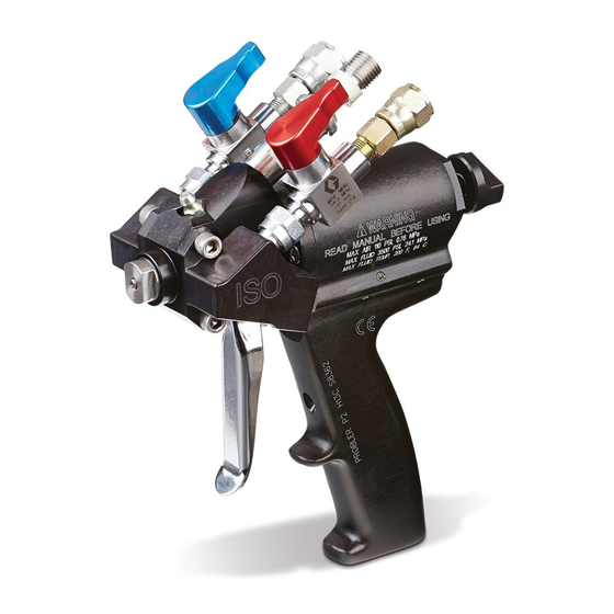
Auto Probler
Dispense Gun
For automated dispensing of non-flammable, two-component foam and polyurea
materials. For professional use only.
Not approved for use in explosive atmospheres or hazardous locations.
Models:
GCP4RA
GCP4R0
GCP4R1
GCP4R2
GCP4R3
GCP4R4
GCP4R5
24X636
See page 3 for model information, including working
pressure and approvals.
Important Safety Instructions
Read all warnings and instructions in this
manual before using this equipment. Save
these instructions.
®
P2
313267W
EN
Advertisement
Table of Contents

Related Manuals for Graco Auto Probler P2


Summary of Contents for Graco Auto Probler P2
- Page 1 Operation - Parts ® Auto Probler 313267W Dispense Gun For automated dispensing of non-flammable, two-component foam and polyurea materials. For professional use only. Not approved for use in explosive atmospheres or hazardous locations. Models: GCP4RA GCP4R0 GCP4R1 GCP4R2 GCP4R3 GCP4R4 GCP4R5 24X636 See page 3 for model information, including working...
-
Page 2: Table Of Contents
Technical Specifications ....29 Graco Standard Warranty ....30... -
Page 3: Models
Models Models Maximum Static Fluid Air inlet Pressure Range Pressure Part No. Description* psi (MPa, bar) psi (MPa, bar) Approvals GCP4RA Gun, P2, Automatic, .036 in. GCP4R0 Gun, P2, Automatic, .051 in. GCP4R1 Gun, P2, Automatic, .059 in. GCP4R2 Gun, P2, Automatic, .073 in. 90-110 psi (0.62-0.76 MPa, GCP4R3 Gun, P2, Automatic, .088 in. -
Page 4: Warnings
Warnings Warnings The following warnings are for the setup, use, grounding, maintenance, and repair of this equipment. The exclama- tion point symbol alerts you to a general warning and the hazard symbols refer to procedure-specific risks. When these symbols appear in the body of this manual or on warning labels, refer back to these Warnings. Product-specific hazard symbols and warnings not covered in this section may appear throughout the body of this manual where applicable. - Page 5 Warnings WARNING BURN HAZARD Equipment surfaces and fluid that is heated can become very hot during operation. To avoid severe burns: • Do not touch hot fluid or equipment. FIRE AND EXPLOSION HAZARD Flammable fumes, such as solvent and paint fumes, in work area can ignite or explode. Paint or sol- vent flowing through the equipment can cause static sparking.
-
Page 6: Important Isocyanate (Iso) Information
Important Isocyanate (ISO) Information Important Isocyanate (ISO) Information Isocyanates (ISO) are catalysts used in two component materials. Isocyanate Conditions Spraying or dispensing fluids that contain isocyanates creates potentially harmful mists, vapors, and atomized particulates. • Read and understand the fluid manufacturer’s warnings and Safety Data Sheets (SDSs) to know specific haz- ards and precautions related to isocyanates. -
Page 7: Material Self-Ignition
Important Isocyanate (ISO) Information Material Self-ignition NOTE: The amount of film formation and rate of crystal- lization varies depending on the blend of ISO, the humidity, and the temperature. Foam Resins with 245 fa Some materials may become self-igniting if applied too Blowing Agents thick. -
Page 8: Component Identification
Component Identification Component Identification . 1: Auto Probler P2 Component ID Key: Isocyanate (ISO) Hose Connection Polyol Hose Connection Supply Air Hose Connection Supply Air Switch Isocyanate Shutoff Valve Polyol Shutoff Valve Piston Lock System Air Off Port System Air On Port... -
Page 9: Installation
Pressure Relief Procedure described on page 13 3. Remove the air hose from the supply air switch (D). before connecting the Auto Probler P2 gun to the feed The supply air switch fitting is 1/4 in. NPSM. system equipment. -
Page 10: Operation
How the Auto P2 Gun Works The Auto Probler P2 is designed to be mounted on a robotic arm or other automated equipment connected to The P2 is designed and manufactured to operate at a a feed system. -
Page 11: Piston Lock
Operation Piston Lock Valve Control The flow of material into the mixing chamber is con- trolled by the on or off position of the two material shut- off valves (E,F). High-pressure fluid from dispensing devices can NOTE: Both material shutoff valves must be fully open pierce skin. -
Page 12: Spray Technique
To achieve the optimum spray pattern for other applica- tions, appropriate mixing chambers are available from Graco in seven round and six flat spray sizes. See Kits on page 22. NOTE: Foam rise and cure times vary according to the material and substrate temperature. -
Page 13: Maintenance
Maintenance Maintenance NOTE: Letters in parenthesis used in this section refer 7. If you suspect the spray tip or hose is clogged or to the callouts in Component Identification on page 8. that pressure has not been fully relieved: a. Very slowly loosen each material hose (A,B) Pressure Relief Procedure end coupling, one at a time, to relieve pressure gradually. -
Page 14: Check The Material Valves For Leaks
Maintenance Check the Material Valves for Check Side Blocks Leaks 1. Turn off both material shutoff valves (E,F). Before conducting any maintenance or removing the side blocks, follow the Pressure Relief Procedure to help prevent serious injury. Make sure that both mate- rial valves are in the off position. -
Page 15: Daily Shutdown
Maintenance 3. Examine the sides of the mixing chamber for 7. Reassemble the side blocks (K) and tighten the scratches and/or material buildup. Carefully, without screws. Grease should appear at the tip of the mix- scratching the seal surfaces, remove any accumu- ing chamber. -
Page 16: Daily Startup
Maintenance Daily Startup 4. Pull the slide valve on the supply air switch halfway back to limit the air purge. 1. Clean the snout insert. Be sure both the face and bottom flat are clean. Drill out the snout bore with the correct size bit for the snout. -
Page 17: Routine Care
Maintenance Piston Lock Adjustment and 6. Inspect all parts for wear or damage and replace as required with new genuine Graco replacement parts Installation Procedure from your authorized Graco distributor. 7. Inspect all threads for wear or damage and replace as required. -
Page 18: Verify The Piston Lock Assembly Is Working
Refer to information included in this Maintenance sec- tion to troubleshoot problems. For additional information or technical assistance, contact Graco Ohio Technical 6. Place the side seal housing in the gun head so the Assistance at 800-746-1334 or Ohio TA@graco.com. -
Page 19: Parts
Apply amber oil. Torque to 45-50 in-lbs (5-5.6 N•m). Apply blue sealant to threads. Apply LocQuic Primer T on item (43), then apply Loctite 222 Sealant if replacing screws 17 14 . 2: Auto Probler P2 Parts - All Models 313267W... - Page 20 Parts Quantity by Model Ref Part Description 117634 SWIVEL, union, no #6 jic 117635 SWIVEL, union 117724 O-RING GC0128 SWITCH, assy, switch, air GC0259 BALL, 1/4 dia, 302 sst GC0498 FITTING, connector 100846 FITTING, lubtn, st GC1898 PISTON, air, 1-3/8, probler 2 24Z770 KIT, piston, p2, alum pist, ss GC1899...
- Page 21 Parts Quantity by Model Ref Part Description GC251A KIT, insert, mix, chamber, aa GC2510 KIT, insert, mix, chamber, 00 GC2511 KIT, insert, mix, chamber, 01 GC2512 KIT, insert, mix, chamber, 02 GC2513 KIT, insert, mix, chamber, 03 GC2514 KIT, insert, mix, chamber, 04 GC2515 KIT, insert, mix, chamber, 05 17P754...
-
Page 22: Kits
Kits Kits Air Cap Kits 258761 and 24Z769 NOTE: Refer to Parts on page 19. Apply red sealant and torque to 35-40 in-lbs (4-4.5 N•m). Apply a liberal coating of lithium grease to seals and surfaces specified. Apply blue sealant to threads. Adjust nut counter-clockwise until it bottoms out. -
Page 23: Service And Repair Kits
Kits Service and Repair Kits GC1937 Standard Repair Kit GC194 Hardware Kit -AA Part Description Quantity Part Description Quantity C20988 O-Ring GC0082 Drill Bit GC2056 O-Ring GC0081 Drill Bit 110242 O-Ring GC0086 3/16 in. Ball Driver 106555 O-Ring GC0087 5/32 in. Ball Driver GC2057 O-Ring GC0175... -
Page 24: Bulk Kits
248279, 4 oz (113 gram) [10] 248128 O-Ring GC2394 Adapter Fitting High adhesion, water resistant, lithium-based lubricant. SDS sheet available at www.graco.com. 258762, Piston Lock Repair Kit Grease Cartridge for Gun Shutdown Part Description Quantity 248280 Cartridge, 3 oz (85 gram) [10]... -
Page 25: Static Mixer Kit - Gc1956
Kits Static Mixer Kit - GC1956 GC0331 GC0257 117517 GC2335 16V976 GC0408 GC1955 Airless tip (See page 27) GC1956, Static Mixer Kit Part Description Quantity GC2335 Fluid Nozzle Seal 16V976 GC0257 Nozzle Nut GC0331 Plug Fitting GC0480 Spiral Mixing Element 117517 O-ring GC1955... -
Page 26: Cleaning Drill Chart
Cleaning Drill Chart Cleaning Drill Chart Round Mixing Mixing Chamber Nozzle Mixing Chamber Hole Chamber Cleaning Drill Cleaning Drill GC250A 248891 0.033 276984 0.022 GC2500 GC0083 0.049 GC0080 0.035 GC2501 249112 0.057 246629 0.042 GC2502 GC0069 0.071 256628 0.052 GC2503 246625 0.086 246627... - Page 27 Cleaning Drill Chart Spacer Seals Use only brown series C spacer seals with series B spray tips. Failure to do so may result in material clog- ging. Series C Spacer Seals (Brown) Short Version Long Version Use with tips LPA2-147-1525 Use with tips LPA2-147-4325 through LPA2-147-3850 through LPA2-147-7250...
-
Page 28: Auto P2 Spray Options
Auto P2 Spray Options Auto P2 Spray Options Standard Round Spray Air Cap GC1938 Standard Flat Spray Kit Configuration Airless tip (See page 27) Pour Configuration Jet Stream Configuration P2 Auto Spray Options Part Description 17F253 Gun Head GC250X Mix Chamber Body GC251X Mix Chamber Insert 117517... -
Page 29: Technical Specifications
Technical Specifications Technical Specifications Auto Probler P2 Metric Maximum Static Fluid Pressure 3500 psi 24.1 MPa, 241 bar Air Inlet Pressure Range* 90-110 psi 0.62-0.76 MPa, 6.2-7.6 bar Air Inlet Size 1/4-18 NPSM Inlet Size A 5 JIC, 1/2-20 UNF... -
Page 30: Graco Standard Warranty
With the exception of any special, extended, or limited warranty published by Graco, Graco will, for a period of twelve months from the date of sale, repair or replace any part of the equipment determined by Graco to be defective.