Table of Contents
Advertisement
Advertisement
Table of Contents

Related Manuals for Cisco ESW 500


Summary of Contents for Cisco ESW 500
- Page 1 ADMINISTRATION GUIDE Cisco Small Business Pro ESW 500 Series Switches...
- Page 2 © 2009 Cisco Systems, Inc. All rights reserved. OL-19128-01...
-
Page 3: Table Of Contents
Chapter 2: Managing Device Information ESW 500 Series Switches Administration Guide Introduction Typical Installation Methods Default Configuration settings on the ESW 500 Series Switches Physical Connectivity Connecting to the Switch Using the Default Static IP Address Using a Dynamic IP Address Allocated to the Switch By DHCP... - Page 4 Chapter 3: Managing Smart Ports Chapter 4: Configuring System Time Chapter 5: Configuring Device Security ESW 500 Series Switches Administration Guide Help Defining System Information Viewing Device Health Resetting the Device Managing Cisco Discovery Protocol Defining the Bonjour Discovery Protocol...
- Page 5 ESW 500 Series Switches Administration Guide Mapping Authentication Profiles Defining TACACS+ Modifying TACACS+ Settings Defining RADIUS Modifying RADIUS Server Settings Defining Access Methods Defining Access Profiles Defining Profile Rules Modifying Profile Rules Defining Traffic Control Defining Storm Control Modifying Storm Control...
- Page 6 Chapter 6: Configuring Ports Chapter 7: Configuring VLANs ESW 500 Series Switches Administration Guide Defining Martian Addresses Defining DHCP Snooping Defining DHCP Snooping Properties Defining DHCP Snooping on VLANs Defining Trusted Interfaces Binding Addresses to the DHCP Snooping Database Query By...
- Page 7 Chapter 8: Configuring IP Information Chapter 9: Defining Address Tables Chapter 10: Configuring Multicast Forwarding ESW 500 Series Switches Administration Guide Assigning Ports to Multiple VLANs Defining Interface Settings Modifying VLAN Interface Settings Defining GVRP Settings Modifying GVRP Settings Defining Protocol Groups...
- Page 8 Chapter 11: Configuring Spanning Tree Chapter 12: Configuring Quality of Service ESW 500 Series Switches Administration Guide Modifying a Multicast Group Defining Multicast Forwarding Modifying Multicast Forwarding Defining Unregistered Multicast Settings Defining STP Properties Global Settings Defining Spanning Tree Interface Settings...
- Page 9 Chapter 13: Configuring SNMP ESW 500 Series Switches Administration Guide Configuring Bandwidth Modifying Bandwidth Settings Configuring VLAN Rate Limit Modifying the VLAN Rate Limit Defining Advanced QoS Mode Configuring DSCP Mapping Defining Class Mapping Defining Aggregate Policer Modifying QoS Aggregate Policer...
- Page 10 Chapter 14: Managing System Files Chapter 15: Managing Power-over-Ethernet Devices Chapter 16: Managing System Logs Chapter 17: Viewing Statistics ESW 500 Series Switches Administration Guide Modifying SNMP Notifications Defining SNMP Filter Settings Managing Cisco Discovery Protocol Software Upgrade Save Configuration...
- Page 11 Chapter 18: Aggregating Ports Chapter 19: Managing Device Diagnostics ESW 500 Series Switches Administration Guide Resetting GVRP Statistics Counters Viewing EAP Statistics Managing RMON Statistics Viewing RMON Statistics Resetting RMON Statistics Counters Configuring RMON History Defining RMON History Control Viewing the RMON History Table...
-
Page 12: Chapter 1: Getting Started
Getting Started Introduction Thank you for choosing the Cisco Small Business Pro ESW 500 Series Switch. The ESW 500 series is a family of Ethernet switches that addresses network infrastructure and access needs of small business customers for voice, data, PCs, Servers, and video applications. -
Page 13: Typical Installation Methods
The following diagram illustrates three common installation scenarios: In the first two scenarios, called VOICE and SECURITY DATA, you are adding an ESW 500 switch to a new or existing Cisco Smart Business Communications Systems (SBCS) network deployment. This deployment is either a VOICE network with UC520 being the anchor device or SECURITY / DATA network with the SR520 being the anchor device. -
Page 14: Default Configuration Settings On The Esw 500 Series Switches
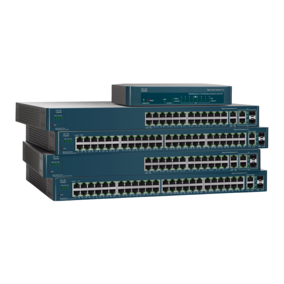
Getting Started Typical Installation Methods In the third scenario, called Heterogeneous Network, you are adding an ESW 500 switch to a network which does not have any Cisco Small Business products. Default Configuration settings on the ESW 500 Series Switches... - Page 15 ESW 540-24/24P ESW 540-24/24P ESW 540-48 ESW 540-48 ESW 540-48 ESW 540-48 Compare the following table with the four examples of switch front panels that are on the next page: ESW 500 Series Switches Administration Guide GE Port Port Description Switch The switch is equipped with auto-sensing, Ethernet (802.3) network ports...
-
Page 16: Esw 500 Series Switches Administration Guide
Getting Started Typical Installation Methods ESW-520-24/24P ESW-520-48/48P ESW-540-24/24P ESW-540-48 ESW 500 Series Switches Administration Guide... -
Page 17: Connecting To The Switch
• • The first three options to connect to the switch will open the ESW 500 Series Switch Configuration Utility, which is a web-based device manager used to provision the switch. The console option uses a terminal emulation program such as HyperTerminal (bundled with Windows) or Putty (freeware). -
Page 18: Esw 500 Series Switches Administration Guide
If your PC is using a static IP address, make note of your current IP address STEP 3 settings, and record them for future use. Place the PC on the same subnet of the switch by configuring the PC with the STEP 4 following parameters: •... -
Page 19: Esw 500 Series Switches Administration Guide
NOTE Click Apply. The STEP 8 ESW 500 Series Switches Administration Guide cisco . Passwords are both case sensitive and alpha-numeric. Click After logging in using the default username and password you must change to a new username and password. Only after the change has been made, can you operate the device through the web browser. -
Page 20: Esw 500 Series Switches Administration Guide
Getting Started Connecting to the Switch Switch Configuration Utility - System Dashboard Click Monitor & Device Properties > System Management > IP Addressing > IPv4 STEP 9 Interface ESW 500 Series Switches Administration Guide IPv4 Interface page opens. - Page 21 STEP 10 and User Defined Default Gateway. These must match the IP addressing subnet in the network in which the ESW 500 switch will be deployed. Click Apply. NOTE Now that you have finished using the PC to connect to the switch and made the...
-
Page 22: Using A Dynamic Ip Address Allocated To The Switch By Dhcp
Access Control (MAC) address of the switch. On the 24 and 48 port models, the MAC address is on the back panel of the switch next to the power adapter. On the 8 port models, the MAC address is on the bottom of the device. The illustration below shows a MAC address of 00211BFE7218. - Page 23 A window opens that prompts you to change your username and password from STEP 4 the default. Choose a new username and password, then click Apply. ESW 500 Series Switches Administration Guide cisco . Passwords are both case sensitive and alpha-numeric.
-
Page 24: Using The Cisco Configuration Assistant (Cca)
(SBCS) or with other Cisco Small Business Pro products such as the SA 500 Series Security Appliance or the AP 541 Access Point. The ESW 500 series switch obtains the management IP address via DHCP after it is connected to the network. - Page 25 STEP 2 expansion port on the UC520 or one of the switch ports on the SR520. Connect the PC with CCA installed to any access switch port on the ESW 500 or STEP 3 alternately, the UC500 or Small Business Pro router.
- Page 26 Getting Started Connecting to the Switch Connect page Once you have connected to the community, the STEP 6 displays the ESW 500 Series Switch. Right-click on the switch and it displays three options: • • • You can now continue with configuring the switch by two different options; use CCA to do all of the configuration, or use the Device Manager to go to the switch Configuration Utility.
- Page 27 Enter a user name and password. The default user name is STEP 8 password is Click Log In. The STEP 9 ESW 500 Series Switches Administration Guide Log In page will launch in a new browser window. cisco . Passwords are both case sensitive and alpha-numeric.
- Page 28 A window opens that prompts you to change your username and password from STEP 10 the default. Choose a new username and password, then click Apply. Switch Configuration Utility - System Dashboard You are now ready to proceed with additional switch configuration. STEP 11 ESW 500 Series Switches Administration Guide...
-
Page 29: Navigating The Cisco Switch Configuration Utility
Navigating The Cisco Switch Configuration Utility The Cisco Switch Configuration Utility is a web-based device manager that is used to provision the switch. You must have IP connectivity between the PC and the switch to configure the switch. The following section describes how to navigate within the interface. -
Page 30: Performing Common Configuration Tasks
Use the menus in the left navigation panel to choose a specific area of configuration. Checking the Software Version To check the version of the software on the switch, click About at the top of the page. Software Version Page Checking the System Information Click on Monitor &... -
Page 31: Viewing What Devices Are Attached To The Switch
Performing Common Configuration Tasks System Information Page From this page you can configure the hostname of the switch, location and contact information for support. Also, you can view important information such as the system uptime, software version, MAC Address and Serial Number (SN). -
Page 32: Configuring The Vlan Settings For The Switch
ESW 500 Series Switches Administration Guide Properties If the ESW 500 series switch is being deployed into a Cisco SBCS network, the installation is plug and play. If the switch is being deployed into a non- Cisco network, you will need to manually change VLAN settings. -
Page 33: Configuring Individual Ports Using Cisco Smartport Roles
Smartport Roles make it easy to provision switch ports by automatically applying the appropriate configuration for attached IP phones, access points, or other devices to optimize network performance. The ESW 500 series switches support the predefined roles listed below: Role... -
Page 34: Smartport Roles
ESW 520-24P ESW 520-48 ESW 520-48P ESW 540-24 ESW 540-24P ESW 540-48 ESW 500 Series Switches Administration Guide Description • Configured for optimal connection to a router or firewall for WAN connectivity • Configured as an uplink port to another switch or router Layer 2 port for fast convergence •... - Page 35 The following steps show one example of using the Smart Ports Setting Wizard to configure access points. It is not necessary to configure your switch in this manner. Click on the System Dashboard, and then on the Smartports Wizard. The...
- Page 36 Smart Ports Settings Wizard - Access Point Click Allow to ensure that VLAN100 shows up in the allowed list, and then click STEP 4 Apply. ESW 500 Series Switches Administration Guide Access Point window opens. To ensure all VLANs in the network...
- Page 37 STEP 5 Smart Ports Settings Wizard - Access Point Setting Status Return to the System Dashboard and click on the Smart Ports Wizard. The icons STEP 6 for ports 4-6 should appear as follows: ESW 500 Series Switches Administration Guide...
-
Page 38: Checking The Device Power Consumption
Getting Started Performing Common Configuration Tasks Smart Ports Setting Checking the Device Power Consumption Check the overview of the power consumption on the switch. Click System Dashboard > PoE Settings. The ESW 500 Series Switches Administration Guide PoE Settings page opens. - Page 39 802.3af Class 2 devices which draw less than 7.5W per device Scenario 2 — Assumes the POE devices connected to the switch are a mix of IEEE 802.3af Class 2 & Class 3 devices devices which on average draw less than 11W per device Scenario 3 —...
-
Page 40: Saving The Configuration
Refer to additional sections in this guide for details on further PoE configuration. Saving the Configuration After any changes, always make sure to save the switch configuration. Click Maintenance > File management > Save Configuration. The page opens. -
Page 41: Upgrading The Firmware On The Switch
Upgrading the Firmware on the Switch The following steps show how to download, install, and make a new firmware release the active image on the switch. ESW 500 Series Switches Administration Guide Save Configuration Page contains the following fields:... - Page 42 If you choose to use TFTP, make sure it is stored in the root directory of the TFTP server running on your PC. Download the software image from the PC to the ESW 500 series switch. Click on STEP 4 Maintenance >...
- Page 43 Choose the new image from the drop-down list under STEP 7 Save the switch configuration. Click Maintenance > File Management > Save STEP 8 Configuration. The Save Co ESW 500 Series Switches Administration Guide Active Image page opens. nfiguration page opens.
- Page 44 Performing Common Configuration Tasks Save Configuration Page Keep the defaults for STEP 9 Reset the switch by clicking on Monitor & Device Properties > System STEP 10 Management > Restart / Reset. ESW 500 Series Switches Administration Guide Source File Name Destination File Name and click Apply.
- Page 45 Getting Started Performing Common Configuration Tasks Restart / Reset Page Click on Reset / Reboot and the switch should reboot with the new image. STEP 11 After the switch has completed rebooting and is up and running, log back in.
-
Page 46: Resetting The Device
Click one of the available Reset commands: STEP 2 • • After the switch has completed rebooting and is up and running, relaunch the STEP 3 Switch Configuration Utility and log back into the switch. ESW 500 Series Switches Administration Guide Reset / Reboot —... -
Page 47: Manual Reset
NOTE Manual Reset The Switch can be reset by inserting a pin or paper clip into the RESET opening. Pressing the manual reset for 0 to 10 seconds reboots the switch. Pressing the manual reset for longer than 10 seconds results in the switch being reset to factory defaults. -
Page 48: Using The Switch Console Port
STEP 1 Connect it to the network if required. STEP 2 Use the console cable supplied with the switch to connect the serial port on the STEP 3 PC to the console port on the switch. ESW 500 Series Switches Administration Guide Function Move the cursor up, down, left, or right. - Page 49 The System Configuration Menu line should be highlighted. Press Enter. The page changes to System Configuration Menu. STEP 7 ESW 500 Series Switches Administration Guide Speed or Bits Per Second — 115200 Data Bits — 8 Stop Bit — 1 Parity —...
- Page 50 Highlight option 1, IPv4 Address Configuration, and press Enter. The IPv4 Address STEP 9 Configuration Menu opens. Highlight option 1, IPv4 Address Settings, and press Enter. The IPv4 Address STEP 10 Settings page opens. ESW 500 Series Switches Administration Guide...
- Page 51 Getting Started Using The Switch Console Port The current IP address setting for the ESW 500 series switch is shown. If the switch is already connected to the network and obtained an IP address via DHCP, this is the IP address which is used to launch the ESW 500 Switch Configuration Utility.
-
Page 52: Chapter 2: Managing Device Information
• Help — Includes online Device Help and More help at Cisco.com To open the Click System Dashboard device opens: ESW 500 Series Switches Administration Guide System Dashboard page is the main window and contains links for System Dashboard Page: (Device Name) . - Page 53 Managing Device Information Understanding the Dashboards System Dashboard (ESW-520-24) Page ESW 500 Series Switches Administration Guide...
- Page 54 Managing Device Information Understanding the Dashboards System Dashboard (ESW-520-24P) Page ESW 500 Series Switches Administration Guide...
- Page 55 Managing Device Information Understanding the Dashboards System Dashboard (ESW-520-48) Page ESW 500 Series Switches Administration Guide...
- Page 56 Managing Device Information Understanding the Dashboards System Dashboard (ESW-520-48P) Page ESW 500 Series Switches Administration Guide...
- Page 57 Managing Device Information Understanding the Dashboards System Dashboard (ESW-540-24) Page ESW 500 Series Switches Administration Guide...
- Page 58 Managing Device Information Understanding the Dashboards System Dashboard (ESW-540-24P) Page ESW 500 Series Switches Administration Guide...
-
Page 59: Ports
Managing Device Information Understanding the Dashboards System Dashboard (ESW-540-48) Page You can edit a specific port on the switch by clicking on that port from the device view. graphical representation: • Green — Indicates the port is currently operating. Ports •... -
Page 60: Common Tasks
Device Help — Opens the online help. • More help at Cisco.com — Provides a link to online Technical Support. Defining System Information information.To open the ESW 500 Series Switches Administration Guide System Information Page contains parameters for configuring general device System Information Page... - Page 61 • System Up Time — Displays the amount of time that has elapsed since the last device reset. The system time is displayed in the following format: Days, Hours, ESW 500 Series Switches Administration Guide System Information Page opens: System Information Page...
-
Page 62: Viewing Device Health
Click Apply. The system information is defined, and the device is updated. STEP 3 Viewing Device Health the device’s power and ventilation sources. ESW 500 Series Switches Administration Guide Enable — Enables Jumbo Frames on the device. Disable — Disables Jumbo Frames on the device. - Page 63 • Fan Status — Displays the fan status. The device has five fans. Each fan is denoted as fan plus the fan number. The possible field values are: ESW 500 Series Switches Administration Guide opens: Health Page contains the following fields: OK —...
-
Page 64: Resetting The Device
Reset / Reboot — Resets the device. Ensure the device configuration has been saved. • Restore Default — The device is restored to the factory default configuration. ESW 500 Series Switches Administration Guide Not Present -- Indicates the fan is not present. Restart / Reset page enables the device to be reset from a remote location. -
Page 65: Managing Cisco Discovery Protocol
The following fields are configurable by the user: • CDP Status — Indicates if CDP is enabled on the device. The possible field values are: ESW 500 Series Switches Administration Guide CDP Page contains the following fields: Enable — Enables CDP on the device. This is the default value. - Page 66 Voice VLAN — The Voice VLAN field displays the current Voice VLAN used by the switch. The default is VLAN #100. This VLAN carries the voice traffic, and is also advertised through the CDP to the other elements in the network. The user can change the Voice VLAN via this screen.
- Page 67 • Device ID — Indicates the name of the neighbor device and either the MAC address or the serial number of the device. ESW 500 Series Switches Administration Guide CDP Status field to enable the Cisco Discovery Protocol on CDP Page...
-
Page 68: Defining The Bonjour Discovery Protocol
Platform — Indicates the product name and number of the neighboring device. • Capabilities — Indicates the device type of the neighbor. This device can be a router, a bridge, a transparent bridge, a source-routing bridge, a switch, a host, an IGMP device, or a repeater. •... - Page 69 Bonjour using the mDNS service. The possible field values are: • Active Bonjour Services — Specifies the Bonjour services supported by the device By default all three serves are published. ESW 500 Series Switches Administration Guide Checked — Enables Bonjour on the device. Bonjour is enabled by default.
-
Page 70: Tcam Utilization
TCAM Allocation To view TCAM Resources: ESW 500 Series Switches Administration Guide HTTP — Specifies the Service Type selected is HTTP. This service is enabled by default, and can be user-disabled but not deleted. The service uses the default port 80. - Page 71 TCAM Utilization – Indicates the percentage of the available TCAM resources which are used. For example, if more ACLs and policy maps are defined, the system uses more TCAM resources. ESW 500 Series Switches Administration Guide opens: TCAM Utilization Page...
-
Page 72: Chapter 3: Managing Smart Ports
• • • • ESW 500 Series Switches Administration Guide Desktop — Allows network administrators to define settings for personal desktop users. IP Phone and Desktop —Allows network administrators to define settings between the switch and the IP Phone. This helps ensure proper network management for voice traffic. -
Page 73: Configuring Smart Ports For Desktops
(e.g., switch, access point etc.). A port will be deactivated or has degraded service by connecting a switch or an access point to IP phone + desktop smartport respectively because of mismatched port role. - Page 74 Open the Switch Configuration Utility. The web application automatically opens STEP 1 to the System Dashboard Page Click Smart Ports Wizard under Ports on the STEP 2 Ports Setting Page ESW 500 Series Switches Administration Guide System Dashboard Page opens: System Dashboard Page . The Smart...
- Page 75 Port — Indicates the port to which Smart Port wizard settings are applied. • VLAN Port Mode — Indicates the VLAN port mode enabled on the port. The possible value is: ESW 500 Series Switches Administration Guide Desktop Assign Profile in the...
- Page 76 Desktop. Select a VLAN in the STEP 5 ESW 500 Series Switches Administration Guide Access — Indicates a port belongs to a single untagged VLAN. This is the default setting for ports that are connected to desktops.
-
Page 77: Configuring Smart Ports For Ip Phones And Desktops
STEP 6 Configuring Smart Ports for IP Phones and Desktops to define settings between the switch and the IP Phone. This helps ensure proper network management for voice traffic. The Smart Port IP Phone and Desktop wizard allows network mangers to connect a phone and a PC. - Page 78 IP voice traffic from IP phones on specific VLANs. • Port Security Mode — Defines the locked port type. The possible field value ESW 500 Series Switches Administration Guide Smart Ports IP Phones and Desktop Settings Page Trunk — Indicates the port belongs to VLANs in which all VLANs are tagged, except for one VLAN that is untagged.
- Page 79 Click Apply. The IP Phone + Desktop port settings are saved, and the device is STEP 6 updated. Click OK. The Smart ports Setting page opens. STEP 7 ESW 500 Series Switches Administration Guide Discard — Discards packets from any unlearned source. This is the default value. Data VLAN drop-down list.
-
Page 80: Configuring Smart Ports For Access Points
Select a port or range of ports. STEP 3 Select STEP 4 Click Next. The Smart Ports Access Point Settings Page opens:. STEP 5 ESW 500 Series Switches Administration Guide Smart Ports for Access Points Page System Dashboard Page Page opens: Access Points Assign Profile... - Page 81 Macro Description — Indicates the type of device connected to the port. For access points, this field is always Select a VLAN in the STEP 6 ESW 500 Series Switches Administration Guide Smart Ports for Access Points Settings Page Trunk — Indicates the port belongs to VLANs in which all VLANs are tagged, except for one VLAN that is untagged.
-
Page 82: Configuring Smart Ports For Switches
STEP 2 Ports Setting Page Smart Ports Setting Page Select a port or range of ports. STEP 3 ESW 500 Series Switches Administration Guide Smart Ports Switch Settings Page System Dashboard Page opens: allows network administrators to manage System Dashboard Page Smart . - Page 83 • QoS Policy — Indicates that the default QoS policy settings are applied to the port. The name of the default QoS policy is switch-map. ESW 500 Series Switches Administration Guide Switch Assign Profile in the...
-
Page 84: Configuring Smart Ports For Routers
STEP 1 to the Click Smart Ports Wizard under Ports on the STEP 2 Ports Setting ESW 500 Series Switches Administration Guide Switch. Trunk Native VLAN ID Smart Port Router Page allows network administrators to manage network System Dashboard Page Page opens: drop-down list. - Page 85 Smart Ports Setting Page Select a port or range of ports. STEP 3 Select STEP 4 Click Next. The STEP 5 ESW 500 Series Switches Administration Guide Router Assign Profile in the drop-down list. Smart Port Router Settings Page opens:...
- Page 86 Macro Description — Indicates the type of device connected to the port. For routers, this field is always Select a VLAN in the STEP 6 ESW 500 Series Switches Administration Guide Edit Smart Port Router Page contains the following fields: Trunk —...
-
Page 87: Configuring Smart Ports For Guests
Click OK. The Smart ports Setting page opens. STEP 9 Configuring Smart ports for Guests settings between the switch and a guest in the company. It is recommended that this connection be restricted to specific applications. To configure Smart ports for a guest: Open the Small Business Pro web application. - Page 88 STEP 6 Click Apply. The guest port settings are saved, and the device is updated. STEP 7 Click OK. The STEP 8 ESW 500 Series Switches Administration Guide Smartports Guest Settings Page Access — Indicates the value is Access. Guest.
-
Page 89: Configuring Smart Ports For Servers
STEP 3 Select STEP 4 Smart ports Setting Page Click Next. The STEP 5 ESW 500 Series Switches Administration Guide Smart ports Setting Page allows network administrators to define settings Server in the Assign Role dropdown Smart ports Server Settings Page Ports are enabled for the Smart Port box. - Page 90 Spanning Tree Port Fast — Indicates Fast Link is enabled on the port. If Fast Link mode is enabled for a port, the Port State is automatically placed in the ESW 500 Series Switches Administration Guide Smart ports Server Settings Page Access —...
-
Page 91: Configuring Smart Ports For Printers
STEP 2 wizards by default. Select a port or range of ports. STEP 3 Select STEP 4 ESW 500 Series Switches Administration Guide Server. VLAN ID dropdown box. Smart ports Setting Smart ports Setting Page allows network administrators to define settings Ports are enabled for the Smart Port wizards by default. - Page 92 Ports — Indicates the port to which Smart ports Wizard settings are applied. • VLAN Port Mode — Indicates the VLAN port mode enabled on the port. The value is: ESW 500 Series Switches Administration Guide Smartports Printer Settings Page Smartports Printer Settings Page Access —...
- Page 93 Click Apply. The Server port settings are saved, and the device is updated. STEP 7 Click OK. The STEP 8 ESW 500 Series Switches Administration Guide Discard — Discards packets from any unlearned source. This is the default value. Printer.
-
Page 94: Configuring Smart Ports For Vs Camera
STEP 4 Smart ports Setting Page Click Next. The STEP 5 ESW 500 Series Switches Administration Guide Smart ports Setting Page allows network administrators to define settings Ports are enabled for the Smart Port wizards by default. However, the VS Camera... - Page 95 • Broadcast Storm Control — Indicates the percentage of Broadcast Storm Control enabled on the port. The value is 10% of the port speed. ESW 500 Series Switches Administration Guide Smart ports Server Settings Page Access — Indicates the value is Access.
-
Page 96: Configuring Smart Ports For Other
SPAN to send a copy of the traffic to another port on the switch or on another switch that has been connected to a network analyzer or other monitoring or security device. The following are the steps to set up port mirroring: Select the destination port. - Page 97 Select a port or range of ports. STEP 3 Select Other in the STEP 4 Click Next, the Other page opens. STEP 5 ESW 500 Series Switches Administration Guide System Dashboard Page Page opens: Assign Profile drop-down list. System Dashboard Page .
- Page 98 STEP 6 Click Apply. The port settings are saved, and the device is updated. STEP 7 ESW 500 Series Switches Administration Guide Edit Smart Port Other Page contains the following fields: Ports — Indicates the port to which Smart Port wizard settings are applied.
-
Page 99: Chapter 4: Configuring System Time
SNTP clock, and the external SNTP clock fails, the system time reverts to the local hardware clock. Daylight Savings Time can be enabled on the device. To define system time: ESW 500 Series Switches Administration Guide System Time Page contains fields for defining system time parameters for... - Page 100 21:15:03. • Time Zone Offset — Indicates the difference between (GMT) and local time. For example, the Time Zone Offset for Paris is GMT +1, ESW 500 Series Switches Administration Guide System Time Page opens: System Time Page contains the following fields: Use Local Settings —...
- Page 101 Day:Month:Year format in one field and time in another. For example, DST ends on the 23rd March 2008 12:00 am, the two fields will be 23/Mar/08 and 12:00. The possible field values are: ESW 500 Series Switches Administration Guide area, and for a recurring setting, complete the USA —...
- Page 102 Define the relevant fields. STEP 2 Click Apply. The Time Settings are defined, and the device is updated. STEP 3 ESW 500 Series Switches Administration Guide Month — The month of the year in which DST ends. The possible field range is Jan-Dec.
-
Page 103: Defining Sntp Settings
Poll Interval — Defines the interval (in seconds) at which the SNTP server is polled for system time information. By default, the poll interval is 1024 seconds. ESW 500 Series Switches Administration Guide SNTP Settings Page contains information for enabling SNTP servers, as well... - Page 104 • Delay — Indicates the amount of time it takes to reach the SNTP server. Click the Add button. The STEP 2 ESW 500 Series Switches Administration Guide Primary — The primary server provides SNTP information. Secondary — The backup server provides SNTP information.
-
Page 105: Defining Sntp Authentication
Click Apply. The SNTP Server is added, and the device is updated. STEP 4 Defining SNTP Authentication of the SNTP server. ESW 500 Series Switches Administration Guide Add SNTP Server Page contains the following fields: SNTP Authentication Page provides parameters for performing authentication... - Page 106 Trusted Key — Indicates the encryption key used (Unicast/Anycast) or elected (Broadcast) to authenticate the SNTP server. Click the Add button. The STEP 2 ESW 500 Series Switches Administration Guide SNTP Authentication Page SNTP Authentication Page contains the following fields: Checked —...
- Page 107 (Broadcast) to authenticate the SNTP server. Define the relevant fields. STEP 3 Click Apply. The SNTP Authentication is defined, and the device is updated. STEP 4 ESW 500 Series Switches Administration Guide Add SNTP Authentication Page contains the following fields:...
-
Page 108: Chapter 5: Configuring Device Security
By default, a single user name is defined, cisco, with a password of When a new Local User is added, the default user name, NOTE To define Passwords: ESW 500 Series Switches Administration Guide cisco cisco will be overwritten. - Page 109 • User Name — Displays the user name. Click the Add button. The STEP 2 Add Local User Page ESW 500 Series Switches Administration Guide opens: User Authentication Page contains the following fields: Add Local User Page Add Local User Page...
-
Page 110: Modifying The Local User Settings
Confirm Password — Confirms the new password. The password entered into this field must be exactly the same as the password entered in the Password field. ESW 500 Series Switches Administration Guide opens: Edit Local User Page Edit Local User Page... -
Page 111: Defining Authentication
If the first authentication method is not available, the next selected method is used. For example, if the selected authentication methods are RADIUS and Local, and the RADIUS server is not available, then the user is authenticated locally. ESW 500 Series Switches Administration Guide... - Page 112 Note that if the RADIUS server is available, but authentication fails, then the user is denied access. The possible field values are: Click the Add button. The STEP 2 ESW 500 Series Switches Administration Guide Profiles Page contains the following fields: Local —...
- Page 113 Define the relevant fields. STEP 3 Click Apply. The authentication profile is defined, the device is updated. STEP 4 ESW 500 Series Switches Administration Guide Add Authentication Profile Page Local — Authenticates the user at the device level. The device checks the user name and password for authentication.
-
Page 114: Modifying An Authentication Profile
Define the relevant fields. STEP 3 Click Apply. The authentication profile is defined, the device is updated. STEP 4 ESW 500 Series Switches Administration Guide Edit Authentication Profile Page Edit Authentication Profile Page Local — Authenticates the user at the device level. The device checks the user name and password for authentication. -
Page 115: Mapping Authentication Profiles
Console — Indicates that Authentication profiles are used to authenticate console users. • Telnet — Indicates that Authentication profiles are used to authenticate Telnet users. ESW 500 Series Switches Administration Guide Mapping Profiles Page contains parameters for mapping authentication Mapping Profiles Page contains the following fields:... - Page 116 Define the relevant fields. STEP 2 Click Apply. Mapping Profiles is defined, and the device is updated. STEP 3 ESW 500 Series Switches Administration Guide — Lists available authentication methods. Local — Authenticates the user at the device level. The device checks the user name and password for authentication.
-
Page 117: Defining Tacacs
TACACS+ servers. If default values are not defined, the system defaults are applied to the new TACACS+ new servers. The Page servers. To define TACACS+: ESW 500 Series Switches Administration Guide contains fields for assigning the Default Parameters for the TACACS+ TACACS+... - Page 118 TACACS+ session between the device and the TACACS+ server. • Authentication Port — Displays the port number through which the TACACS+ session occurs. The default is port 49. ESW 500 Series Switches Administration Guide TACACS+ Page contains the following fields: TACACS+ Page...
- Page 119 Source IP Address — Defines the device source address used for the TACACS+ session between the device and the TACACS+ server. The possible values are: ESW 500 Series Switches Administration Guide Connected — Indicates there is currently a connection between the device and the TACACS+ server.
-
Page 120: Modifying Tacacs+ Settings
STEP 1 Click the Edit Button. The STEP 2 ESW 500 Series Switches Administration Guide Use Default — Uses the default value for the parameter. If Use Default check box is selected, the global value of 0.0.0.0. is used and interpreted as a request to use the IP address of the outgoing IP interface. - Page 121 1-30 seconds. • Status — Displays the connection status between the device and the TACACS+ server. The possible field values are: ESW 500 Series Switches Administration Guide Edit TACACS+ Server Page contains the following fields: Connected — Indicates there is currently a connection between the device and the TACACS+ server.
-
Page 122: Defining Radius
RADIUS servers. To define RADIUS: Click Security > Authentication > RADIUS. The STEP 1 RADIUS Page ESW 500 Series Switches Administration Guide RADIUS Page contains the following fields: (RADIUS) servers provide additional RADIUS Page... - Page 123 RADIUS server before retrying the query, or switching to the next server. The possible field values are 1 - 30. Three is the default value. ESW 500 Series Switches Administration Guide 802. 1 x — 802. 1 x authentication is used to initiate accounting.
- Page 124 Click the Add button. The STEP 2 Add RADIUS Server Page • Host IP Address — Displays the ESW 500 Series Switches Administration Guide Login — Indicates that the RADIUS server is used for authenticating user name and passwords. 802. 1 X —...
- Page 125 • Use Default — Uses the default value for the parameter. Define the relevant fields. STEP 3 ESW 500 Series Switches Administration Guide Login — Indicates that the RADIUS server is used for authenticating user name and passwords. 802. 1 X —...
-
Page 126: Modifying Radius Server Settings
Authentication Port — Displays the authentication port. The authentication port is used to verify the RADIUS server authentication. The authentication port default is 1812. ESW 500 Series Switches Administration Guide Edit RADIUS Server Page Edit RADIUS Server Page contains the following fields:... -
Page 127: Defining Access Methods
STEP 4 Defining Access Methods The access method section contains the following pages: • Defining Access Profiles ESW 500 Series Switches Administration Guide Login — Indicates that the RADIUS server is used for authenticating user name and passwords. 802. 1 X —... -
Page 128: Defining Access Profiles
SNMP Management access to different management methods may differ between user groups. For example, User Group 1 can access the switch module only via an HTTPS session, while User Group 2 can access the switch module via both HTTPS and Telnet sessions. The Access Profile Page contains the currently configured access profiles and their activity status. - Page 129 32 characters. • Current Active Access Profile — Defines the access profile currently active. Click the Add button. The STEP 2 ESW 500 Series Switches Administration Guide Access Profiles Page contains the following fields: Add Access Profile Page Access Profiles Page...
- Page 130 Management Method — Defines the management method for which the rule is defined. Users with this access profile can access the device using the management method selected. The possible field values are: ESW 500 Series Switches Administration Guide — Assigns all management methods to the rule. Telnet —...
-
Page 131: Defining Profile Rules
Defining Profile Rules Access profiles can contain up to 128 rules that determine which users can manage the switch module, and by which methods. Users can also be blocked from accessing the device. Rules are composed of filters including: ESW 500 Series Switches Administration Guide HTTP —... - Page 132 The rule number is essential to matching packets to rules, as packets are matched on a first-fit basis. ESW 500 Series Switches Administration Guide Profile Rules Page contains the following fields:...
- Page 133 • Action — Defines the action attached to the rule. The possible field values are: Click the Add button. The STEP 2 ESW 500 Series Switches Administration Guide Port — Attaches the rule to the selected port. EtherChannel — Attaches the rule to the selected EtherChannel.
- Page 134 Management Method — Defines the management method for which the rule is defined. Users with this access profile can access the device using the management method selected. The possible field values are: ESW 500 Series Switches Administration Guide Add Profile Rule Page contains the following fields: —...
-
Page 135: Modifying Profile Rules
Click Security > Access Method > Profile Rules. The STEP 1 Click the Edit button. The STEP 2 ESW 500 Series Switches Administration Guide HTTP — Assigns HTTP access to the rule. If selected, users accessing the device using HTTP meeting access profile criteria are permitted or denied access to the device. - Page 136 Management Method — Defines the management method for which the rule is defined. Users with this access profile can access the device using the management method selected. The possible field values are: ESW 500 Series Switches Administration Guide Edit Profile Rule Page contains the following fields: —...
-
Page 137: Defining Traffic Control
STEP 4 Defining Traffic Control The Traffic Control section contains the following pages: ESW 500 Series Switches Administration Guide HTTP — Assigns HTTP access to the rule. If selected, users accessing the device using HTTP meeting access profile criteria are permitted or denied access to the device. -
Page 138: Defining Storm Control
Storm Control is enabled per port on GE devices, and per system on FE devices (not NOTE applicable to ESW 520-8P devices). To define storm control: ESW 500 Series Switches Administration Guide Storm Control Page provides fields for configuring Broadcast Storm Control. - Page 139 • Enable Broadcast Control — Indicates if Broadcast packet types are forwarded on the specific interface. The possible field values are: ESW 500 Series Switches Administration Guide Storm Control Page contains the following fields: — On FE devices, sets the maximum rate (packets per Enable —...
-
Page 140: Modifying Storm Control
STEP 1 Click the Edit Button. The STEP 2 Edit Storm Control Page ESW 500 Series Switches Administration Guide Disable — Disables Broadcast packet types to be forwarded. For FE ports, the rate is 70 - 100,000 Kbps. For GE ports, the rate is 3,500 - 100,000 Kbps. -
Page 141: Defining Port Security
MAC addresses. These addresses are either manually defined on the port, or learned on that port up to the point when it is ESW 500 Series Switches Administration Guide Checked — Enables Broadcast packet types to be forwarded. - Page 142 The MAC address list can be restored after the device has been reset. Disabled ports are activated from the Port Security Page. To configure port lock, 802. 1 x multiple host mode must be enabled. NOTE To define port security: ESW 500 Series Switches Administration Guide...
- Page 143 Learning Mode, the Lock Interface must be set to Unlocked. Once the mode is changed, the Lock Interface can be reinstated.The possible field values are: ESW 500 Series Switches Administration Guide Port Security Page contains the following fields: Unlocked —...
- Page 144 STEP 2 Click Apply. Port security is defined, and the device is updated. STEP 3 ESW 500 Series Switches Administration Guide Classic Lock — Locks the port using the classic lock mechanism. The port is immediately locked, regardless of the number of addresses that have already been learned.
-
Page 145: Modifying Port Security
Learning Mode, the Lock Interface must be set to Unlocked. Once the mode is changed, the Lock Interface can be reinstated. The possible field values are: ESW 500 Series Switches Administration Guide Edit Port Security Page Edit Port Security Page... -
Page 146: Defining 802.1X
Ports are authenticated via the RADIUS server using the Extensible Authentication Protocol (EAP). Port Authentication includes: ESW 500 Series Switches Administration Guide maximum addresses allowed on the port. Both relearning and aging MAC addresses are enabled. Previously learned MAC addresses are not deleted but are converted to a static MAC address. -
Page 147: Defining 802.1X Properties
Defining Port Authentication • Defining Authentication • Defining Authenticated Host Defining 802.1X Properties The 802. 1 X Properties Page provides parameters for enabling port authentication, and selecting the authentication method. To define port based authentication: ESW 500 Series Switches Administration Guide... - Page 148 • Guest VLAN — Specifies whether the Guest VLAN is enabled on the device. The possible field values are: ESW 500 Series Switches Administration Guide 802. 1 X Properties Page contains the following fields: Enable — Enables port-based authentication on the device.
-
Page 149: Defining Port Authentication
Click Apply. The 802. 1 X properties are defined, and the device is updated. STEP 3 Defining Port Authentication ports. ESW 500 Series Switches Administration Guide Checked — Enables using a Guest VLAN for unauthorized ports. If a Guest VLAN is enabled, the unauthorized port automatically joins the... - Page 150 Guest VLAN — Displays the Guest VLAN. • Authentication Method — Displays the authentication method in use. The possible field values are: ESW 500 Series Switches Administration Guide opens: 802. 1 X Port Authentication Page 802. 1 x Only — Enables only 802. 1 x authentication on the device.
- Page 151 Authenticator State — Specifies the port authorization state. The possible field values are as follows: • Quiet Period — Specifies the number of seconds that the switch remains in the quiet state following a failed authentication exchange (Range: 0-65535). •...
-
Page 152: Modifying 8021X Security
Current Port Control — Displays the current port authorization state. • Admin Port Control — Defines the admin port authorization state. The possible field values are: ESW 500 Series Switches Administration Guide Port Authentication Settings Page Port Authentication Settings Page 802. 1 X Properties Page... - Page 153 • Reauthenticate Now — Specifies that authentication is applied on the device when the Apply button is pressed. ESW 500 Series Switches Administration Guide auto — Enables port-based authentication on the device. The interface moves between an authorized or unauthorized state based on the authentication exchange between the device and the client.
- Page 154 Authenticator State — Specifies the port authorization state. The possible field values are as follows: • Quiet Period — Specifies the number of seconds that the switch remains in the quiet state following a failed authentication exchange (Range: 0-65535). •...
-
Page 155: Defining Authentication
• Host Authentication— Defines the Host Authentication mode. The possible field values are: ESW 500 Series Switches Administration Guide 802. 1 X Authentication Page allows network managers to configure advanced 802. 1 X Authentication Page contains the following fields: Single —... - Page 156 Number of Violations — Indicates the number of packets that arrived on the interface in single-host mode, from a host whose MAC address is not the supplicant MAC address. ESW 500 Series Switches Administration Guide Forward — Forwards the packet.
-
Page 157: Modifying Authentication Settings
Action on Violation — Defines the action to be applied to packets arriving in single-host mode, from a host whose MAC address is not the supplicant MAC address. The possible field values are: ESW 500 Series Switches Administration Guide Edit Authentication Page Edit Authentication Page... -
Page 158: Authenticated Hosts
STEP 3 Click Apply. The authentication settings are defined, and the device is updated. STEP 4 Authenticated Hosts ESW 500 Series Switches Administration Guide Discard — Discards the packets. This is the default value. Shut Down — Discards the packets and shuts down the port. The ports remains shut down until reactivated, or until the device is reset. - Page 159 • Authentication Method — Displays the method by which the last session was authenticated. The possible field values are: ESW 500 Series Switches Administration Guide Authenticated Hosts Page contains the following fields: Remote — Indicates the 802. 1 x authentication is not used on this port (port is forced-authorized).
-
Page 160: Defining Access Control
Defining Access Control Access Control Lists (ACL) allow network managers to define classification actions and rules for specific ingress ports. Your switch supports up to 256 ACLs. Packets entering an ingress port, with an active ACL, are either admitted or denied entry. - Page 161 Inner VLAN — Matches the ACE to the inner VLAN ID of a double tagged packet. • 802. 1 p — Displays the packet tag value. ESW 500 Series Switches Administration Guide MAC Based ACL Page contains the following fields:...
- Page 162 The possible field values are 1- 2147483647. • Source MAC Address: ESW 500 Series Switches Administration Guide Permit — Forwards packets which meet the ACL criteria. Deny — Drops packets which meet the ACL criteria.
- Page 163 Ethertype — Displays the Ethernet type of the packet. • Action — Indicates the ACL forwarding action. The possible field values are: ESW 500 Series Switches Administration Guide MAC Addres s — Matches the source MAC address from which packets are addressed to the ACE.
-
Page 164: Adding Rule To Mac Based Acl
New Rule Priority — Indicates the ACE priority, which determines which ACE is matched to a packet on a first-match basis. The possible field values are 1- 2147483647. • Source MAC Address ESW 500 Series Switches Administration Guide Page opens. ACL Name Add Rule Page Add MAC Based Rule Page... - Page 165 Ethertype — Displays the Ethernet type of the packet. • Action — Indicates the ACL forwarding action. The possible field values are: ESW 500 Series Switches Administration Guide MAC Addres s — Matches the source MAC address from which packets are addressed to the ACE.
-
Page 166: Modifying Mac Based Acl
Rule Priority — Indicates the rule priority, which determines which rule is matched to a packet on a first-match basis. • Source MAC Address: ESW 500 Series Switches Administration Guide opens. Rule Settings Page Rule Settings Page contains the following fields: MAC Addres s —... - Page 167 Action — Indicates the ACL forwarding action. The possible field values are: Define the relevant fields, STEP 3 ESW 500 Series Switches Administration Guide Wildcard Mask — Indicates the source MAC Address wild card mask. Wildcards are used to mask all or part of a source MAC Address. Wild card masks specify which octets are used and which octets are ignored.
-
Page 168: Defining Ip Based Acl
• Rule Priority — Indicates the rule priority, which determines which rule is matched to a packet on a first-match basis. ESW 500 Series Switches Administration Guide IP Based ACL Page page contains information for defining IP Based ACLs, opens:... - Page 169 Defining Access Control • Protocol — Creates an ACE based on a specific protocol. The possible field values are: ESW 500 Series Switches Administration Guide ICMP Internet Control Message Protoco — gateway or destination host to communicate with the source host. For example, to report a processing error.
- Page 170 ICMP packets that are filtered by ICMP message type can also be filtered by the ICMP message code. • IGMP Type — Filters packets by IGMP message or message types. • Source ESW 500 Series Switches Administration Guide Authentication Header — and data integrity. EIGRP Enhanced Interior Gateway Routing Protocol —...
- Page 171 Delete Rule button. Click the Add ACL button. The STEP 2 ESW 500 Series Switches Administration Guide IP Address — Displays the source port IP address to which packets are addressed to the ACE. Wildcard Mask — Displays the source IP address wildcard mask.
- Page 172 Filtering packets by TCP EtherChannels increases packet control, which increases network security. Once the box is checked, there are other parameters that can be selected from the dropdown menu: ESW 500 Series Switches Administration Guide Add IP Based ACL Page contains the following fields: Urg —...
- Page 173 Match IP Precedence — Matches the packet IP Precedence value to the ACE. Either the DSCP value or the IP Precedence value is used to match packets to ACLs. The possible field range is 0-7. ESW 500 Series Switches Administration Guide Psh — Push Rst — Reset Syn —...
-
Page 174: Modifying Ip Based Acl
Click Security > Access Control Lists (ACL) > IP Based ACL. The STEP 1 Page Click the Edit button. The STEP 2 ESW 500 Series Switches Administration Guide Checked — Matches packets to traffic classes. Unchecked — Does not match packets to traffic classes. - Page 175 Filtering packets by TCP EtherChannels increases packet control, which increases network security. • ICMP — Indicates if ICMP packets are permitted on the network. The possible field values are as follows: ESW 500 Series Switches Administration Guide ACL Page above.
- Page 176 The options are as follows: ESW 500 Series Switches Administration Guide IP Address — Matches the source port IP address from which packets are addressed to the ACE.
-
Page 177: Adding An Ip Based Rule
• Protocol — Creates an ACE based on a specific protocol. For a list of available protocols, see the Protocol field description in the ESW 500 Series Switches Administration Guide opens: Add IP Based Rule Page Add IP Based Rule Page... - Page 178 The options are as follows: ESW 500 Series Switches Administration Guide Match DSCP — Matches the packet to the DSCP tag value. Match IP Precedence — Matches the packet IP Precedence value to the ACE.
-
Page 179: Defining Acl Binding
Click Security > Access Control Lists (ACL) > ACL Binding. The STEP 1 opens: ACL Binding Page • Copy From Entry Number — Copies the ACL binding configuration from the specified table entry. ESW 500 Series Switches Administration Guide ACL Binding Page contains the following fields: ACL Binding Page... -
Page 180: Modifying Acl Binding
Select IP Based ACL — Indicates the IP based ACL which is bound to the interface. Define the relevant fields. STEP 3 ESW 500 Series Switches Administration Guide Edit ACL Binding Page Edit ACL Binding Page contains the following fields:... -
Page 181: Defining Dos Prevention
Defining Martian Addresses DoS Global Settings DoS attack prevention parameters on the device. To open the Page ESW 500 Series Switches Administration Guide (DOS) increases network security by preventing packets with Global Settings Page allows network managers to enable and define global... - Page 182 16660 • Invasor Trojan — Discards TCP packets with destination TCP port equal to 2140 and source TCP port equal to 1024. ESW 500 Series Switches Administration Guide Global Settings Page contains the following fields: Enable — Enables DoS security.
-
Page 183: Defining Martian Addresses
This formerly known as Class D Address Space. • 240.0.0.0/4 (Except 255.255.255.255/32 as a Destination Address) — Reserved address range, and is formerly known as Class E Address Space. To define Martian Addresses: ESW 500 Series Switches Administration Guide... - Page 184 Delete — To remove a Martian address, click the entry’s checkbox and click the delete button. Click the Add button. The STEP 2 ESW 500 Series Switches Administration Guide opens: Martian Addresses Page contains the following fields: 0.0.0.0/8 (except 0.0.0.0/32), 127.0.0.0/8 192.0.2.0/24 , 224.0.0.0/4...
-
Page 185: Defining Dhcp Snooping
Trusted interfaces receive packets only from within the network or the network firewall. ESW 500 Series Switches Administration Guide One of the addresses in the Martian IP address list. New IP Address — Enter an IP Address that is not on the list. -
Page 186: Defining Dhcp Snooping Properties
• Defining IP Source Guard Defining DHCP Snooping Properties Snooping on the device. To define the DHCP Snooping general properties: ESW 500 Series Switches Administration Guide DHCP Snooping Table contains the untrusted interfaces MAC address, IP DHCP Snooping Properties Page... - Page 187 Option 82 information, while DHCP Snooping is enabled. • Verify MAC Address — Indicates if the MAC address is verified. The possible field values are: ESW 500 Series Switches Administration Guide opens: DHCP Snooping Properties Page Checked — Enables DHCP Snooping on the device.
-
Page 188: Defining Dhcp Snooping On Vlans
DHCP snooping on VLANs. To enable DHCP Snooping on a VLAN, ensure DHCP Snooping is enabled on the device. To define DHCP Snooping on VLANs: ESW 500 Series Switches Administration Guide Checked — Verifies (on an untrusted port) that the source MAC address of the Layer 2 header matches the client hardware address as appears in the DHCP Header (part of the payload). -
Page 189: Defining Trusted Interfaces
Enabled VLANs list. Defining Trusted Interfaces interfaces. The device transfers all DHCP requests to trusted interfaces. To define trusted interfaces: ESW 500 Series Switches Administration Guide opens: DHCP Snooping VLAN Settings Page Trusted Interfaces Page allows network managers to define Trusted... - Page 190 From the global Interface field, select either Ports or EtherChannels radio button. STEP 2 In the table, select an interface and click Edit. The STEP 3 opens. ESW 500 Series Switches Administration Guide opens: Trusted Interfaces Page contains the following fields: Trusted Interfaces...
-
Page 191: Binding Addresses To The Dhcp Snooping Database
Binding Addresses to the DHCP Snooping Database addresses to the DHCP Snooping Database. To bind addresses to the DHCP Snooping database: ESW 500 Series Switches Administration Guide Edit Trusted Interface Page contains the following field: Enable — Interface is in trusted mode. -
Page 192: Query By
• Interface — Contains a list of interface by which the DHCP Database can be queried. The possible field values are: ESW 500 Series Switches Administration Guide Ports — Queries the VLAN database by a port number. Binding Database Page... -
Page 193: Query Results
The possible values are 10 – 4294967295 seconds. In the the DHCP Snooping entry never expires. Click Add. The STEP 4 ESW 500 Series Switches Administration Guide EtherChannel — Queries the VLAN database by EtherChannel number. Static — Indicates the IP address is static. - Page 194 STEP 7 To remove dynamic addresses from the Query Results table, click Clear Dynamic. STEP 8 ESW 500 Series Switches Administration Guide Static — Indicates the IP address is static. — Indicates the IP address is defined as a dynamic address in...
-
Page 195: Defining Ip Source Guard
IP Source Guard on the device. IP Source Guard must be enabled for the device before it can be enabled on individual ports or EtherChannels. To enable IP Source Guard: ESW 500 Series Switches Administration Guide before it can be enabled on the device interfaces. IP Source Guard Properties Page... - Page 196 STEP 2 Click Apply. The IP Source Guard configuration is modified, and the device is STEP 3 updated. ESW 500 Series Switches Administration Guide opens: IP Source Guard Properties Page Enable — Indicates that IP Source Guard is enabled for the device.
-
Page 197: Defining Ip Source Guard Interface Settings
If a port’s status changes from untrusted to trusted, the static IP address filtering entries remain but become inactive. ESW 500 Series Switches Administration Guide IP Source Guard Interface Settings Page IP Source Guard must be enabled globally in the before it can be enabled on the device interfaces. - Page 198 Status — Indicates if IP Source Guard is enabled or disabled. Click Edit. The STEP 2 ESW 500 Series Switches Administration Guide IP Source Guard Interface Settings Page Enable — Indicates that IP Source Guard is enabled on the interface.
-
Page 199: Querying The Ip Source Binding Database
Querying the IP Source Binding Database and view information about inactive addresses recorded in the DHCP Database. To query the IP Source Guard Database: ESW 500 Series Switches Administration Guide IP Source Guard Binding Database Page enables network managers to query... -
Page 200: Tcam Resources
If TCAM resources are not available, IP source guard addresses may become inactive. The switch can try to activate inactive addresses in various time intervals: ESW 500 Series Switches Administration Guide IP Source Guard Binding Database Page Retry Frequency —... -
Page 201: Query By
Type — Displays the IP address type. The possible field values are: • Reason — Displays the reason an IP source address is inactive. The possible field options are: ESW 500 Series Switches Administration Guide Port — Queries the database by a specific port number. EtherChannel —... -
Page 202: Defining Dynamic Arp Inspection
Untrusted — Indicates that the packet arrived from an interface that does not have a recognized IP and MAC addresses. The packet is checked for: ESW 500 Series Switches Administration Guide VLAN — Indicates that DHCP Snooping is not enabled on the VLAN. -
Page 203: Defining Arp Inspection Properties
Assigning ARP Inspection VLAN Settings Defining ARP Inspection Properties global Dynamic ARP Inspection parameters, as well as defining ARP Inspection Log parameters. To define ARP Inspection properties: ESW 500 Series Switches Administration Guide ARP Inspection Properties Page provides parameters for enabling and setting... - Page 204 Enable ARP Inspection — Enables ARP Inspection on the device. The possible field values are: • ARP Inspection Validate — Enables ARP Inspection Validation on the device. The possible field values are: ESW 500 Series Switches Administration Guide ARP Inspection Properties Page Checked — Enables ARP Inspection on the device. Unchecked —...
-
Page 205: Defining Arp Inspection Trusted Interfaces
DHCP snooping. ARP Inspection is enabled only on untrusted interfaces. To define trusted interfaces: ESW 500 Series Switches Administration Guide Retry Frequency — Frequency at which the log is updated. The possible range is 0-86400 seconds. 0 seconds specifies immediate transmissions of Syslog messages. - Page 206 Interface — Displays the interface on which edits can be made. • Trust — Enables or disables ARP Inspection Trust mode on the interface. The possible field values are: ESW 500 Series Switches Administration Guide opens: ARP Inspection Trusted Interfaces Page Enable —...
-
Page 207: Defining Arp Inspection List
Lists. ARP Binding Lists contain the List Name, IP address and MAC address which are validated against ARP requests and replies. To add an ARP Inspection List entry: ESW 500 Series Switches Administration Guide Edit Interface Settings Page ARP Inspection List Page... -
Page 208: Static Arp Inspection Table
The Binding list cannot be added until an ARP list is added. NOTE Click Add under ARP Inspection List Name. The STEP 2 ESW 500 Series Switches Administration Guide opens: ARP Inspection List Page contains the following fields: ARP Inspection List... -
Page 209: Adding A Binding List Entry
Click Add under Static ARP Table. The STEP 2 Add ARP Binding Page Define the fields. STEP 3 Click Apply. The add ARP Binding entry is added, and the device is updated. STEP 4 ESW 500 Series Switches Administration Guide Add ARP Binding Page opens:... -
Page 210: Assigning Arp Inspection Vlan Settings
If you add a list in the steps above, then the list will be populated with all the entries. To define ARP Inspection on VLANs: ESW 500 Series Switches Administration Guide ARP Inspection VLAN Settings Page contains fields for enabling ARP... -
Page 211: Enabled Vlan Table
Enter the name of a VLAN ID from the VLAN ID list and click Add. This VLAN ID then STEP 2 appears in the list. The ESW 500 Series Switches Administration Guide opens: ARP Inspection VLAN Settings Page Add ARP VLAN Settings Page... - Page 212 Define the fields. STEP 3 Click Apply. The new ARP VLAN configuration is defined, and the device is STEP 4 updated. ESW 500 Series Switches Administration Guide Add ARP VLAN Settings Page ARP Inspection List Page. contains the following fields:...
-
Page 213: Chapter 6: Configuring Ports
Copy From Entry Number — Copies the port configuration from the specified table entry. • To Entry Number(s) — Assigns the copied port configuration to the specified table entry. • Interface — Displays the port number. ESW 500 Series Switches Administration Guide opens: Port Settings... - Page 214 STEP 2 numbers in the Copy From Entry Number and To Entry Number(s) fields. Click Apply. The Port Settings are defined, and the device is updated. STEP 3 ESW 500 Series Switches Administration Guide 100M — Copper 1000M — Copper (copper cable).
-
Page 215: Modifying Port Settings
Description — Use this field to optionally define a name for the port. • Port Type — Displays the port type. The possible field values are: ESW 500 Series Switches Administration Guide opens: Edit Port Page contains the following fields:... - Page 216 Negotiation enables a port to advertise its transmission rate, duplex mode and flow control abilities to its partner. • Current Auto Negotiation — Displays the Auto Negotiation status on the port. ESW 500 Series Switches Administration Guide 100M — Copper 1000M —...
- Page 217 Dependent Interface with Crossover (MDIX) status on the port. Hubs and switches are deliberately wired opposite the way end stations are wired, so that when a hub or switch is connected to an end station, a straight through ESW 500 Series Switches Administration Guide Max Capability —...
- Page 218 PVE — Indicates that this port is protected by an uplink, so that the forwarding decisions are overwritten by those of the port that protects it. Make the appropriate selections and click Apply. The device is updated. STEP 3 ESW 500 Series Switches Administration Guide MDIX — Use for hubs and switches. Auto —...
-
Page 219: Chapter 7: Configuring Vlans
This section contains the following topics: • Defining VLAN Properties • Defining VLAN Membership • Assigning Ports to Multiple VLANs • Defining Interface Settings • Defining GVRP Settings • Defining Protocol Groups • Defining a Protocol Port ESW 500 Series Switches Administration Guide... -
Page 220: Defining Vlan Properties
• VLAN Name — Displays the user-defined VLAN name. • Type — Displays the VLAN type. The possible field values are: ESW 500 Series Switches Administration Guide VLAN Properties Page provides information and global parameters for opens. VLAN Properties Page... - Page 221 Define the relevant fields. STEP 3 Click Apply. The VLAN Settings are defined, and the device is updated. STEP 4 ESW 500 Series Switches Administration Guide Enable — Enables unauthorized users to use the Guest VLAN. Disable — Disables unauthorized users from using the Guest VLAN.
-
Page 222: Modifying Vlans
Port List — Available ports on the device. Select ports from this list to include in the VLAN. • VLAN Members — Ports included in the VLAN. ESW 500 Series Switches Administration Guide opens. Edit VLAN Page opens: Edit VLAN Page... -
Page 223: Defining Vlan Membership
STEP 1 VLAN Page Port to VLAN Page • VLAN ID — Selects the VLAN ID. ESW 500 Series Switches Administration Guide Port to VLAN Page contains a table that maps VLAN parameters to ports. opens: Port to VLAN Page... -
Page 224: Modifying Vlan Membership
Click VLAN & Port Settings > VLAN Management > Port to VLAN. The STEP 3 Page Click the Edit button. The STEP 4 ESW 500 Series Switches Administration Guide Dynamic — Indicates the VLAN was dynamically created through GVRP. Static — Indicates the VLAN is user-defined. - Page 225 Define the relevant fields. STEP 5 Click Apply. VLAN Membership is modified, and the device is updated. STEP 6 ESW 500 Series Switches Administration Guide Edit Interface Status Page contains the following fields: Untagged — Indicates the interface is an untagged VLAN member.
-
Page 226: Assigning Ports To Multiple Vlans
Assigning Ports to Multiple VLANs Assigning Ports to Multiple VLANs Before enabling VLANs for the switch, you must first assign each port to the VLAN group(s) in which it will participate. By default all ports are assigned to VLAN 1 as untagged ports. - Page 227 EtherChannels — Indicates that EtherChannels are described in the page. • Port — Displays the port number. • Mode — Indicates the port mode. The possible values are: ESW 500 Series Switches Administration Guide opens: VLAN To Port Page contains the following fields: General —...
- Page 228 Up to 20 VLANs at a single time may be joined to the port. Click Apply. VLAN to Port setting is defined, and the device is updated. STEP 5 ESW 500 Series Switches Administration Guide Join VLAN to Port Page VLAN To Port table, click Join VLAN in the relevant port entry.
-
Page 229: Defining Interface Settings
Ports — Indicates that ports are described in the page. • EtherChannels — Indicates that EtherChannels are described in the page. ESW 500 Series Switches Administration Guide VLAN Interface Setting Page page. All untagged packets arriving to the device are tagged by the ports... -
Page 230: Modifying Vlan Interface Settings
STEP 2 Interface Settings Page Click the Edit button. The STEP 3 ESW 500 Series Switches Administration Guide General — The port belongs to VLANs, and each VLAN is user-defined as tagged or untagged (full 802. 1 Q mode). Access —... - Page 231 PVID — Assigns a VLAN ID to untagged packets. The possible values are 1 to 4095. Packets classified to the Discard VLAN are dropped. • Frame Type — Packet type accepted on the port. Possible values are: ESW 500 Series Switches Administration Guide Edit VLAN Port Page contains the following fields: General —...
-
Page 232: Defining Gvrp Settings
The Global System EtherChannel information displays the same field information as the ports, but represents the EtherChannel GVRP information. To define GVRP: ESW 500 Series Switches Administration Guide Enable — Ingress filtering is activated on the port. Disable — Ingress filtering is not activated on the port. - Page 233 Ports — Indicates that ports are described on the page. • EtherChannels — Indicates that EtherChannels are described on the page. • Interface — Interface described by the GVRP settings entry. ESW 500 Series Switches Administration Guide opens: GVRP Settings Page contains the following fields: Enable —...
-
Page 234: Modifying Gvrp Settings
Click VLAN & Port Settings > VLAN Management > GVRP Settings. The STEP 1 Settings Page Click the Edit button. The STEP 2 ESW 500 Series Switches Administration Guide Enabled — Enables GVRP on the selected interface. Disabled — Disables GVRP on the selected interface. - Page 235 Define the relevant fields. STEP 3 Click Apply. GVRP settings are modified, and the device is updated. STEP 4 ESW 500 Series Switches Administration Guide Edit GVRP Page contains the following fields: Enable — Enables GVRP on the selected interface.
-
Page 236: Defining Protocol Groups
Group ID (Hex) — Defines the Protocol group ID to which the interface is added. Range is 1-2147483647. Click the Add Button. The STEP 2 ESW 500 Series Switches Administration Guide Protocol Group Page contains information which describes the protocol opens:... -
Page 237: Modifying Protocol Groups
Click VLAN & Port Settings > VLAN Management > Protocol Group. The STEP 1 Group Page Click the Edit Button. The STEP 2 ESW 500 Series Switches Administration Guide Add Protocol Group Page provides information for configuring new VLAN Add Protocol Group Page Protocol Value —... -
Page 238: Defining A Protocol Port
Click Apply. The Protocol group is modified, and the device is updated. STEP 4 Defining a Protocol Port To define the protocol port: ESW 500 Series Switches Administration Guide Edit Protocol Group Page contains the following fields. Protocol Port Page... - Page 239 VLAN ID or a VLAN name. Click the Add Button. The STEP 2 port configurations. ESW 500 Series Switches Administration Guide opens: Protocol Port Page contains the following fields. Add Protocol Port to VLAN Page...
- Page 240 VLAN Name — Attaches the interface to a user-defined VLAN Name. Define the relevant fields. STEP 3 Click Apply. The protocol ports are mapped to VLANs, and the device is updated. STEP 4 ESW 500 Series Switches Administration Guide Add Protocol Port to VLAN Page contains the following fields.
-
Page 241: Chapter 8: Configuring Ip Information
IP when frames are sent to a remote network. The configured IP address must belong to the same IP address subnet of one of the IP interfaces. ESW 500 Series Switches Administration Guide IPv4 Interface Page contains fields for assigning IPv4 addresses. Packets are... - Page 242 IP addresses are either configured on the Default VLAN or are user-defined. • Management VLAN — Sets the management VLAN. The switch uses this VLAN to watch for management packets from Telnet and web browser management sessions. Management VLAN is set to 1 or 100 by default.
-
Page 243: Defining Dhcp Relay
DHCP requests are relayed only if their SEC field is greater or equal to the threshold value. This allows local DHCP Servers to respond first. To define the DHCP Relay configuration: ESW 500 Series Switches Administration Guide Checked — Removes the IP address from the interface. - Page 244 • DHCP Server — Display the IP address of the DHCP server. Click the Add button. The STEP 2 ESW 500 Series Switches Administration Guide DHCP Server Page Server contains the following fields: Enable — Enables DHCP Relay on the device.
-
Page 245: Defining Dhcp Relay Interfaces
DHCP Configuration with multiple DHCP servers to ensure redundancy. IP Addresses are controlled and distributed one-by-one to avoid storming the device. To define the DHCP Relay configuration: ESW 500 Series Switches Administration Guide Add DHCP Server Page contains the following field:... - Page 246 • Interface — Displays the interface selected for relay functionality. Click the Add button. The STEP 2 ESW 500 Series Switches Administration Guide DHCP Interfaces Page contains the following fields: Checked — Check this box and press Delete to remove the selected DHCP Relay interface.
-
Page 247: Managing Arp
When a static ARP entry is defined, a permanent entry is put in the table, which the system uses to translate IP addresses to MAC addresses. To define ARP: ESW 500 Series Switches Administration Guide Add DHCP Interface Page contains the following field: VLAN —... - Page 248 The default value is 60,000 seconds. • Clear ARP Table Entries — Indicates the type of ARP entries that are cleared on all devices. The possible values are: ESW 500 Series Switches Administration Guide ARP Page opens: ARP Page contains the following fields.
-
Page 249: Arp Table
Define the relevant fields. STEP 3 Click Apply. The ARP Settings are defined, and the device is updated. STEP 4 ESW 500 Series Switches Administration Guide Dynamic — Indicates the ARP entry was learned dynamically. Static — Indicates the ARP entry is a static entry. -
Page 250: Modifying Arp Settings
Status — Defines the ARP Table entry status. Possible field values are: Define the relevant fields. STEP 3 Click Apply. The ARP Settings are modified, and the device is updated. STEP 4 ESW 500 Series Switches Administration Guide ARP Page opens: Edit ARP Page Edit ARP Page... -
Page 251: Domain Name System
Defining DNS Servers • Mapping DNS Hosts Defining DNS Servers servers. To enable a DNS client: ESW 500 Series Switches Administration Guide (DNS) converts user-defined domain names into IP DNS Servers Page contains fields for enabling and activating specific DNS... -
Page 252: Default Parameters
• Type — Displays the IP address type. The possible field values are: • Remove — Removes DNS servers. The possible field values are: ESW 500 Series Switches Administration Guide DNS Servers Page DNS Servers Page contains the following fields. -
Page 253: Dns Server Details
Click Apply. The DNS server is added, and the device is updated. STEP 4 Mapping DNS Hosts define the DNS Host Mapping: ESW 500 Series Switches Administration Guide Checked — Removes the selected DNS server Unchecked — Maintains the current DNS server list. - Page 254 • IP Address — Displays the DNS host IP address. Click the Add button. The STEP 2 ESW 500 Series Switches Administration Guide Host Mapping Page Host Mapping Page contains the following fields: field can contain up to 158 characters.
- Page 255 The address must be a valid address, specified in hexadecimal. Define the relevant fields. STEP 3 Click Apply. The DNS Host settings are defined, and the device is updated. STEP 4 ESW 500 Series Switches Administration Guide Add Host Name Page contains the following fields: Host Name...
-
Page 256: Chapter 9: Defining Address Tables
Defining Dynamic Addresses Defining Static Addresses A static address can be assigned to a specific interface on this switch. Static addresses are bound to the assigned interface and cannot be moved. When a static address is seen on another interface, the address will be ignored and will not be written to the address table. - Page 257 • Interface — Displays the interface to which the entry refers: • Status — Displays how the entry was created. The possible field values are: ESW 500 Series Switches Administration Guide Static Page contains the following fields: Port — The specific port number to which the forwarding database parameters refer.
- Page 258 VLAN Name — Defines the VLAN name to which the entry refers. • Status — Defines how the entry is created. The possible field values are: ESW 500 Series Switches Administration Guide Delete on Timeout — The MAC address is deleted when a timeout occurs.
-
Page 259: Defining Dynamic Addresses
Defining Dynamic Addresses The Dynamic Address Table contains the MAC addresses learned by monitoring the source address for traffic entering the switch. When the destination address for inbound traffic is found in the database, the packets intended for that address are forwarded directly to the associated port. - Page 260 Clear Table — If checked, clears the MAC address table. Define the relevant fields. STEP 2 Click Apply. Dynamic addressing is defined, and the device is updated. STEP 3 ESW 500 Series Switches Administration Guide Dynamic Page contains the following fields: Dynamic Page...
-
Page 261: Query By Section
Address Table is sorted. The address table can be sorted by address, VLAN, or interface. Define the relevant fields STEP 4 Click Query. The Dynamic MAC Address Table is queried, and the results are STEP 5 displayed. ESW 500 Series Switches Administration Guide... -
Page 262: Chapter 10: Configuring Multicast Forwarding
Go to VLAN & Port Settings->Multicast->IGMP Snooping. Enabling IGMP Snooping STEP 1 Status. Go to VLAN & Port Settings->Multicast->Multicast Group. Enabling Bridge STEP 2 Multicast Filtering. Go to VLAN & Port Settings->Multicast->Unregistered Multicast. Update the STEP 3 applicable ports to Filtering. ESW 500 Series Switches Administration Guide... - Page 263 Snooping can be enabled only if Bridge Multicast Filtering is enabled. The possible field values are: • VLAN ID — Specifies the VLAN ID. ESW 500 Series Switches Administration Guide In addition to the ESW500 switch configuration, PIM router (for example, the UC500) is configured in upstream router. opens:...
-
Page 264: Modifying Igmp Snooping
Leave Timeout — Indicates the amount of time the host waits, after requesting to leave the IGMP group and not receiving a Join message from another station, before timing out. If a Leave Timeout occurs, the switch notifies the Multicast device to stop sending traffic The Leave Timeout value is either user-defined, or an Define the relevant fields. - Page 265 Leave Timeout — Indicates the amount of time the host waits, after requesting to leave the IGMP group and not receiving a Join message from another station, before timing out. If a Leave Timeout occurs, the switch notifies the Multicast device to stop sending traffic The Leave Timeout value is either user-defined, or an Define the relevant fields.
-
Page 266: Defining Multicast Group
Click VLAN & Port Settings > Multicast > Multicast Group. The STEP 1 Page Multicast Group Page ESW 500 Series Switches Administration Guide Multicast Group Page displays the ports and EtherChannels that are members permits new Multicast service groups to be created. The also assigns ports to a specific Multicast service address group. - Page 267 Click the Add button. The STEP 2 Add Multicast Group Page • VLAN ID — Displays the VLAN ID. ESW 500 Series Switches Administration Guide Checked — Enables Multicast Filtering on the device. Unchecked — Disables Multicast Filtering on the device.
-
Page 268: Modifying A Multicast Group
• Interface — Displays the interface attached to the Multicast Group. • Interface Status — Defines the interface status. The options are as follows: ESW 500 Series Switches Administration Guide opens: Edit Multicast Group Page Edit Multicast Group Page contains the following fields: Multicast Group opens. -
Page 269: Defining Multicast Forwarding
Click Apply. The Multicast Group parameters are modified, and the device is STEP 4 updated. Defining Multicast Forwarding a device that is attached to a neighboring Multicast router/switch. Once IGMP Snooping is enabled, Multicast packets are forwarded to the appropriate port or VLAN. To define Multicast forward settings:... - Page 270 Interface — Indicates the port or EtherChannel whose Multicast forwarding configuration is described. • Interface Status — Displays the interface status. The options are as follows: ESW 500 Series Switches Administration Guide Multicast Forward Page contains the following fields: Static —...
-
Page 271: Modifying Multicast Forwarding
Interface Status — Displays the interface status of the port or EtherChannel. The options are as follows: Define the relevant fields. STEP 4 ESW 500 Series Switches Administration Guide Dynamic — Attaches the port to the Multicast group as dynamic member. -
Page 272: Defining Unregistered Multicast Settings
Filtering, then this port's configuration is valid for any VLAN it is a member of (or will be a member of). To define unregistered Multicast settings: ESW 500 Series Switches Administration Guide Unregistered Multicast Page contains fields to handle Multicast frames that... - Page 273 Unregistered Multicast — Indicates the forwarding status of the selected interface. The possible values are: Click Edit. The Edit Unregistered Multicast Page opens: STEP 2 ESW 500 Series Switches Administration Guide opens: Forwarding — Enables forwarding of Unregistered Multicast frames to the selected VLAN interface.
- Page 274 Configuring Multicast Forwarding Defining Unregistered Multicast Settings Edit Unregistered Multicast Page Define the STEP 3 Click Apply. The Multicast Forward All settings are saved and the device is STEP 4 updated. ESW 500 Series Switches Administration Guide Unregistered Multicast field.
-
Page 275: Chapter 11: Configuring Spanning Tree
• Defining Multiple Spanning Tree Defining STP Properties Settings. and Designated Root. ESW 500 Series Switches Administration Guide STP Properties Page contains parameters for enabling STP on the device. STP Properties Page is divided into three areas, Global Settings, Bridge... -
Page 276: Global Settings
Spanning Tree State — Indicates if STP is enabled on the device. The possible field values are: • STP Operation Mode — Indicates the STP mode that is enabled on the device. The possible field values are: ESW 500 Series Switches Administration Guide opens: STP Properties Page contains the following fields: Enable —... - Page 277 The default is 15 seconds. The range is 4 to 30 seconds. The Designated Root area contains the following fields: ESW 500 Series Switches Administration Guide Rapid STP — Enables Rapid STP on the device. Multiple STP —...
-
Page 278: Defining Spanning Tree Interface Settings
Click Apply. STP is enabled, and the device is updated. STEP 3 Defining Spanning Tree Interface Settings Network administrators can assign STP settings to specific interfaces in the STP Interface Settings Page To assign STP settings to an interface: ESW 500 Series Switches Administration Guide... - Page 279 Port Fast — Indicates if Fast Link is enabled on the port. If Fast Link mode is enabled for a port, the Port State is automatically placed in the Forwarding state when the port link is up. Fast Link optimizes the STP protocol ESW 500 Series Switches Administration Guide opens: Interface Settings Page...
- Page 280 Possible port states are: • Port Role — Displays the port role assigned by the STP algorithm to provide to STP paths. The possible field values are: ESW 500 Series Switches Administration Guide Enabled — Port Fast is enabled. Disable —...
- Page 281 Define the relevant fields. STEP 2 Click Apply. STP is enabled on the interface, and the device is updated. STEP 3 ESW 500 Series Switches Administration Guide Designated — The port or EtherChannel through which the designated switch is attached to the LAN.
-
Page 282: Modifying Interface Settings
Fast Link optimizes the STP protocol convergence. STP convergence can take 30-60 seconds in large networks. The possible values are: ESW 500 Series Switches Administration Guide opens: Edit Interface Settings Page Edit Interface Settings Page... - Page 283 • Default Path Cost — Defines the default path cost as the Path Cost field setting. The possible field values are: ESW 500 Series Switches Administration Guide Enabled — Enables Port Fast on the port. Disabled — Disables Port Fast on the port.
-
Page 284: Defining Rapid Spanning Tree
Rapid Spanning Tree Protocol (RSTP) detects and uses network topologies that allow a faster STP convergence without creating forwarding loops. ESW 500 Series Switches Administration Guide Checked — Path Cost is the default value. - Page 285 EtherChannels — Display the RSTP configurations of device EtherChannels. • Port Role — Indicates the port role assigned by the STP algorithm in order to provide to STP paths. The possible field values are: ESW 500 Series Switches Administration Guide RSTP Page contains the following fields: Root —...
- Page 286 • Port Status — Indicates the RSTP status on the specific port. The possible field values are: ESW 500 Series Switches Administration Guide Designated — Indicates that the port or EtherChannel via which the designated switch is attached to the LAN.
-
Page 287: Modifying Rtsp
• Interface — Specifies whether Rapid STP is enabled is enabled on a port or EtherChannel. ESW 500 Series Switches Administration Guide Enable — Enables Point-to-Point on the interface. Disable — Disables Point-to-Point on the interface. Edit Rapid Spanning Tree Page... - Page 288 • Port State — Indicates the RSTP status on the specific port. The possible field values are: ESW 500 Series Switches Administration Guide Root — Provides the lowest cost path to forward packets to root switch. Designated —...
-
Page 289: Defining Multiple Spanning Tree
Defining MSTP Properties • Defining MSTP Instance to VLAN • Defining MSTP Instance Settings ESW 500 Series Switches Administration Guide Forwarding — Indicates that the port is in Forwarding mode. The port can forward traffic and learn new MAC addresses. Enable —... -
Page 290: Defining Mstp Properties
Max Hops — Indicates the total number of hops that occur in a specific region before the BPDU is discarded. Once the BPDU is discarded, the port ESW 500 Series Switches Administration Guide MSTP Properties Page contains information for defining global MSTP... -
Page 291: Defining Mstp Instance To Vlan
In configuring MSTP, the MST region to which the device belongs is defined. A configuration consists of the name, revision, and region to which the device belongs. The VLAN page enables mapping VLANs to MSTP Instances. ESW 500 Series Switches Administration Guide Multiple Spanning Tree Regions (MST... - Page 292 Map the VLANs to Instance IDs. STEP 2 Click Apply. The MSTP VLAN mapping is defined, and the device is updated. STEP 3 ESW 500 Series Switches Administration Guide Instance to VLAN Page opens: Instance to VLAN Page contains the following fields:...
-
Page 293: Defining Mstp Instance Settings
VLAN belongs to one instance. • Bridge Priority — Specifies the selected spanning tree instance device priority. The field range is 0-61440. ESW 500 Series Switches Administration Guide MSTP Instance Settings Page MSTP Instance Settings Page Multiple Spanning Tree Regions... -
Page 294: Defining Mstp Interface Settings
STEP 2 Click Apply. The MSTP Instance configuration is defined, and the device is STEP 3 updated. Defining MSTP Interface Settings Network Administrators can define MSTP Instances settings using the Interface Settings Page ESW 500 Series Switches Administration Guide MSTP... - Page 295 The possible field values are: • Port State — Indicates the MSTP status on the specific port. The possible field values are: ESW 500 Series Switches Administration Guide MSTP Interface Settings Page MSTP Interface Settings Page Port — Specifies the port for which the MSTP settings are displayed.
- Page 296 • Mode — Indicates the current Spanning Tree mode. The possible field values are: ESW 500 Series Switches Administration Guide Listening — Indicates that the port is in Listening mode. The port cannot forward traffic nor can it learn MAC addresses.
- Page 297 The Apply button can be used to make changes to a single interface (Port or EtherChannel) instead of using the Interface Table button to make changes to multiple Ports or EtherChannels. Click the Interface Table button. The STEP 2 ESW 500 Series Switches Administration Guide MSTP Interface Table Page opens:...
- Page 298 • Role — Indicates the port role assigned by the STP algorithm in order to provide to STP paths. The possible field values are: ESW 500 Series Switches Administration Guide MSTP Interface Table Page contains the following fields: Root —...
- Page 299 1-200,000,000. • Port State — Indicates the MSTP status on the specific port. The possible field values are: ESW 500 Series Switches Administration Guide when a LAN has two or more connections connected to a shared segment. Disabled —...
- Page 300 Click Apply. The MSTP Interface configuration is defined, and the device is STEP 4 updated. ESW 500 Series Switches Administration Guide Forwarding — Indicates that the port is in Forwarding mode. The port can forward traffic and learn new MAC addresses.
-
Page 301: Chapter 12: Configuring Quality Of Service
Only traffic that meets this criteria are subject to CoS or QoS settings. ACLs are used in QoS and network security. ESW 500 Series Switches Administration Guide The ingress interface Packet content... -
Page 302: Managing Qos Statistics
The QoS Statistics section contains the following pages: • Policer Statistics • Aggregated Policer Statistics • Queues Statistics Policer Statistics packets that are received on an interface. To add policer statistics: ESW 500 Series Switches Administration Guide Policer Statistics Page indicates the amount of in-profile and out-of-profile... - Page 303 “This will clear all statistics counters, would you like to proceed?” You have the option of clicking OK to continue or Cancel to go back. Click the Add button. The STEP 2 ESW 500 Series Switches Administration Guide opens: Policer Statistics Page contains the following fields:...
-
Page 304: Add Aggregated Policer Statistics
STEP 4 Add Aggregated Policer Statistics of-profile packets that are received per aggregate policer name. To add Aggregated Policer Statistics: ESW 500 Series Switches Administration Guide Add Policer Statistics Page contains the following fields: Aggregated Policer Statistics Page indicates the amount of in-profile and out-... - Page 305 In-profile Bytes — Displays the total number of in-profile packets that were received. • Out-of-profile Bytes — Displays the total number of out-of-profile packets that were received. ESW 500 Series Switches Administration Guide opens: Aggregate Policer Page contains the following fields: Aggregate...
- Page 306 The Add Aggregate Policer Page includes one field: the Aggregate Policer Name. Define the relevant fields. STEP 3 Click Apply. The Aggregate Police defined, and the device is updated. STEP 4 ESW 500 Series Switches Administration Guide Add Aggregate Policer Page opens.
-
Page 307: Resetting Aggregate Policer Statistics Counters
The Queues Statistics Page is applicable to Gigabit devices only, and will not NOTE appear in all switches. To view the Queues Statistics page: ESW 500 Series Switches Administration Guide opens: Aggregate... - Page 308 • % TD packets — Displays the percentage of packets that were tail dropped. ESW 500 Series Switches Administration Guide opens: 1 — Displays the statistics for Set 1. Set 1 contains all interfaces and all queues with a high DP.
-
Page 309: Adding Queues Statistics
Click Apply. The Queues Statistics are defined, and the device is updated. STEP 4 Resetting Queue Statistics Counters To clear the statistics counters, click the Clear Counters button. ESW 500 Series Switches Administration Guide Add Queues Statistics Page Add Queues Statistics Page contains the following fields: Port —... -
Page 310: Defining General Settings
• Configuring Bandwidth • VLAN Rate Limit Defining CoS mode). In addition, the default CoS for each port or EtherChannel is definable. ESW 500 Series Switches Administration Guide CoS Page contains fields for enabling or disabling CoS (Basic or Advanced... - Page 311 Default CoS — Displays the default CoS value for incoming packets for which a VLAN tag is not defined. The possible field values are 0-7. The default CoS is 0. ESW 500 Series Switches Administration Guide CoS Page contains the following fields: Advanced —...
-
Page 312: Modifying Interface Priorities
Modify the Interface priority. STEP 3 Click Apply. The Interface priority is set, and the device is updated. STEP 4 ESW 500 Series Switches Administration Guide Checked — Restores the factory QoS default settings to ports after clicking the Apply button. -
Page 313: Defining Qos Queue
Configuring Quality of Service Defining General Settings Defining QoS Queue ESW 500 Series Switches Administration Guide Queue Page contains fields for defining the QoS queue forwarding types. - Page 314 Configuring Quality of Service Defining General Settings Click Quality of Service > General > Queue. The STEP 1 Queue Page (non-Gigabit devices) ESW 500 Series Switches Administration Guide Queue Page opens:...
- Page 315 % of WRR Bandwidth — Indicates the amount of bandwidth assigned to the queue. These values represent the % of the WRR Weight configured by the user. ESW 500 Series Switches Administration Guide Queue Page contains the following fields: Strict Priority —...
-
Page 316: Mapping Cos To Queue
Click Apply. The queues are defined, and the device is updated. STEP 3 Mapping CoS to Queue queues. ESW 500 Series Switches Administration Guide The fields below are applicable to both FE and GE devices. Cos to Queue Page contains fields for classifying CoS settings to traffic... - Page 317 STEP 2 Click Apply. CoS to queues are mapped, and the device is updated. STEP 3 ESW 500 Series Switches Administration Guide Cos to Queue Page contains the following fields: Checked — Restores all queues to the default CoS settings.
-
Page 318: Mapping Dscp To Queue
Define the relevant mapping. STEP 2 Click Apply. DSCP to queues are mapped, and the device is updated. STEP 3 ESW 500 Series Switches Administration Guide DSCP to Queue Page enables mapping DSCP values to specific queues. DSCP to Queue Page... -
Page 319: Configuring Bandwidth
• Interface — Displays the interface (port or EtherChannel) for which the Bandwidth settings are made. ESW 500 Series Switches Administration Guide Bandwidth Page allows network managers to define the bandwidth settings Bandwidth Page contains the following fields:... -
Page 320: Modifying Bandwidth Settings
Click Quality of Service > General > Bandwidth. The STEP 2 Click the Edit button. The STEP 3 ESW 500 Series Switches Administration Guide Status — Enables or disables rate limiting for ingress interfaces. is the default value. Rate Limit —... - Page 321 The possible field values are: • Ingress Rate Limit — Defines the amount of bandwidth assigned to the interface. ESW 500 Series Switches Administration Guide Edit Bandwidth Page contains the following fields: Checked — Enables egress shaping on the interface.
-
Page 322: Configuring Vlan Rate Limit
To define the VLAN Rate Limit: Click Quality of Service > General > VLAN Rate Limit. The STEP 1 opens: VLAN Rate Limit Page ESW 500 Series Switches Administration Guide VLAN Rate Limit Page contains the following fields: VLAN Rate Limit Page... - Page 323 Define the relevant fields. STEP 3 Click Apply. The VLAN Rate Limit is added, and the device is updated. STEP 4 ESW 500 Series Switches Administration Guide Add VLAN Rate Limit Page Add VLAN Rate Limit Page contains the following fields.
-
Page 324: Modifying The Vlan Rate Limit
Advanced QoS mode provides rules for specifying flow classification and assigning rule actions that relate to bandwidth management. The rules are defined in classification control lists (CCL). ESW 500 Series Switches Administration Guide VLAN Rate Limit Page VLAN Rate Limit Page... -
Page 325: Configuring Dscp Mapping
(DSCP) values from incoming packets to DSCP values in outgoing packets. The DSCP values can be modified only within the queue range. This information is important when traffic exceeds user-defined limits. To map DSCP values: ESW 500 Series Switches Administration Guide Advanced Mode section contains the following topics: DSCP Mapping Page... - Page 326 Define the relevant mapping. STEP 2 Click Apply. DSCP incoming values are mapped to DSCP outgoing values, and the STEP 3 device is updated. ESW 500 Series Switches Administration Guide opens: DSCP Mapping Page contains the following fields: DSCP Mapping...
-
Page 327: Defining Class Mapping
• Match — Criteria used to match IP addresses and /or MAC addresses with an ACL’s address. The possible field values are: ESW 500 Series Switches Administration Guide Class Mapping Page contains parameters for defining class maps. One IP ACL... - Page 328 Preferred ACL — Defines if packets are first matched to an IP based ACL or a MAC based ACL. The possible field values are: ESW 500 Series Switches Administration Guide — Both the ACL 1 and the IP-based ACL 2 must match a packet.
-
Page 329: Defining Aggregate Policer
Traffic from two different ports can be aggregated for policing purposes. To define Aggregate Policers: ESW 500 Series Switches Administration Guide MAC Based ACLs — Matches packets to MAC based ACLs first, then... - Page 330 • Exceed Action — Action assigned to incoming packets exceeding the CIR. Possible values are: Click the Add button. The STEP 2 ESW 500 Series Switches Administration Guide opens: Aggregate Policer Page contains the following fields. Drop — Drops packets exceeding the defined CIR value.
-
Page 331: Modifying Qos Aggregate Policer
Click Quality of Service > Advanced Mode > Aggregate Policer. The STEP 1 Policer Page Click the Edit Button. The STEP 2 ESW 500 Series Switches Administration Guide Add QoS Aggregate Policer Page Drop — Drops packets exceeding the defined CIR value. Remark DSCP —... -
Page 332: Configuring Policy Table
STEP 4 updated. Configuring Policy Table In the To set up QoS policies: ESW 500 Series Switches Administration Guide Edit QoS Aggregate Policer Page Drop — Drops packets exceeding the defined CIR value. Remark DSCP — Remarks packet’s DSCP values exceeding the defined CIR value. - Page 333 Policy Table Page • Policy Name — Displays the user-defined policy name. Click the Add button. The STEP 2 ESW 500 Series Switches Administration Guide Policy Table Page contains the following field: Add QoS Policy Profile Page Policy Table Page...
- Page 334 Police — Enables Policer functionality. • Type — Policer type for the policy. Possible values are: ESW 500 Series Switches Administration Guide Add QoS Policy Profile Page Trust CoS-DSCP — Determines the queue to which the packet is assigned dependent on the CoS tag and DSCP tag.
-
Page 335: Modifying The Qos Policy Profile
Page Click the Edit button. The STEP 2 ESW 500 Series Switches Administration Guide different ports can be configured for policing purposes. An aggregate policer can be applied to multiple classes in the same policy map, but cannot be used across different policy maps. - Page 336 • • • Police — Enables Policer functionality. ESW 500 Series Switches Administration Guide Edit QoS Policy Profile Page Trust CoS-DSCP — Determines the queue to which the packet is assigned dependent on the CoS tag and DSCP tag. —...
-
Page 337: Defining Policy Binding
Click Apply. The QoS policy profile is modified, and the device is updated. STEP 4 Defining Policy Binding In the ESW 500 Series Switches Administration Guide Aggregate — Configures the class to use a configured aggregate policer selected from the drop-down list. An aggregate policer is defined if the policer is shared with multiple classes. - Page 338 Interface — Displays the interface to which the entry refers. • Policy Name — Displays a Policy name associated with the interface. Click the Add button. The STEP 2 ESW 500 Series Switches Administration Guide opens: Policy Binding Page contains the following fields: Add QoS Policy Binding Page...
-
Page 339: Modifying Qos Policy Binding Settings
STEP 1 Page Click the Edit button. The STEP 2 Edit QoS Policy Binding Page ESW 500 Series Switches Administration Guide Add QoS Policy Binding Page opens: Edit QoS Policy Binding Page Edit QoS Policy Binding Page contains the following fields. -
Page 340: Defining Qos Basic Mode
To define the Trust configuration: Click Quality of Service > Basic Mode. The STEP 1 Basic Mode Page ESW 500 Series Switches Administration Guide Basic Mode Page contains information for enabling Trust on the device. Basic Mode Page contains the following fields:... -
Page 341: Rewriting Dscp Values
In the tag to use in place of the incoming DSCP tags. Click DSCP Rewrite. The STEP 2 ESW 500 Series Switches Administration Guide — Sets trust mode to CoS on the device. The CoS mapping determines the packet queue DSCP —... - Page 342 DSCP Out — Indicates the DSCP value in the outgoing packet. Define the DSCP mappings. STEP 3 Click Apply. The DSCP mappings are defined, and the device is updated. STEP 4 ESW 500 Series Switches Administration Guide DSCP Mapping Page contains the following fields:...
-
Page 343: Chapter 13: Configuring Snmp
Key Management — Defines key generation, key updates, and key use. The device supports SNMP notification filters based on Object IDs (OID). OIDs are used by the system to manage device features. SNMP v3 supports the following features: ESW 500 Series Switches Administration Guide... -
Page 344: Configuring Snmp Security
Enterprise number and the default MAC address. Verify that the Engine ID is unique for the administrative domain. This prevents two devices in a network from having the same Engine ID. ESW 500 Series Switches Administration Guide Security Feature Access Control... - Page 345 • • The possible values are: Define the relevant fields. STEP 2 ESW 500 Series Switches Administration Guide opens: Engine ID Page contains the following fields. First 4 octets — first bit = 1, the rest is IANA Enterprise number.
-
Page 346: Defining Snmp Views
STEP 1 Views Page SNMP Views Page • View Name — Displays the user-defined views. The options are as follows: ESW 500 Series Switches Administration Guide opens: SNMP Views Page contains the following fields: Default — Displays the default SNMP view for read and read/write views. - Page 347 Define the relevant fields. STEP 3 Click Apply. The SNMP views are defined, and the device is updated. STEP 4 ESW 500 Series Switches Administration Guide Add SNMP View Page Add SNMP View Page contains parameters for defining and configuring new...
-
Page 348: Defining Snmp Users
Group Name — User-defined SNMP group to which the SNMP user belongs. SNMP groups are defined in the • Engine ID — Indicates the local/remote device engine ID. ESW 500 Series Switches Administration Guide SNMP Users Page provides information for creating SNMP users, and opens: SNMP Users Page contains the following fields. - Page 349 SNMP groups are defined in the • Authentication Method— Indicates the Authentication method used. The possible field values are: ESW 500 Series Switches Administration Guide Add SNMP Group Membership Page contains the following fields. Local — Indicates that the user is connected to a local SNMP entity.
-
Page 350: Modifying Snmp Users
Provides a user-defined local user list. • Engine ID — Indicates the local device engine ID. ESW 500 Series Switches Administration Guide SHA Password — Users should enter a password that is encrypted using the HMAC-SHA-96 authentication method. -
Page 351: Define Snmp Groups
SNMP access control privileges to SNMP groups. Groups allow network managers to assign access rights to specific device features, or features aspects. ESW 500 Series Switches Administration Guide MD5 Key — Users are authenticated using a valid HMAC-MD5 key. - Page 352 • Security Level — Defines the security level attached to the group. Security levels apply to SNMPv3 only. The possible field values are: ESW 500 Series Switches Administration Guide opens: SNMP Groups Page contains the following fields: SNMPv1 —...
- Page 353 • Security Level — Defines the security level attached to the group. Security levels apply to SNMPv3 only. The possible field values are: ESW 500 Series Switches Administration Guide Privacy — Encrypts SNMP message. Read — The management access is restricted to read-only, and changes cannot be made to the assigned SNMP view.
-
Page 354: Modifying Snmp Group Profile Settings
STEP 1 Groups Page Click the Edit Button. The STEP 2 Edit SNMP Group Profile Page ESW 500 Series Switches Administration Guide No Authentication — Neither the Authentication nor the Privacy security levels are assigned to the group. Authentication — Authenticates SNMP messages, and ensures the SNMP messages origin is authenticated. -
Page 355: Defining Snmp Communities
The Access rights are managed by defining communities in the Communities Page also changed. SNMP communities are defined only for SNMP v1 and SNMP v2c. ESW 500 Series Switches Administration Guide SNMPv1 — SNMPv1 is defined for the group. SNMPv2 —... - Page 356 Access Mode — Displays the access rights of the community. • View Name — Displays the SNMP view. The SNMP Communities Advanced Table area contains the following fields: ESW 500 Series Switches Administration Guide opens: SNMP Communities Page is divided into the following tables:...
- Page 357 Configure either the Basic Mode or the Advanced Mode. • Basic — Enables SNMP Basic mode for a selected community and contains the following fields: ESW 500 Series Switches Administration Guide Add SNMP Community Page Add SNMP Community Page Define the management station IP address.
-
Page 358: Modifying Snmp Community Settings
• SNMP Management — Defines the management station IP address for which the SNMP community is defined. ESW 500 Series Switches Administration Guide Access Mode — Defines the access rights of the community. The possible field values are: Read Only —... -
Page 359: Defining Trap Management
Configuring Station Management • Defining SNMP Filter Settings Defining Trap Settings parameters. ESW 500 Series Switches Administration Guide Read Only — Management access is restricted to read-only, and changes cannot be made to the community. Read Write — Management access is read-write and changes can be made to the device configuration, but not to the community. - Page 360 The possible field values are: Define the relevant fields. STEP 2 Click Apply. The SNMP Trap settings are defined, and the device is updated. STEP 3 ESW 500 Series Switches Administration Guide Trap Settings Page opens: Trap Settings Page contains the following fields: Checked —...
-
Page 361: Configuring Station Management
• Providing Access Control Checks Traps indicating status changes are issued by the switch to specified trap managers. Specify the trap managers so that key events are reported by this switch to the management station. Specify up to eight management stations that receive authentication failure messages and other trap messages from the switch. - Page 362 User Name — Displays the SNMP user names. • Security Level — Defines the means by which the packet is authenticated. The possible field values are: ESW 500 Series Switches Administration Guide SNMPv1,2 Notification Recipient Trap — Indicates traps are sent.
- Page 363 SNMP notification filters provide the following services: • Identifying Management Trap Targets • Trap Filtering • Selecting Trap Generation Parameters ESW 500 Series Switches Administration Guide Add SNMP Notification Recipient Page Add SNMP Notification Recipient Page opens. contains information for defining filters...
- Page 364 The UDP Port Notification Recipient area contains the following fields: • UDP Port — Displays the UDP port used to send notifications. The default is 162. ESW 500 Series Switches Administration Guide Add SNMP Notification Recipient Page Trap — Indicates traps are sent.
-
Page 365: Modifying Snmp Notifications
Click Monitor & Device Properties > SNMP > Trap Management > Station STEP 1 Management. Click the Edit button. The STEP 2 ESW 500 Series Switches Administration Guide Edit SNMP Notification Recipient Page Edit SNMP Notification Recipient Page Edit SNMP Notification Recipient Page allows system administrators to define... - Page 366 Community String — (SNMP v1, 2) Identifies the community string of the trap manager. • Notification Version — (SNMP v1, 2) Determines the trap type. The possible field values are: ESW 500 Series Switches Administration Guide Edit SNMP Notification Recipient Page Trap — Indicates traps are sent. Inform —...
-
Page 367: Defining Snmp Filter Settings
The Filter Settings Page permits filtering traps based on OIDs. Each OID is linked to a device feature or a feature aspect. The Filter Settings Page also allows network managers to filter notifications. ESW 500 Series Switches Administration Guide SNMP V1 — Indicates SNMP Version 1 traps are sent. - Page 368 Filter Type — Indicates whether informs or traps are sent regarding the OID to the trap recipients. Click the Add button. The STEP 2 ESW 500 Series Switches Administration Guide Filter Settings Page opens: Filter Settings Page contains the following fields: Excluded —...
- Page 369 Click Apply. The SNMP Notification Filter is added to the list, and the device is STEP 4 updated. ESW 500 Series Switches Administration Guide Add SNMP Notification Filter Page Select from List — Select the OID from the list provided. Pressing the...
-
Page 370: Managing Cisco Discovery Protocol
Click Monitor & Device Properties > CDP. The STEP 1 CDP Page • • ESW 500 Series Switches Administration Guide Cisco Discovery Protocol (CDP) is a Cisco proprietary protocol that enables CDP Page contains the following fields: CDP Status — Indicates if CDP is enabled on the device. The possible field... - Page 371 Click Apply. CDP is enabled, and the device is updated. STEP 4 To view additional neighboring device CDP information: ESW 500 Series Switches Administration Guide Device ID — Indicates the device ID TLV which is advertised by neighboring devices. Local Interface — Indicates the receiving port number.
- Page 372 Port ID (outgoing port) — Indicates the neighboring device’s port from which the CDP packet was sent. • Version — Indicates the software version installed on the neighboring device. ESW 500 Series Switches Administration Guide CDP Neighbor Details Page CDP Page Ethernet —...
-
Page 373: Chapter 14: Managing System Files
Startup file is copied to the Backup file. The commands copied into the file replaces the existing commands saved in the Backup file. The Backup file contents can be copied to either the Running configuration or the Startup Configuration files. ESW 500 Series Switches Administration Guide... -
Page 374: Software Upgrade
(.), and the maximum length for file names on the TFTP server is 127 characters or 31 characters for files on the switch. (Valid characters: A-Z, a-z, 0-9, “.”, “-”, “_”). The Upgrade Page software upgrade: Click Maintenance >... -
Page 375: Save Configuration
Copy image from TFTP to device • Change active image on device • Reboot device ESW 500 Series Switches Administration Guide Software Image — Downloads the Image file. Boot Code — Downloads the Boot file. Boot image upgrade is supported by TFTP protocol, but not NOTE supported by HTTP protocol. - Page 376 Another option to quickly save the Running Configuration to the Startup NOTE Configuration is to click Save Configuration at the top of the page. This link is initially grayed out. Once switch configuration changes are made, the link becomes active. ESW 500 Series Switches Administration Guide Page opens:...
-
Page 377: Copy Configuration
File names cannot contain slashes (\ or /), the leading letter of the file name should not be a period (.), and the maximum length for file names on the TFTP server is 127 characters or 31 characters for files on the switch. (Valid characters: A-Z, a-z, 0-9, “.”, “-”, “_”). -
Page 378: Via Tftp
TFTP Server — Specifies the TFTP Server IP Address for downloading or uploading the file. • Source File Name — Name of the configuration file. ESW 500 Series Switches Administration Guide opens: Copy Configuration File Page contains the following fields:... -
Page 379: Via Http
Click Apply. The Copy configuration is defined, and the device is updated. STEP 3 Active Image Images are activated only after the device is reset. ESW 500 Series Switches Administration Guide Running Config — Contains the configuration currently valid on the device. - Page 380 Define the relevant fields. STEP 2 Click Apply. The active image is defined, and the device is updated. STEP 3 ESW 500 Series Switches Administration Guide Active Image Page contains the following fields: Image 1 — Activates Image file 1 after the device is reset.
-
Page 381: Dhcp Auto Configuration
DHCP Server and renew the IP Address after clicking Apply. • Force Auto Configuration From DHCP — When enabled specifies that the Auto Configuration process will take place when the switch is connected to the DHCP Server to renew its IP Address. ESW 500 Series Switches Administration Guide... -
Page 382: Chapter 15: Managing Power-Over-Ethernet Devices
This section contains the following section: • Defining PoE Settings device, monitoring the current power usage, and enabling PoE traps. To configure PoE Settings: ESW 500 Series Switches Administration Guide Defining PoE Settings PoE Settings Page contains system PoE information for enabling PoE on the... - Page 383 Port — Displays the selected port number. • Admin Status — Indicates whether PoE is enabled or disabled on the port. The possible values are: ESW 500 Series Switches Administration Guide opens: PoE Settings Page displays the currently configured PoE ports and contains Enable —...
- Page 384 1 is prioritized as high, but port 3 is prioritized as low, port 1 is prioritized to receive power, and port 3 may be denied power. The possible field values are: ESW 500 Series Switches Administration Guide . The default is Edit PoE Settings Page Checked —...
- Page 385 Define the relevant fields. STEP 3 Click Apply. The PoE Settings are defined, and the device is updated. STEP 4 ESW 500 Series Switches Administration Guide — Defines the PoE priority level as low. High — Defines the PoE priority level as high.
-
Page 386: Chapter 16: Managing System Logs
Warning will appear in the log. Additionally, no events with a lower severity level than Warning will be listed. To define Log Global Parameters: ESW 500 Series Switches Administration Guide Enabling System Logs System Messages Settings Page , define the levels of event severity that are... - Page 387 Enable Logging — Indicates if message logging is enabled globally in the device. • Severity — The following are the available severity levels: ESW 500 Series Switches Administration Guide opens. System Messages Settings Page Emergency —The system is not functioning.
-
Page 388: Viewing The Device Memory Logs
RAM (Cache). After restart, these log entries are deleted. To open the ESW 500 Series Switches Administration Guide Debug — Provides detailed information about the log. If a Debug error occurs, contact Customer Tech Support. -
Page 389: Clearing Message Logs
Click Maintenance > System Logging > System Messages (Memory). The STEP 1 Messages (Memory) Page Click the Clear Logs button. The message logs are cleared. STEP 2 ESW 500 Series Switches Administration Guide opens. System Messages (Memory) Page opens. System Messages (Memory) Page System . -
Page 390: Viewing The System Flash Logs
Log Time — Displays the time at which the log entry was generated. • Severity — Displays the event severity. • Description — Displays the log message text. ESW 500 Series Switches Administration Guide System Messages (Flash) Page opens: System Messages (Flash) Page contains information about log entries saved... -
Page 391: Clearing Flash Logs
Click Maintenance > System Logging > Syslog Servers. The STEP 1 opens: Syslog Servers Page ESW 500 Series Switches Administration Guide opens. Syslog Servers Page contains information for configuring the Remote Log Syslog Servers Page contains the following fields:... - Page 392 The following are the available log severity levels: Click the Add button. The STEP 2 ESW 500 Series Switches Administration Guide Emergency — The highest warning level. If the device is down or not functioning properly, an emergency log message is saved to the specified logging location.
- Page 393 For example, if Notice is selected, all logs from a Notice severity and higher are sent to the remote server. The following are the available log severity levels: ESW 500 Series Switches Administration Guide Add Syslog Server Page contains fields for defining new Remote Log...
-
Page 394: Modifying Syslog Server Settings
Click the Edit button. The STEP 2 Edit Syslog Server Page settings. ESW 500 Series Switches Administration Guide Critical — The third highest warning level. A critical log is saved if a critical device malfunction occurs; for example, two device ports are not functioning, while the rest of the device ports remain functional. - Page 395 The following are the available log severity levels: Define the relevant fields. STEP 3 ESW 500 Series Switches Administration Guide Edit Syslog Server Page contains the following fields: Emergency — The highest warning level. If the device is down or not functioning properly, an emergency log message is saved to the specified logging location.
- Page 396 Managing System Logs Remote Log Servers Click Apply. The Syslog Server settings are modified, and the device is updated. STEP 4 ESW 500 Series Switches Administration Guide...
-
Page 397: Chapter 17: Viewing Statistics
• Viewing EAP Statistics Defining Interface Statistics packets. The Information, Receive Statistics and Transmit Statistics. ESW 500 Series Switches Administration Guide Interface Statistics Page contains statistics for both received and transmitted Interface Statistics Page is divided into three areas, General... - Page 398 • Refresh Rate — Defines the amount of time that passes before the interface statistics are refreshed. The possible field values are: ESW 500 Series Switches Administration Guide Interface Statistics Page contains the following fields: Port —...
-
Page 399: Resetting Interface Statistics Counters
Click Statistics > Ethernet > Interface. The STEP 1 Click the Clear Counters button. The interface statistics counters are cleared. STEP 2 Viewing Etherlike Statistics ESW 500 Series Switches Administration Guide 60 Sec — Indicates that the Ethernet statistics are refreshed every 60 seconds. No Refresh —... - Page 400 • Refresh Rate — Defines the amount of time that passes before the Etherlike statistics are refreshed. The possible field values are: ESW 500 Series Switches Administration Guide Etherlike Page contains Ethernet-like interface statistics. The Port —...
-
Page 401: Resetting Etherlike Statistics Counters
Click the Clear Counters button. The interface statistics counters are cleared. STEP 2 Viewing GVRP Statistics To view GVRP statistics: ESW 500 Series Switches Administration Guide 60 Sec — Indicates that the Etherlike statistics are refreshed every 60 seconds. No Refresh —... - Page 402 Refresh Rate — Indicates the amount of time that passes before the GVRP statistics are refreshed. The possible field values are: ESW 500 Series Switches Administration Guide GVRP Page is divided into two areas, GVRP Statistics Table and GVRP Error Port —...
-
Page 403: Resetting Gvrp Statistics Counters
STEP 1 Click Clear Counters. The GVRP statistics counters are cleared. STEP 2 Viewing EAP Statistics port. ESW 500 Series Switches Administration Guide 30 Sec — Indicates that the GVRP statistics are refreshed every 30 seconds. 60 Sec — Indicates that the GVRP statistics are refreshed every 60 seconds. - Page 404 The possible field values are: • Frames Received — Indicates the number of valid EAPOL frames received on the port. ESW 500 Series Switches Administration Guide EAP Page 15 Sec — Indicates that the EAP statistics are refreshed every 15 seconds.
-
Page 405: Managing Rmon Statistics
Last Frame Source — Indicates the source MAC address attached to the most recently received EAPOL frame. Managing RMON Statistics The RMON section contains the following pages: • Viewing RMON Statistics • Configuring RMON History • Defining RMON Events Control • Defining RMON Alarms ESW 500 Series Switches Administration Guide... -
Page 406: Viewing Rmon Statistics
• Refresh Rate — Defines the amount of time that passes before the interface statistics are refreshed. The possible field values are: ESW 500 Series Switches Administration Guide RMON Statistics Page contains fields for viewing information about device opens:... - Page 407 (FCS Error) or a bad FCS with a non-integral octet (Alignment Error) number. The field range to detect jabbers is between 20 ms and 150 ms. ESW 500 Series Switches Administration Guide 15 Sec — Indicates that the RMON statistics are refreshed every 15 seconds.
-
Page 408: Resetting Rmon Statistics Counters
For example, the samples may include interface definitions or polling periods. To view RMON history information: 1. Click Statistics > RMON (Remote Management) > History. The Control Page ESW 500 Series Switches Administration Guide Port EtherChannel opens: RMON History Control Page contains information about samples of data taken opens. - Page 409 Owner — Displays the RMON station or user that requested the RMON information. The field range is 0-20 characters. Click the Add button. The STEP 3 ESW 500 Series Switches Administration Guide RMON History Control Page contains the following fields: Port —...
- Page 410 Click Statistics > RMON (Remote Management) > History. The STEP 1 Control Page Click the Edit button. The STEP 2 ESW 500 Series Switches Administration Guide Add RMON History Page contains the following fields: Ports — Specifies the port from which the RMON information is taken.
-
Page 411: Viewing The Rmon History Table
STEP 4 Viewing the RMON History Table samplings. Each table entry represents all counter values compiled during a single sample. ESW 500 Series Switches Administration Guide Edit RMON History Page contains the following fields: Port — Specifies the port from which the RMON information is taken. - Page 412 Received Bytes (Octets) — Displays the number of octets received on the interface since the page was last refreshed. This number includes bad packets and FCS octets, but excludes framing bits. ESW 500 Series Switches Administration Guide opens: RMON History Table Page...
-
Page 413: Defining Rmon Events Control
Collisions — Displays the number of collisions received on the interface since the page was last refreshed. • Utilization — Displays the percentage of the interface utilized. Defining RMON Events Control To view RMON events: ESW 500 Series Switches Administration Guide RMON Events Page contains fields for defining RMON events. - Page 414 Time — Displays the date and time that the event occurred. • Owner — Displays the device or user that defined the event. The Add button adds the configured RMON event to the Event Table. ESW 500 Series Switches Administration Guide RMON Events Page contains the following fields: None —...
-
Page 415: Modifying Rmon Event Log Settings
Click Statistics > RMON (Remote Management) > Events. The STEP 1 opens: Click Edit. The STEP 2 ESW 500 Series Switches Administration Guide Add RMON Events Page Add RMON Events Page contains the following fields: None — No action occurs. -
Page 416: Viewing The Rmon Events Logs
Click Statistics > RMON (Remote Management) > Events. The STEP 1 opens: Click the Events Log button. The STEP 2 ESW 500 Series Switches Administration Guide Edit RMON Events Page contains the following fields: None — No action occurs. — The device adds a log entry. -
Page 417: Defining Rmon Alarms
Defining RMON Alarms alarms occur when a network problem, or event, is detected. Rising and falling thresholds generate events. To set RMON alarms: ESW 500 Series Switches Administration Guide RMON Events Log Page contains the following fields: RMON Alarms Page... - Page 418 Counter Value — Displays the current counter value for the particular alarm. • Sample Type — Defines the sampling method for the selected variable and comparing the value against the thresholds. The possible field values are: ESW 500 Series Switches Administration Guide RMON Alarms Page contains the following fields: Port —...
- Page 419 Owner — Displays the device or user that defined the alarm. Click the Add button. The STEP 2 ESW 500 Series Switches Administration Guide Absolute — Compares the values directly with the thresholds at the end of the sampling interval.
- Page 420 Rising Threshold — Displays the rising counter value that triggers the rising threshold alarm. The rising threshold is presented on top of the graph bars. Each monitored variable is designated a color. ESW 500 Series Switches Administration Guide Add RMON Alarm Page contains the following fields: Ports —...
-
Page 421: Modifying Rmon Alarm Settings
Click Statistics > RMON (Remote Management) > Alarms. The STEP 1 opens: Click the Edit Button. The STEP 2 ESW 500 Series Switches Administration Guide Rising Alarm — The rising counter value that triggers the rising threshold alarm. Falling Alarm —... - Page 422 Rising Threshold — Displays the rising counter value that triggers the rising threshold alarm. The rising threshold is presented on top of the graph bars. Each monitored variable is designated a color. ESW 500 Series Switches Administration Guide Edit RMON Alarm Page contains the following fields: Port —...
- Page 423 Define the relevant fields. STEP 3 Click Apply. The RMON alarms are modified, and the device is updated. STEP 4 ESW 500 Series Switches Administration Guide Rising Alarm — The rising counter value that triggers the rising threshold alarm. Falling Alarm —...
-
Page 424: Chapter 18: Aggregating Ports
Ports added to a EtherChannel lose their individual port configuration. When ports are removed from the EtherChannel, the original port configuration is applied to the ports. This section contains information for configuring ports and contains the following topics: ESW 500 Series Switches Administration Guide... -
Page 425: Defining Etherchannel Management
Click VLAN & Port Settings > Port Management > EtherChannel Management. The STEP 1 EtherChannel Management Page EtherChannel Management Page • EtherChannel — Displays the EtherChannel number. • Name — Displays the EtherChannel name. ESW 500 Series Switches Administration Guide EtherChannel Management Page opens: contains the following fields. - Page 426 EtherChannel Name — Displays the EtherChannel name. • LACP — Indicates that LACP is enable on the EtherChannel. The possible field values are: ESW 500 Series Switches Administration Guide Edit EtherChannel Management Page Edit EtherChannel Management Page Checked — Enables LACP on the EtherChannel.
-
Page 427: Defining Etherchannel Settings
EtherChannels. The device supports up to eight ports per EtherChannel, and eight EtherChannels per system.The device support Private VLAN Edge, which can be enabled for specific EtherChannels on the EtherChannel Settings Page ESW 500 Series Switches Administration Guide EtherChannel Settings Page contains fields for configuring parameters for Edit... - Page 428 Auto Negotiation — Displays the current Auto Negotiation setting. Auto Negotiation is a protocol between two link partners that enables a port to advertise its transmission rate, and flow control abilities to its partner. ESW 500 Series Switches Administration Guide opens: EtherChannel Settings Page...
-
Page 429: Modifying Etherchannel Settings
Click VLAN & Port Settings > Port Management > EtherChannel Settings. The STEP 1 EtherChannel Settings Page opens. Click the Edit button. The STEP 2 Edit EtherChannel Page ESW 500 Series Switches Administration Guide Edit EtherChannel Page Edit EtherChannel Page contains the following fields: opens:... - Page 430 • Current Advertisement — Indicates the admin advertisement status. The EtherChannel advertises its capabilities to its neighbor EtherChannel to start ESW 500 Series Switches Administration Guide Max Capability — Indicates that all EtherChannel speeds and Duplex mode settings can be accepted.
-
Page 431: Configuring Lacp
Aggregated Links can be manually setup or automatically established by enabling Link Aggregation Control Protocol (LACP) on the relevant links. Aggregate ports can be linked into link-aggregation port-groups. Each group is comprised of ports with the same speed. To define LACP: ESW 500 Series Switches Administration Guide... - Page 432 Define the relevant fields. STEP 2 Click Apply. The LACP EtherChannels are defined, and the device is updated. STEP 3 ESW 500 Series Switches Administration Guide LACP Page contains fields for configuring LACP EtherChannels. Short — Defines a short timeout value.
- Page 433 Define the relevant fields. STEP 3 Click Apply. The LACP Parameters settings are modified, and the device is STEP 4 updated. ESW 500 Series Switches Administration Guide Edit LACP Page Edit LACP Page contains the following fields: Short — Defines a short timeout value.
-
Page 434: Chapter 19: Managing Device Diagnostics
Cables are tested when the ports are in the down state, with the exception of the Approximated Cable Length test. To test cables: ESW 500 Series Switches Administration Guide Ethernet Ports GBIC Uplink Ports SPAN (Port Mirroring) - Page 435 Cable Length — Indicates the cable length. This test can only be performed when the port is up and operating at 1 Gbps. ESW 500 Series Switches Administration Guide No Cable — Indicates that a cable is not connected to the port.
- Page 436 • Pair Skew — Reaction or transmission time in nanoseconds for the selected cable pair and given cable length. ESW 500 Series Switches Administration Guide Copper Cable Extended Feature Copper Cable Extended Feature page contains the following fields.
-
Page 437: Performing Gbic Uplink Testing
Loss of Signal — Indicates if a signal loss occurred in the cable. • Data Ready — Indicates the data status. ESW 500 Series Switches Administration Guide GBIC Uplink Page allows network managers to perform tests on Fiber Optic GBIC Uplink Ports... -
Page 438: Configure Span (Port Mirroring)
Click Maintenance > Diagnostics > SPAN (Port Mirroring). The STEP 1 Mirroring) The SPAN ( • ESW 500 Series Switches Administration Guide Page opens: Port Mirroring) page contains the following fields: Destination Port — Defines the port to which the source port’s traffic is mirrored. - Page 439 Click the Add button. The • • ESW 500 Series Switches Administration Guide The destination port must be configured with a Smart Port role of "Other" using the Smart Port Wizard before configuring for port mirroring. Source Port — Defines the port from which traffic is to be analyzed.
-
Page 440: Monitoring Cpu Utilization
The CPU Utilization page requires that the Java applet be installed and properly NOTE configured prior to executing the test. To observe the CPU Utilization: ESW 500 Series Switches Administration Guide Tx Only — Defines the port mirroring on transmitting ports. Tx and Rx —... - Page 441 • Refresh Rate — Amount of time that passes before the statistics are refreshed. The possible field values are: ESW 500 Series Switches Administration Guide CPU Utilization page contains the following fields: Enabled — Enables viewing CPU utilization information. This is the default value.
- Page 442 • Time — Graph’s x-axis indicates the time, in 15, 30, and 60 second intervals, that usage samples are taken. ESW 500 Series Switches Administration Guide 30 Sec — Indicates that the CPU utilization statistics are refreshed every 30 seconds.